Single wire type cables are very well suited for distributing 220V power throughout the house.
They are rigid, so you can bend them however you want, and because the wire inside is a single rod, without additional tools, using ordinary electrical connectors, it quickly connects to other wires and blocks (for example, in an electrical panel). Power cords are a completely different story. They are flexible, and inside one wire consists of a dozen or even several dozen thin copper wires. The vast majority of power cords supplied with household appliances and all kinds of extension cords are made using wired multi-core cables.
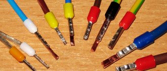
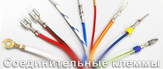
Using such cables, you can connect two or more wires to one point without using external electrical connectors. For this purpose, cable end sleeves (pin lug) are used and today’s article will be about them. An important advantage of this solution is that the switch has a very good contact surface with the cable or wires.
In addition, the terminals of such a sleeve can be used wherever it is necessary to connect cables such as a network line. Connecting a cable to an electrical connector of a product (module) without a clamped bushing may result in the connector screw pressing only on part of the cable wires, which will weaken reliability and conductivity.
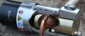
Crimping with screw and vice
If you do not have soldering accessories, and you consider point crimping using a center punch not reliable enough, then the third method remains.
Place this screw along the tip. Then you squeeze the entire structure in a vice. The end result should be approximately this form of pressing.
If one screw is not enough, a second one is placed on top of the depressed one and compressed again. You can initially use 2 screws, only installed on different sides of the sleeve. The main thing is not to overdo it and not break the sleeve.
To prevent the screw from moving, you can fix it with electrical tape.
In general, to summarize, we can say that these three methods have the right to life, and many people connect the power cable wires and lugs this way.
However, only a specialized factory tool can create a reliable and durable contact, which you will forget about immediately after crimping and it will not bother you during the entire period of work.
How to crimp wire lugs without tools
From the point of view of construction technology, crimping wires without the appropriate tool is prohibited, the only exception being rough installation to check the work performed. However, for any household work with low-current consumers, work without a crimping tool is allowed.
There are several methods for ending cords without tools:
- soldering using refractory high-temperature solders;
- “non-standard” crimping using cores, hammers, and notching the tip
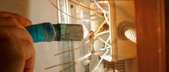
Soldering tip
For soldering, you, of course, do not need serious and expensive press pliers/crimpers, but the following “household” repair tools should be present in your arsenal:
- Soldering iron (from 80 W)/blowtorch/gas burner.
- Soldering kit (fluxes/rosin, various types of solders).
- Heat shrink tubing and/or electrical tape.
- Basic knowledge and skills of working with a soldering iron.
The algorithm of actions is as follows:
- if you have a soldering iron/blowtorch, heat it up to operating temperature, if you don’t have one, turn on the burner on the kitchen stove;
- While the tool is heating up, we perform operations to remove the insulation from our cord (remove with a margin of 0.3–0.5 cm), making sure not to damage the cores;
- we put the thermal insulating braid on the cord and move it to a safe distance until we need it;
- degrease the cleaned area;
- degrease the tip;
- apply flux to the inside of the tip;
- Pre-cut the solder into small pieces so that it covers the inside of the tip by about half to a third;
- apply flux with a soldering iron to the stripped part of the cord, tin it (if there is no soldering iron, then skip this step);
- carefully, holding the tip with pliers so that the solder particles do not fall out of it, place it on the kitchen tile (if you don’t have a soldering iron) or heat it with a soldering iron/lamp/burner for several minutes until the solder inside becomes plastic and liquid;
- as soon as the solder is ready, quickly and carefully take the cord by the insulation and install it into the tip, while continuing to heat the tip, holding it with pliers, if there is an empty space between the tip and the solder does not come out, then add solder to these places until it will not begin to “crawl out”;
- then turn off the soldering iron/burner and give it a few minutes for the solder to completely harden;
- After hardening, we wrap 2-3 layers of electrical tape around the connection between the cable and the tip, move the thermal braiding, securing it at the edges with electrical tape.
Crimping using a core/hammer
This method has many disadvantages, the main one being insufficient pressure, which can lead to heating of such a connection. However, it is often practiced, especially in cases where the connection will not work with high-current devices.
This method requires a minimum of tools:
- Hammer.
- Kern (optional, but recommended).
- A small file for metal.
- Vise (optional, but recommended).
- Conductive paste (highly desirable).
- Insulation tape and/or heat shrink.
To finish with these tools, we do this:
- remove the insulation from the cord (margin 0.3–0.5 cm);
- make sure that the wires are not damaged;
- straighten all the wire strands, twist them slightly (half a turn, no more!);
- take the tip and make a small cut with a file (about 1/5 of the entire length of the tip) on the wire side;
- put on the heat shrink, move it 10–20 centimeters so that it does not interfere; degrease the cord;
- evenly apply conductive paste;
- we clamp the tip in a vice or place it so that it can be comfortably held with one hand;
- after which we completely install the wire into the tip;
- we take a core and a hammer and begin to strike the central part of the tip, which should be “compressed” (if there is no core, then you can use the thin part of the hammer);
- make 4–5 fixation points;
- turn the tip over and repeat the operation;
- check the connection for strength;
- We put heat shrink on the connection, heat it;
- ready, the connection is pressed!
Heat shrink insulation of wires
Heat shrink tubing is made of a polymer material that shrinks when exposed to high temperature. After shrinking, such a tube tightly fits the insulated conductor, forming a reliable coating.
Heat-shrink tubing
Advantages of heat shrinking in comparison with other methods for insulating wires:
- ease of installation;
- eliminating the possibility of displacement of the insulating layer;
- providing additional mechanical strength as well as protection for the conductor;
- long service life;
- tightness of the coating.
Heat shrink tubing sizes
The main parameter for the size of heat shrink for wires is the internal diameter of the tube before shrinking. Sometimes the marking of heat-shrinkable tubes involves the designation through a fraction of the diameter after shrinkage or the coefficient by which this diameter is determined.
Important! The most common shrinkage ratio is 2:1, meaning that after exposure to temperature, the heat shrink tube will shrink by 2 times. However, there are also heat-shrinkable tubes with a shrinkage ratio of up to 6:1.
Heat-shrinkable tubes for wires made in Europe are produced in standard diameters in terms of the metric system (in the original, diameters are measured in inches) 1.6 mm, 2.4 mm, 3.2 mm, 4.8 mm, 6.4 mm, etc. .
Russian and Asian manufacturers produce products with diameter pitches of 0.5 mm and 1 mm.
Based on the wall thickness after shrinkage, thin-walled and thick-walled tubes are distinguished.
The thickness of the walls of the first after exposure to high temperature is no more than 1 mm. Typically, the shrinkage ratio of such tubes ranges from 2:1 to 4:1. They do not have an adhesive layer that ensures increased tightness of the insulation.
Thick-walled heat-shrinkable tubes have a post-shrink wall thickness from 1.5 mm to 4.5 mm, their shrinkage ratio can reach 6:1, and the inner layer is usually adhesive.
Heat-shrinkable tubes are sold in 1 m sections or in coils with a winding length divisible by 25 m.
How to work with heat shrink
In order to insulate a conductor using the heat shrink method, no special skills or equipment are required. Basically, all you need is a sharp knife or scissors, and a heat source, such as a regular lighter. The diameter of the heat-shrinkable tube is selected in such a way that a conductor can be freely threaded into the tube before shrinking. The diameter after shrinkage should be less than the cross-sectional diameter of the conductor.
Algorithm for insulating wires with heat shrink.
- We cut off a piece of tube of the length necessary to cover the exposed part of the conductor, taking into account the longitudinal shrinkage coefficient, which is usually 5-10%. The cuts should not have nicks or irregularities - this may negatively affect the quality of the insulating layer.
- A piece of tubing is placed over the wire before the connection it will insulate is made.
- After installing the connection, a piece of heat-shrinkable tubing is placed in the intended place.
- The insulation is heated extremely evenly from the middle of the tube to its edges (in small sections, heating is possible from one edge to the other), this will avoid excessive longitudinal shrinkage, and will also protect against the formation of air bubbles under the insulation layer.
Heat shrink
Clamping wires of different sections into a common terminal
The most difficult task during installation (especially for novice craftsmen) is combining conductors of different cross-sections in one connector. To avoid problems, you should adhere to the following rules:
- Wires of larger and smaller cross-sections are diverted from each other. This can be done thanks to different insulation of the conductors, as well as a reserve in diameter at the tip skirt. The thinner product is stripped a greater distance, after which it is moved forward so that it ends up in the end first.
- At the second stage, the main wire is inserted into the tip all the way and crimping is performed.
A similar principle should be followed in the case of double NSHVIs - first the thin conductor is inserted, and then the main wires are inserted. For crimping, it is recommended to use STK-03 pliers. While working, make sure that the tool does not snap into place. To do this, hold the ratchet lever while crimping.
Termination technology
Terminating a wire or cable yourself with a special tool will not present any difficulties. You just need to take a suitable tip, push it onto the core as far as it will go and press it with a press. In this case, the number of crimping points depends on the design of the crimping tool. If crimping is performed using a matrix with point contact, press the tips in 2 or more places distributed along the length. If the part of the tip being crimped is comparable to the width of the indentation after crimping, then one point is enough. The sleeves are crimped with at least two indentations, one on each side to hold each of the conductors. In general, the number of crimping points depends on the width of the “jaws” of the crimping tool matrix.
This is necessary for better contact, minimal contact resistance and mechanical strength. In simple words, in this case the conductor will not jump out of the tip or sleeve.
Pay attention to the recommendations given in the instructions or appendix to the crimper (crimp, press tongs) regarding working with tips of different diameters or cross-sections.
The rules and technology for terminating and crimping cores are described in the following documents:
- VSN 139-80
- I1.09-10
In addition, an important requirement should be noted: to crimp an aluminum conductor, you must additionally use quartz-vaseline lubricant, which prevents the formation of an oxide film that impairs contact
You can also do without the so-called pliers - manually flatten the sleeve with a hammer or pliers, but in this case there is no guarantee of good contact, so it is better to spend at least on a stripper for reliable termination of the cores, or even better, a crimper (special crimp). We talked about how to use the stripper in a separate article.
Please note that if you decide to terminate a single-core conductor using pliers, you must select the correct crimping die. If selected incorrectly, there is a high probability of damaging the sleeve or tip by simply tearing its metal
In addition, there are special tips for soldering. In this case, the termination of wire or power cable cores occurs in two stages:
- The core, stripped to a metallic shine and treated with neutral solder, is inserted into the tip until it stops.
- Solder is poured through a special hole.
Video instructions for using the press
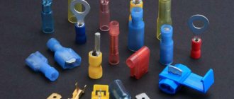
Types of tips
You can quickly terminate a cable or wire using special lugs. Their range is varied - there are lugs for aluminum and copper wiring, for single-wire and multi-wire conductors. Each product has its own marking according to GOST, by which you can understand the purpose and characteristics of the electrical device, as well as climatic operating conditions.
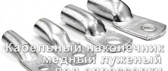
Ferrules for copper wires TTM and TML
TML cable lug
Stranded copper strands can be terminated with special lugs made from a copper pipe drilled for a bolt. There are two modifications of such devices - uncoated and tinned. They are also marked as TM (TML), after which the cross-section of the wire under the clamp is set in millimeters and the diameter of the tip hole in mm. Fastening of such clamps is carried out by crimping using special pliers. It is not recommended to use ordinary pliers or a hammer, otherwise you may damage the mechanism. The number of crimps must be two or more for reliable installation.
Such lugs can also be used for single-wire conductors
It is only important to choose the right size, as otherwise the core may break off. Before installation, the ends are cleaned of the insulating layer and oxide to a characteristic metallic sheen.
The scope of application of such products is quite wide. They can be found in connecting cable risers at the distribution input device in the entrance, in grounding metal distribution boxes, connecting electric stoves, and branches. They are also actively used in industry.
Wires and cords with a cross-section from 2.5 sq. mm to 240 sq. mm are suitable for termination.
TML(o)
TML(o)
A less commonly used modification of TML lugs is a device for crimping with a control window that allows the technician to see the process of installing the conductor in place.
Such products are also mounted by soldering. Application area: industry. They are practically not used in everyday life, so many home electricians and housing and communal services specialists have no idea about the existence of such devices.
THERE
TA tip
TAM aluminum and copper cable lugs are used to connect aluminum wiring to copper busbars on input and distribution devices. The product is a tip made of two metals, in which the shank is made of aluminum, and the body itself is made of copper. There is no transition resistance due to frictional diffusion. Installation method: crimping.
TA
Used for aluminum wires. Externally similar to TM brand products, but made of a different material. They have a minimum size of 16 sq. mm.
Connecting and terminating conductors of aluminum wires and cables can only be done using quartz-vaseline lubricant, which prevents the formation of oxide on the surface. Thanks to it, contact with air is reduced.
Other types of tips
PM tip
Copper wires in household appliances are often terminated with copper lugs for soldering. The devices have special “ears” that allow you to securely fix the conductor. Such products include the PM brand, in which the “ears” are combined in a production design. Used for wires with a cross-section of 2.5 sq. mm.
Reducing the dimensions of switching devices and protective equipment has led to a change in the size of the clamps. For this reason, NShP pin wire terminations are increasingly being used.
NB cable bolt and mechanical lugs are actively used in industry. With their help, power cables with a cross-section from 25 sq. mm to 240 sq. mm are terminated. They are made of aluminum alloy and have good corrosion resistance. To create a tight seal, a heat-shrink tube is included.
The range of tips is very diverse; you can always find a device for this type of conductor, but many people use homemade ones
Such products have an important advantage - the ability to create a tip to any size. They can be produced quite simply - you need a tube of the desired material, flattened at one end, and then a hole is drilled in it
Homemade devices are used in grounding devices.
https://youtube.com/watch?v=geLA-dSlunM
Working methods
When using NShVI tips, it is worth considering the following:
"SKIRT" COLOR. The product shows the cross-section of the connector. As a rule, we use the KVT standard, which is characterized by the following:
- Black - 1.5 sq. mm;
- Blue - 2.5 sq. mm;
- Gray - 4 sq. mm;
- Yellow - 6 sq. mm;
- Red - 10 sq. mm.
It is worth noting that goods from stores deviate from the standard. At the same time, the size of the product and color do not correspond to KVT in any way. The downside is low quality and rapid destruction
That’s why when choosing, you should pay attention to the color of the “skirt” and its correspondence to the cross-section
PACKAGE. As a rule, NShVIs for crimping come in packs of one hundred products, which are packed in groups of five in a larger package. It is not possible to purchase such a product individually.
If you need to connect two cables, there is no need to “reinvent the wheel.” NShVI-2 connectors of the same type of installation are available for sale. For example, if you buy a product for four square meters. mm, it easily accepts two wires per 4 sq. mm.
How to choose the right terminals for wires
When choosing the most suitable cable lug, you need to be guided by the fact that the electrical conductor and sleeve correspond to the specified automatic parameters. This principle is relevant for any fixation, since when using a shank with a large diameter, there is free space that impairs contact.
There is no need to fill and crimp it with debris using wire or solder, as this may solve the problem. The plate is selected according to the diameter of the hole and the cross-section of the bolt or terminal. They are also chosen based on the quality of the core. If the crimped terminal and dielectric have a bare area, it may cause oxidation, fracture and fire.
Correspondence of diameter to bolt cross-section
Classification of tips for crimping
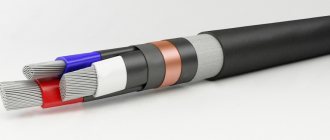
To connect electrical cables, lugs and sleeves are used, which are available for single-core or multi-core cords. Products are made from cold-rolled rods, pipes, and sheets. The sleeves should be selected in accordance with the diameter of the core being connected.
According to the material of manufacture, the types of tips are:
- copper;
- aluminum;
- mixed (copper-aluminium).
There are also tinned copper ends, whose feature is its ability to resist oxidation.
In addition to the material, sleeves can be classified according to their main functions:
- for connection;
- for connection.
To connect
There are several types of lugs for wires connected to terminals. Their distinctive feature is the ability to temporarily connect or frequently change from one terminal to another:
- ring (characterized by reliability);
- hooks (allow connection without removing the screw);
- fork (convenient for reconnections);
- pins (for clamping);
- round needles (minus – small contact surface);
- sleeve type (used in all types of terminals);
- for cable (have a hole for a screw);
- with a bend.
For connection
The product is a hollow tube made of a certain material into which the corresponding cores are placed.
There are two types of connection products:
- inside which the wires are connected;
- which connect already terminated cords.
Labeling: how is it useful?
Each tip is marked with an alphanumeric code - this is a marking. It can provide basic information for selecting the correct electrical installation component. It looks like this: TML 70-10-11.5. Each symbol carries information:
- T is a pipe, a semi-finished product for making a part;
- M – material, in this case copper;
- L – processing method, means that this element is made of tinned copper;
- 70 (first digit of the code) – section in mm;
- 10 (second digit of the marking) – diameter of the mounting hole for the bolt in mm;
- 11.5 (third digit) is the internal diameter of the shank in mm into which the wire is inserted.
Common markings and their interpretation are presented in the table.
| Letter code | Image | Explanation and description |
| TML | Made from tinned copper, universal in use, protected from environmental influences | |
| TA | Made of aluminum, suitable for aluminum wires only | |
| THERE | Aluminum-copper for connecting aluminum wires with copper contacts | |
| SIP | Tube insulated, aluminum with copper terminal | |
| NSHVI | Sleeve pin, insulated, most applicable in everyday life |
The production of parts for electrical installation is regulated by GOST, but you can find products manufactured according to specifications or European standards; their markings will have a different appearance.
Connection of current-carrying conductors up to 10 mm/sq.
To organize branches and connections of aluminum and copper conductors, press jaws and standard sleeves are used. Connections in such cases can be one-sided, when the wire is inserted from one side of the sleeve, or two-sided. The material of the sleeves is selected in accordance with the material of the cores
Cable crimping algorithm:
1. At the ends of the cores, the insulation is removed by 2-3 centimeters. They must be cleaned to a metallic shine. If the conductors are aluminum, then they must first be lubricated with quartz vaseline paste. Copper wires, in turn, can be left clean.
2. In accordance with the technical table, punches, dies and sleeves are selected. If the sleeves are too large, then the free space can be sealed using additional cores. When using stranded conductors, removing the conductor wire to adjust the cross-section is not allowed.
3. The cores must not be twisted. They are laid parallel to each other, after which the connecting sleeve is put on. If copper wires are used, then before putting on the sleeve, they must be wrapped in two layers of copper or brass foil. The thickness of the foil is 0.2 millimeters and the width is 20-22 millimeters.
4. The connections are crimped using press pliers using the local indentation method. The degree of crimping is determined by the technical table.
5.After crimping, the connections are wiped with a rag soaked in gasoline and insulated.
Why crimping?
Soldering a stranded wire is not the easiest operation, because you need to expose all the wires, make sure that they are clean in terms of contact, and only then start soldering. Any core in a stranded wire has insulation, and this often creates difficulties in establishing reliable contact.
Just crimping the cable lugs solves all these problems, because with the help of mechanical force (compression) not only the insulation of individual cores is destroyed, but also a strong connection of the entire cable is created for better contact.
This is where the moment arises of how to choose the correct sleeves for crimping wires, because they are made from different materials and have very precisely specified current characteristics.
The problem is that the size of these cartridges is small, and the markings are unclear to those who are not specialists. But before that, let's define the difference between a sleeve and a cable crimp lug.
Another point that is not even in the markings is the moment of tightening the sleeve or tip during crimping. And they are completely different for different types of tips, such as:
- ring (NKI).
- fork (NVI).
- pin round (NSHKI).
- flat (plug) connectors (RPI-P, RPI-M, RSHI-P, RSHI-M, etc.).
- piercing type couplers (OV).
Here it is necessary to return to the tool that is used to crimp the wires, because on each tool the dimensions are indicated for the standard shape of the jaws, and the force itself is accurately measured by diameters. So, unless you made a mistake with the diameter, you cannot apply excessive force.
And, despite the fact that the lugs for wires for crimping are different, with the same diameter both the force and the standard of the tool will be the same. It's a pity that this parameter is not reflected on the labeling. Apparently because such work is usually done by professionals, not home electricians.
But it is precisely the standards that allow home electricians to stock up on universal crimping pliers and crimp cable lugs for their own purposes without any problems. This procedure is quite simple to master, and technologically it is the same for crimping an RG-45 connector and a tip for a three-phase machine.
When crimping a multi-core cable, you cannot do without special lubricants. Therefore, use sleeves and tips that already have this lubricant inside. In any case, this is a one-time operation. It is not possible to remove a part to move it to another location.
As a result, having mastered the installation of sleeves and tips, you will be able to quickly restore the desired connection, carry out repairs without problems, as well as a connection that, in fact, will not need repair for many years.
What is crimping wires with sleeves?
Crimping with sleeves - permanent connection of wires
Crimping is a common procedure in electrical engineering; its peculiarity lies in the connection of electrical wiring with special sleeves. The connecting mechanism is a connecting tube made of metal. To crimp the wires, their cores are inserted into a sleeve. By crimping the tube with the wires inside, it is possible to achieve a reliable connection. At home, crimping is done using pliers, but it is preferable to use a special tool - press pliers.
The sleeve is compressed in two or three places, and the pressed area is insulated using insulating PVC tape or heat shrink tubing. Sometimes insulated connecting sleeves are used to connect elements; in this case, there is no need to re-process the electrical wiring section.
Connecting wires with sleeves must be carried out in the following cases:
- It is necessary to connect wires with a large cross-sectional area.
- There is no possibility of using alternative methods of connecting the wire. For example, wiring inside a distribution box where visibility is poor at high altitudes or where it is impossible to place the terminal block.
- It is necessary to connect wires in lines with high load.
Crimping sleeves for wires have their advantages and disadvantages. The first ones predominate:
The crimping tool is equipped with a comfortable working area. This principle of operation allows you to perform assigned tasks in a limited space, for example, in distribution boxes or a socket box. Inside the socket box, crimping the wiring contacts allows you to shorten the wires to an absolute minimum. To compress the tube used, crimping pliers are used. Unlike analogues, this tool does not require a connection to electricity to operate and belongs to the group of manual ones. If the power is not yet connected, crimping is the only reliable way to connect the wires. To carry out soldering or welding, you must have certain knowledge and skills. Any person can cope with crimping after the first trial time
It is important to have press pliers and consumables; in extreme cases, you must have pliers.
The disadvantages include the following:
- The need to constantly have in stock and regularly replenish stocks of cartridges of different sizes.
- The connection is characterized by considerable dimensions, which sometimes complicates the implementation of certain tasks.
It is also worth mentioning the significant costs of consumables.
Common Mistakes
For crimp connections, select a sleeve of the appropriate size. If the diameter of the core is larger, then it has to be sharpened. Its thinning leads to an increase in the resistance of the contact area. In this place the wire will heat up and may burn out over time. Mechanical strength is also lost. External influence on the connection can lead to rupture.
An increase in diameter, compared to a wire, similarly leads to a deterioration in contact. The presence of gaps between the cores reduces the reliability and strength of the connection. In order to save money, dividing the sleeve into several parts makes installation inconvenient and reduces the contact length. You should also not use improvised tools when crimping. Pliers, a hammer or a chisel will not bring the desired effect, but can cause irreparable damage.
Connecting wires using crimping will not be a problem. If the sections are consistent, the work is carried out carefully and safety precautions are followed, you can get an excellent result.
Which tip to choose
Before you begin crimping, you must select the correct tip. It is worth remembering that tips come in different types - different sleeve thicknesses, different inlet diameters. Moreover, this happens with tips of the same section.
Therefore, it is not always the same matrix; you can crimp 2 different lugs for a wire of the same cross-section. In addition, the number of sleeve crimps may also differ. If you want to achieve a high-quality connection that will reliably serve you for years, use the following recommendations.
Backlash may be acceptable, but it should be minimal. If the tip material is aluminum, then the choice is simpler. Select a tip of the same cross-section as the cross-section of the wire. You can navigate by the inscriptions on the blade of the contact part.
But if the material of the product is copper, then certain difficulties arise. But there are several solutions here too.
- There are GOST tables that can be used to select the desired type. But this is not entirely convenient, because... you need to clearly know and distinguish between core flexibility classes, and you won’t have these tables at hand.
- measure the diameter of the core with an ordinary caliper. Then compare it with the diameter of the inner part of the tip shank. This can be done with the same caliper, or using the inscriptions on the blade.
The third number in the abbreviation TM-35-8-9 will be exactly the required diameter. That is, if the diameter of the core that you measured turned out to be 8.5 mm, then the most suitable tip would be the one marked TM-35-8-9.
Please note that the diameter of the core should be slightly smaller, but not larger than the diameter of the shank.
The material of manufacture of the tip and sleeves must be the same as the material of manufacture of the wire or cable core. Connect aluminum wires using aluminum sleeves and lugs. Copper with copper. Otherwise, corrosion processes cannot be avoided.
If you need to connect an aluminum lug to a copper contact (on a switch or switch), use an aluminum-copper lug or use aluminum-copper washers.
There are special aluminum-copper sleeves for joining copper and aluminum cable cores.
Rules for working with insulated tips
- Only stranded wires can be crimped with insulated lugs. Mono-core ones should be used for their type of non-insulated lugs.
Right angle - how to calculate using available tools
When choosing, be sure to pay attention not only to the diameter and cross-section, but also to the shape of the contact blade. Do not use fork lugs on moving or vibration-prone contacts!
- the insulation from the core is removed exactly to the length of the compressed tube into which the core is inserted. Unlike bushings, it will be extremely inconvenient to bite off the excess with a cable cutter.
- When pressing, insert the tip into the press matrix so that the seam of the shank is on top and strictly according to class=”aligncenter” width=”372″ height=”193″
- follow the color markings on the matrices with the colors of the tips themselves
- When pressing insulated tips with pliers, make sure that each circuit of the matrix is crimping its part of the core and insulation, and also insert the tip into the matrix only from the marked side
- If the dies are not completely closed at the end of clamping the handles, then you have not selected the correct tip size. If the insulating sleeve is damaged, the tip must be replaced.
Common types of tips
In electrical installation practice there are dozens of types of connectors. This diversity is due to the wide list of wires used. Each type of cable has its own tip. It must match the material and cross-section of the current-carrying conductor.
Copper tips TM
Manufactured from seamless tube. This is indicated by the letter - T. The tube is made of copper - M. The full marking looks like this: TM 35-10-9. Here:
- T - tube;
- M - copper;
- 35 - cross-section of the cable for which this tip is intended, sq. mm;
- 10 — diameter (grade) of the fastening screw, mm;
- 9 is the diameter of the shank, that is, the hole into which the cable core is inserted.
If dimensions allow, the tip model is indicated on its surface. If it is too small, then the nominal cross-section of the connected cable is stamped on the product body. For example, the number “4” next to the mounting hole means that a conductor with a cross-section of 4 square meters should be inserted into the tip. mm.
Copper with tinning TML
Copper is a good conductor of electric current. However, a greenish coating is often found on TM tips. This is a layer of copper oxide, which is no good for reliable current transmission. To combat this phenomenon, the tips are additionally coated with a protective anti-corrosion tin coating. The resulting product here means tinning. Otherwise, the TM and TML markings are similar.
Tinned wire lugs
The protective layer prevents oxidation of the copper tip. Therefore, it can be used in more humid areas. Due to increased reliability, TML is suitable for connecting critical electricity consumers.
Tinned copper with control window TML (o)
Before installing the current-carrying conductor into the tip, the protective insulation layer is removed from it. There are a couple of subtleties:
- The stripped core should completely enter the tube and rest against its end. There should be no void left in the tip cavity.
- The cable must be stripped to a minimum length. So that there is no exposed section of wire without insulation left at the tip shank.
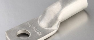
Aluminum TA tips
This type of connector is made of aluminum tube. This is indicated by the letter "A". TA lugs are designed for branching aluminum wires from busbars of similar material.
TAs have a long service life. Aluminum has increased resistance to moisture from the air and is practically not destroyed by it. This material is several times cheaper than copper, so sometimes people choose aluminum fasteners.
Aluminum cable lugs
TA are produced for wires with a cross-section of 16 square meters. mm and above. They also require the use of quartz-vaseline lubricant for additional surface protection.
Copper-aluminum TAM
The structure of these connectors uses two metals: copper and aluminum. They are connected to each other through frictional diffusion. One metal penetrates another at the molecular level. Therefore, high contact resistance is avoided.
Other types of tips
The types of fasteners listed are not sufficient to perform all electrical tasks. Therefore, in practice, other types of tips are often found:
- PM - cable lugs for soldering. They are made from sheet copper grade M1. In addition to soldering, this type of tip is also suitable for crimping. Available for cables with cross-sections from 2.5 to 240 sq. mm.
- NShP - pin flat. Used to connect copper cables. Made of copper. The main purpose is to connect wiring to circuit breakers. Inside it has ring notches to improve contact with the current-carrying conductor.
- NShV - pin bushing. Common in modern equipment. Made of electrical copper with a protective coating. Used to connect multi-core copper wires with a cross-section from 0.25 to 150 square meters. mm.
- NSHVI - insulated pin bushing. Equipped with an additional insulating plastic skirt.
Features of using NShVI tips
Wire lugs for crimping: types, nuances of operation
Electrolytic copper is used for the manufacture of pin sleeve lugs. There is insulation on the back of the product. To prevent corrosion from damaging the metal, copper is treated using galvanic tinning. The size of these tips varies between 0.25-150 mm.
When crimping NShVI, time is significantly saved, which simplifies the process of connecting electrical devices. The tips are suitable for household use. They are designed for crimping multi-core wires of any type. Manufacturers produce two types of NShVI. Some lugs are used for crimping one wire, while others are designed for two.
Products are marked as follows:
- Single - the first digit of the marking indicates the section size, and the second displays the length of the contact part.
- Double - the number “2” in brackets indicates that this tip is intended for splicing two wires, and the next number means what the cross-sectional size of each of them is.
The sizes of NSHVI crimp lugs range from 0.25 to 150 mm
It is desirable that the size of the shank in the tip be slightly larger than the cross-section of the wire, i.e., its bare wires. So, for a 1.25 mm cable, you should purchase an NShVI with a cross section of 1.5 mm.
Basic rules for crimping wires with sleeve-type lugs
You can connect wires efficiently using a lug at home, without professional skills and knowledge. To do this you need to adhere to the basic rules:
- Select the correct type and size of wire lug for crimping.
- Clean the conductors thoroughly and correctly.
- Use only specialized tools for work.
- Follow the crimping technology exactly.
Typically, the insulation on the wire is removed taking into account the size of the contact part of the tip. After stripping, the end of the core should coincide with the edge of the sleeve. To achieve this, you need to add 2-3 mm to the length of the cleaned area
It is very important to choose the correct tip size. In order not to make a mistake, you need to be guided by the color markings in which the insulating cuffs are painted. For crimping wires with ferrules, you must use only special tools. For crimping wires with ferrules, you must use only special tools.
For crimping wires with ferrules, you must use only special tools. For crimping wires with ferrules, you must use only special tools.
There are some subtleties when working with insulated connectors. It is imperative to ensure that the insulating material on the wire goes all the way inside the cuff and is completely covered by it.
Preparatory work is carried out in the following order:
- The veins are cut strictly perpendicularly.
- To remove the insulating layer from the cores, it is necessary to take into account the size of the shank and the increase.
- If the conductors are copper, the oxide film must be removed from their surface. To do this, the exposed area is degreased and then lubricated with technical grade Vaseline.
- If the shape of the cores is sectoral, you will have to round them.
- If the wire cores are made of aluminum, this metal must be cleaned to a shine. After this, the bare area is treated with quartz-vaseline lubricant, which will prevent the appearance of an oxide film.
Basic mistakes when crimping connections
The main mistake when crimping is the wrong choice of sleeve. If it is significantly less, then the conductor will be strongly pressed by the edge of the sleeve. This may cause the flattened wire to break.
On the other hand, if it is too large, then the contact will not be very reliable. In such a situation, the wires may wobble inside the core. Over time, such connections will heat up and burn, which will ultimately lead to loss of contact.
The second mistake is incorrectly selected punches and dies. This can lead to a similar effect, resulting in over or under crimping of the sleeve. This problem is complicated by the fact that the working elements of the tool wear out over time and lose their primary characteristics.
IMPORTANT! Do not shorten the factory sleeve - this will reduce the reliability of the contact. The third mistake is using a chisel and hammer to crimp cable lugs and sleeves.
From the point of view of officially accepted methods, this is a terrible crime, but in life there are various situations and, in extreme cases, their use takes place. If it is possible to purchase good tools, then there should be no alternative.
The third mistake is using a chisel and hammer to crimp cable lugs and sleeves. From the point of view of officially accepted methods, this is a terrible crime, but in life there are various situations and, in extreme cases, their use takes place. If it is possible to purchase good tools, then there should be no alternative.
In the end, we present the recommended combination of cross-sections of cores and cable sleeves:
1. The total cross-section of the cores in the press sleeve is 7.5 mm/sq. Cable press sleeve – 4-1. Press jaws – PK-3.
2. The total cross-section of the cores in the press sleeve is 13 mm/sq. Cable press sleeve – 5-1. Press jaws – PK-3.
3. The total cross-section of the cores in the press sleeve is 15 mm/sq. Cable press sleeve – 4-2. Press jaws – PK-3.
4. The total cross-section of the cores in the press sleeve is 20 mm/sq. Cable press sleeve – 6-1. Press jaws – PK-3.
5. The total cross-section of the cores in the press sleeve is 26 mm/sq. Cable press sleeve – 5-2. Press jaws – PK-3.
6. The total cross-section of the cores in the press sleeve is 41 mm/sq. Cable press sleeve – 6-2. Press jaws – PK-3.
The use of sleeves with a cross-section smaller than the wire
Never use sleeves smaller than the required diameter. To insert wires into them, it is necessary to reduce the diameter of the core, which is done by cutting off part of the conductor and reducing the cross-section of the wire.
Those. if you want to extend a wire with a cross-section of 2.5 mm2, and your sleeve is 1.5 mm2, you do not need to take a file and trim the wires so that they fit into the sleeve.
Reducing the cross-section of the wire also leads to a decrease in the mechanical strength of the connection. With any external influence it can simply break. Finding a break in an extensive network is not an easy task even for a professional electrician, unless, of course, there are special instruments. But they are not in every home.
Using large diameter sleeves
Increasing the diameter of the sleeve also does not bring any benefit. It is not always possible to achieve a reliable and strong connection. The use of the “folk” method of bending the ends of the wire in half can be considered only a partial solution. Practice shows that the mechanical strength of the pressed joint in this case is also reduced by almost half.
Cutting cartridges into several pieces
Many beginners use this method to save on cartridges. Do not shorten the factory sleeve. This leads not only to the inconvenience of working with pliers, but also to an increase in resistance. The consequences are described in the first tip. Mechanical strength also decreases due to a decrease in the length of the contact section.
Clamping wires of different sections into a common terminal
The most difficult task during installation (especially for novice craftsmen) is combining conductors of different cross-sections in one connector. To avoid problems, you should adhere to the following rules:
- Wires of larger and smaller cross-sections are diverted from each other. This can be done thanks to different insulation of the conductors, as well as a reserve in diameter at the tip skirt. The thinner product is stripped a greater distance, after which it is moved forward so that it ends up in the end first.
- At the second stage, the main wire is inserted into the tip all the way and crimping is performed.
A similar principle should be followed in the case of double NSHVIs - first the thin conductor is inserted, and then the main wires are inserted. For crimping, it is recommended to use STK-03 pliers. While working, make sure that the tool does not snap into place. To do this, hold the ratchet lever while crimping.
Design nuances and characteristics
The NShVI tip, as a rule, has the following features:
- During the manufacturing process, M1 type copper is used;
- The upper voltage threshold is 690 V;
- The surface of the connector is subjected to electrolytic tinning;
- The dimensions of the connectors are designed to connect one cable (installation is carried out taking into account the cross-section);
- Insulation is performed using polypropylene, which does not contain halogens;
- The insulating element is characterized by high thermal resistance - it can withstand temperatures up to 105 degrees Celsius;
- KBT bushing connectors are manufactured in one color and have a common DIN standard. This is done in order to eliminate difficulties during the installation process. In addition, the color is selected taking into account the marking DIN 462228, part 4.
- The conductor is crimped on top of the copper bushing;
- The NShVI cuff has a conical shape, which eliminates problems in the process of inserting a stranded wire into the inner part of the sleeve.
Product characteristics are presented below.
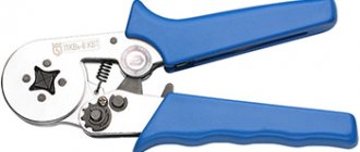
Required Tools
Crimping is carried out with a special tool that allows you to create the necessary force. The following tools are popular:
- Press pliers for crimping PK2 and PK2M lugs are used for terminating cores with a cross-section of up to 10 sq. mm;
- PK1 and PK1M brand tools are a more powerful version of hand pliers;
- hydraulic pliers allow you to crimp wires up to 10 sq. mm;
- In industrial production, a hand press is used. It is suitable for wires up to 240 sq. mm;
- hydraulic press with electric drive is used for cables up to 300 sq. mm.
Types of instruments
Press pliers with hinges increase the pressure of the tool, which makes the manual crimping process easier. Devices with a ratcheting mechanism are especially convenient. They prevent the instrument from unclenching until the procedure is completed.
You can watch how to crimp a wire without tools in this video:
Types of press jaws
The manual crimper is used for crimping non-insulated cable lugs, contact connectors, terminals and contact sleeves of various sizes. If a manual crimper has special blades (usually they are located where the handles are attached), then this tool can also be used for cutting cables and wires.
Electric pliers are a multifunctional tool for professional use. They can do almost any work with wires. Electric pliers are mainly used for cutting and stripping wires, but they can also be used to crimp uninsulated and insulated cable ends.
A crimper is a tool for crimping wire lugs, twisted pair cables, and connectors. It has two long handles (one or both can be movable) and a massive working part in the form of metal jaws, which have holes for cables.
When the handles are brought together, the jaws close and the cable connector is crimped using forceful pressing. Some models have a blade on the working part, which simplifies the work - no additional tools are required to cut the cable.
How to use
The lugs are used for stranded wires and crimping. Cable crimping is done using crimping pliers, hydraulic pliers and crimping pliers to crimp the terminals. There are three preparation steps before it. First, the depth of the shank is measured, a mark is made on the cable, and the conductors are cleared of the insulation layer. Next, degrease the wire and put on the tip. Then put the wire in the press pliers.
Note! Make the first crimp with a millimeter indent. The second one at the same interval
Then squeeze the handle until it makes contact. If the shank is long, continue to the colored skirt. You only need to insert several wires into one shank. Then crimp the product.
In general, cable lugs are devices to prevent wire contacts from becoming loose and resulting in excessive heating of the conductors. There are aluminum, copper, combined, brass and aluminum-copper; for crimping, tightening and soldering. Also sold in ring, horn, connector, plate, plug, pin and tubular models. Used in all electrical appliances. To select and use them correctly, you need to be guided by the diagram presented above.