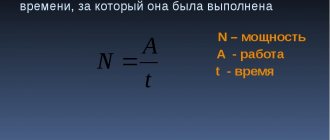
Good day to all. In the last article, I looked at the types of connections of energy receivers in electrical circuits, as well as Kirchhoff’s laws, which determine the basic relationships of currents and voltages in these circuits. But in addition to knowledge of the basic laws of electrical engineering, it is necessary to be able to calculate unknown parameters of electrical circuits based on given known parameters. So, for example, based on known voltages, EMF and resistances, it is necessary to know what power a particular energy receiver, as well as the entire circuit as a whole, will consume. This is what we will do in this article.
To assemble a radio-electronic device, you can pre-make a DIY KIT kit using the link.
Electrical circuits
An electrical circuit is a collection of devices through which electric current flows.
Let's consider the simplest electrical circuit. What does it consist of? It has a generator - a current source, a receiver (for example, a light bulb or an electric motor), and a transmission system (wires). For a circuit to become a circuit, and not a set of wires and batteries, its elements must be connected to each other by conductors. Current can only flow through a closed circuit. Let's give one more definition:
An electrical circuit is a current source, transmission lines and a receiver connected to each other.
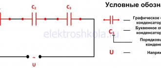
Of course, source, receiver and wires are the simplest option for a basic electrical circuit. In reality, different circuits include many more elements and auxiliary equipment: resistors, capacitors, switches, ammeters, voltmeters, switches, contact connections, transformers, etc.
Electrical circuit
By the way, read about what a transformer is in a separate article on our blog.
By what fundamental characteristic can all electric current circuits be divided? Same as current! direct circuits , and there are alternating current circuits . In a direct current circuit, it does not change its direction; the polarity of the source is constant. Alternating current changes periodically over time, both in direction and in magnitude.
Nowadays alternating current is used everywhere. Read about what Nikola Tesla did for this in our article.
Serial connection
For convenience, when depicting a branched electrical circuit, all resistances are drawn in the form of rectangles, which are resistors. Any such element can have two outputs. One is the beginning and the other is the end. Taking into account the above, we can formulate a definition for a serial connection of conductors: a connection in which the end of the previous element is connected to the beginning of the next one is called serial.
Any conductor has electrical resistance. The purpose of the conversion is to replace the alternating sequence with a single resistor. At the same time, in its electrical properties it should not differ from the entire chain. In simple words, this can be explained as follows: if you take two black boxes that have a pair of terminals each, and one will contain the entire electrical circuit, and the other will be its equivalent, then it will be impossible to determine which of them contains the circuit and which is the equivalent.
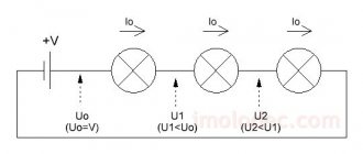
When connected in series, the following phenomena occur. Let there be a straight chain containing n resistors: R1 + R2 + … +Rn. Current strength is a quantity that is equal to the charge flowing per unit time. You can imagine that the electric current in the first resistor will be greater than in the second. As a result, a “traffic jam” will occur, and the speed of movement of the charges will slow down.
At the point of connection of the elements, electrons will accumulate, which will lead to an increase in voltage there. Accordingly, the current in the first resistor will decrease, and in the second, on the contrary, it will increase. This will lead to equalization of the number of charges passing through the resistors, so the current strength in almost an instant in the entire series circuit will become the same.
Voltage is the work done to transfer charge. According to the law of conservation of energy, its total value is equal to their sum at various stages. The total potential difference can be determined by adding the voltages across each element. This type of connection is described by the following expressions:
- I = I 1 = I 2 = ... = In;
- U = U1 + U2 + … +Un.
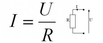
These equalities are fundamental to finding parameters when repeating resistors in a circuit. Using Ohm's law, you can find what the circuit resistance will be. The formula for finding it will look like this: Rpos = R 1 + R 2 +… + Rn.
Elements of electrical circuits
All elements of electrical circuits can be divided into active and passive. The active elements of the circuit are those elements that induce EMF. These include current sources, batteries, and electric motors. Passive elements – connecting wires and electrical receivers.
Receivers and current sources, from the point of view of circuit topology, are two-pole elements (double-terminal). To operate, they require two poles through which they transmit or receive electrical energy. Devices through which current flows from a source to a receiver are four-terminal. To transfer energy from one two-terminal network to another, they need at least 4 contacts, respectively for receiving and transmitting.
Resistors are elements of an electrical circuit that have resistance. In general, all elements of real circuits, down to the smallest connecting wire, have resistance. However, in most cases this can be neglected and the elements of the electrical circuit can be considered ideal when calculating.
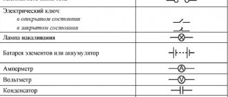
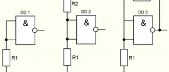
There are symbols for depicting circuit elements in diagrams.
By the way, read more about current strength, voltage, resistance and Ohm’s law for elements of an electrical circuit in a separate article.
Current-voltage characteristic is a fundamental characteristic of circuit elements. This is the dependence of the voltage at the terminals of the element on the current that passes through it. If the current-voltage characteristic is a straight line, then the element is said to be linear. A circuit consisting of linear elements is a linear electrical circuit. A nonlinear electrical circuit is a circuit in which the resistance of sections depends on the values and direction of the currents.
What are the ways to connect elements of an electrical circuit? No matter how complex the circuit is, the elements in it are connected either in series or in parallel.
When solving problems and analyzing circuits, the following concepts are used:
- A branch is a section of a circuit along which the same current flows;
- Knot – connection of chain branches;
- A circuit is a sequence of branches that forms a closed path. In this case, one of the nodes is both the beginning and the end of the path, and the other nodes appear in the circuit only once.
To understand which is which, let's look at the picture:
By the way! For our readers there is now a 10% discount on any type of work
The general scheme for calculating the planned level of cost of oil and gas production is as follows [p.54]
In Table. 2.14 shows a scheme for calculating the rating score for an enterprise. [p.66]
An example is the electrical industry [5]. However, in many industries, including oil refining, the integral indicator of the quality level has not yet taken its rightful place among the methodological tools of quality management. The main reason is cognitive. It is associated with the difficulties of synthesizing an indicator of the integral utility of a product from its particular dependencies on individual properties. The principle scheme for calculating the integral indicator of the quality level was defined more than 30 years ago [1]. It is established by formula (4.7). [p.88]
In table 91 shows a diagram for calculating planned and actual profits in UBR. The absolute amount of profit in a drilling organization depends mainly on the volume of drilling work and the level of its cost compared to the plan. [p.177]
The scheme for calculating payment for production assets for an oil production association is given in Table. 109. [p.205]
When forming specific capital investments according to the reproduction structure, the following calculation scheme is used. For oil-producing areas with an increase in oil production, capital investments are distributed in proportion to the volume of new oil production capacity, ensuring an increase in production in the area and replenishing its decline in the old well stock. Capital investments in the departments and organizations of the Ministry of Petroleum Industry and the Ministry of Geology of the USSR are distributed in proportion to the volume of new capacity aimed at increasing and maintaining existing capacities in the industry as a whole. [p.131]
When choosing the level of aggregation of fixed assets, the determining factor is the nature of the upcoming calculations and the possibility of their information support. In this regard, the calculation scheme, where the subject of planning is individual production units (LC, KS, etc.), seems to be the most acceptable. This is mainly due to aggregated calculations of indicators for the commissioning of fixed assets for gas transportation in the medium term. The purpose of such calculations is to prepare the necessary material for making fundamental decisions at the pre-planning and pre-project stages (as part of the development of the main directions for the development of the sub-industry). [p.36]
Here is the simplest scheme for calculating an oil production plan. It should be borne in mind that in commercial practice this work is more complicated. In particular, when calculating a plan for oil production from new wells, it is usually planned to drill a well-point in several areas with different efficiency indicators. [p.149]
In this program, the model is implemented in a form close to the mathematical model described in the last paragraph. The sign means multiplication, and the symbol symbolizes exponentiation. First of all, the fact that the operators stand in an arbitrary order, and not in the way they should stand based on the calculation flowchart, is striking. This is a great advantage of the dynamo language: when translating a program into the internal language of the machine, the rearrangement of operators in the required order is performed automatically. This is very convenient, as it allows you to change one relationship to another and introduce new variables without much effort on the part of the researcher. [p.264]
There is another problem associated with absorbing fixed costs. It consists in the occurrence of abnormal values of reported profit in relation to the volume of production and sales of products. Let us briefly illustrate this. Marginal costing eliminates the problems of treating the behavior of fixed costs as variables, since only variables are assigned to costing units, while all fixed costs are written off as expenses of the reporting period. Below is a diagram for calculating the cost per unit of production using two calculation methods [p.203]
The scheme for calculating the expected value (EV) can be expressed by a mathematical formula [p.400]
SETTLEMENT SCHEME FOR DOCUMENTARY LETTER OF CREDIT [p.219]
SETTLEMENT SCHEME FOR DOCUMENTARY COLLECTION [p.223]
It seems that the payment scheme through valuable packages has several advantages compared to the proposed non-cash payment schemes. It is convenient for making payments among participants in exchange chains and guarantees confidentiality. [p.215]
| Rice. 19.1. Scheme of settlements by payment orders for advance payment of inventory items |
| Rice. 19.2. Scheme of settlements by checks when paying for inventory items with preliminary deposit of funds |
| Rice. 19.4. Scheme of settlements by payment requests-orders for subsequent payment of inventory items |
By using the aggregate form of the index and following the established computational procedure, it is possible to solve the classical analytical problem of determining the influence of the quantity factor and the price factor on the volume of produced or sold products.
The calculation scheme in this case will be as follows [p.53] The scheme of settlements by payment orders is shown in Fig. 17.2. The payment order is valid for 10 days, starting from the day following the day of issue. In some cases, irrevocable orders are used that are valid for an indefinite period. [p.429]
| Rice. 17.2. Scheme of settlements by payment orders |
Cassock. 17.3. Payment scheme using a covered letter of credit [p.433]
| Rice. 17.4. Payment scheme using a guaranteed letter of credit |
The general scheme of settlements with deposited checks is shown in Fig. 17.5. [p.436]
| Rice. 17.5. Scheme of settlements using a deposited check book |
| Rice. 17.6. Scheme of settlements using payment requests-orders subject to acceptance by the payer |
| Rice. 17.7. Scheme of settlements using direct payment requests or collection orders |
The general scheme of settlements using collection orders and payment requests without acceptance is shown in Fig.
17.7. [p.442] The scheme of settlements by payment orders is shown in Fig. 7.2. [p.209]
| Rice. 7.2. Scheme of payment orders |
| Rice. 7.7. Scheme of settlements using direct payment |
Settlements by payment orders are a widespread form of settlements for commodity and non-commodity transactions. As a rule, they issue advance payment for goods and services. In this case, a payment order is drawn up for the amount of the preliminary payment, and after the terms of the agreement are fulfilled, the balance of the transaction amount is paid. The permissible amount of advance payment should not exceed 50% of the contract amount, in this case parity of the parties is maintained. When the supplier demands to pay 100% of the amount in the form of an advance, the rights of the buyer are violated, who withdraws funds from his turnover and essentially credits the supplier. This form of payment is advisable only if significant discounts are provided to the buyer. The scheme of settlements by payment orders is shown in Fig. 14.1. [p.341]
| Rice. 14.1. Scheme of settlements by payment orders. |
The profitability of an individual enterprise is largely subject to external influences.
In conditions of superinflation, it seems advisable to impose less stringent requirements on some enterprises (this should especially apply to enterprises in the manufacturing sector). In table Figure 2.15 shows a diagram for calculating a synthetic indicator based on the Altman formula. [p.70] Various schemes for calculating depreciation for the conditions of NGDU Ufaneft have shown that the most advantageous is the degressive-uniform method. [p.15]
Based on it, a calculation block diagram is built, shown in Fig. 36. In this flowchart, the same operations are carried out as in the mathematical model in the last paragraph, only they are arranged in an ordered form. T denotes the number of years in the time period that is studied in the simulation experiment. The designation NO is used instead of N0. Let us draw the reader's attention to the fact that when calculating the value of A, the function b (A, V) is used, which has not yet been described in the block diagram. Thus, it is necessary to separately construct a block diagram for counting function 6 (A,V). If this dependence is specified graphically, then constructing the function ft (A,V) using the ALGOL language is a rather labor-intensive (although not very difficult) task. We will not deal with this issue, but will immediately move on to the program for simulation calculations, implemented in the Algol language. This program uses the delta (A, V) function procedure; we will not provide the text of this procedure. The program looks like this: [p.259]
| Rice. 19.3. Scheme of settlements through letters of credit with preliminary otiiiame of commodity and material values |
In a market economy, great importance is attached to comparisons of profit with income-generating factors and the bases for its formation.
International practice has developed different schemes for calculating profitability (profitability)1. [p.73] Payment requests-orders represent the supplier’s requirement to the buyer to pay the cost of goods and services on the basis of attached documents (invoices, waybills, waybills, etc.). An indispensable condition for this form of payment is the payer’s consent to debit funds from his account. Such consent is called acceptance. The acceptance is signed by the manager and chief accountant and sealed. Refusal to accept a payment request-order is declared within three working days, not counting the day it was received by the payer’s bank. The refusal must be justified and confirmed by reference to the terms of the contract. Only claims permitted by law can be written off without acceptance. The scheme of settlements with payment requests and orders is shown in Fig. 14.2. [p.342]
Classification of electrical circuits
According to their purpose, electrical circuits are:
- Power electrical circuits;
- Electrical control circuits;
- Electrical measurement circuits;
Power circuits are designed to transmit and distribute electrical energy. It is the power circuits that conduct current to the consumer.
Circuits are also divided according to the current strength in them. For example, if the current in the circuit exceeds 5 amperes, then the circuit is power. When you click a kettle plugged into a socket, you close a power electrical circuit.
Electrical control circuits are not power and are designed to activate or change the operating parameters of electrical devices and equipment. An example of a control circuit is monitoring, control and signaling equipment.
Electrical measurement circuits are designed to record changes in the operating parameters of electrical equipment.
Example 2
The total current of a circuit containing two resistors R 1 = 70 Ohm and R 2 = 90 Ohm connected in parallel is 500 mA. Determine the currents in each of the resistors.
Two resistors connected in series are nothing more than a current divider. We can determine the currents flowing through each resistor using the divider formula, while we do not need to know the voltage in the circuit; we only need the total current and the resistance of the resistors.
Currents in resistors
In this case, it is convenient to check the problem using Kirchhoff’s first law, according to which the sum of currents converging at a node is equal to zero.
If you have any difficulties, read the article Kirchhoff's laws.
If you do not remember the current divider formula, then you can solve the problem in another way. To do this, you need to find the voltage in the circuit, which will be common to both resistors, since the connection is parallel. In order to find it, you must first calculate the circuit resistance
And then the tension
Knowing the voltages, we will find the currents flowing through the resistors
As you can see, the currents turned out to be the same.
Calculation of electrical circuits
To calculate a circuit means to find all the currents in it. There are different methods for calculating electrical circuits: Kirchhoff's laws, the loop current method, the nodal potential method and others. Let's consider the application of the loop current method using the example of a specific circuit.
First, we select the contours and designate the current in them. The direction of the current can be chosen arbitrarily. In our case - clockwise. Then for each circuit we will compose equations according to Kirchhoff’s 2nd law. The equations are composed as follows: The circuit current is multiplied by the circuit resistance, and the products of the current of other circuits and the total resistance of these circuits are added to the resulting expression. For our scheme:
The resulting system is solved by substituting the initial data of the problem. We find the currents in the branches of the original circuit as the algebraic sum of the loop currents
Whatever circuit you need to calculate, our specialists will always help you cope with the tasks. We will find all currents using Kirchhoff's rule and solve any example of transient processes in electrical circuits. Enjoy your studies with us!
Converting a star to an equivalent triangle
In calculations, it also becomes necessary to replace the star with an equivalent triangle. In Fig. 4-10 shows, for example, the case when such a replacement allows
convert a complex electrical circuit into a single-circuit one.
When moving from a star to a triangle, the resistances of the star are given. Expressions for the desired resistances of the triangle are found as a result of the joint solution of three equations (4-1).
Dividing the third equation by the first and then by the second gives:
Expressing from here and substituting them into the first equation (4-1), we get:
where
Similarly, by circular substitution of indices we get:
AND
Therefore, the complex resistance of the side of the triangle is equal to the sum of the complex resistances of the adjacent rays of the star and their product divided by the resistance of the third ray.
The currents in the rays of a star are easily expressed through the currents in the sides of the triangle. Taking into account the positive directions in Fig. 4-9 we have: