Content
- 1 1. Field inside the conductor
- 2 2. Charge distribution in a conductor
- 3 3. Field outside the conductor near its surface
- 4 4. Potential distribution in a conductor
- 5 5. Cavity inside the conductor
“I want to tell you a new and terrible experience, which I do not advise you to repeat... Suddenly my right hand was struck with such force that my whole body shook, as if from a lightning strike. ...In a word, I thought that the end had come... For the sake of the French crown, I would not agree to once again be subjected to such a terrible shaking...” These are the words from the memoirs of the Leiden professor Muschenbreck, given in the book by V. Kartsev “The Adventures of the Great Equations.” Muschenbrek carried out experiments on electricity in 1745 and obtained the simplest capacitor, later called the Leyden jar. During the experiments, the professor was subjected to “such a terrible shock” as a result of the discharge of a capacitor through the human body, which, as is known, is a conductor.
The fact that conductors exist in nature enriches the world around us with a variety of electrical phenomena, some of which are far from safe. Conductors occupy an important place in the study of electromagnetism.
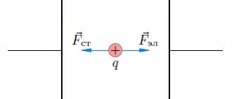
Let us consider in detail the case when a charged stationary conductor is in an external electrostatic field (created by extraneous stationary charges). In a conductor, sooner or later all charges will stop moving, and equilibrium will occur (since otherwise we would get a perpetual motion machine as a result of the continuous release of heat during the movement of charges). For such a charged conductor placed in an external electrostatic field, the statements given below will be valid.
Charge distribution in a conductor
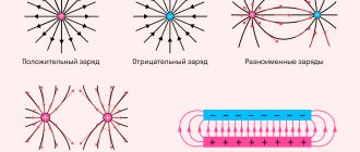
In order to answer the question about charge distribution in a conductor, we need to clarify some properties of the electrostatic field lines. Let us recall that the electric field line (including electrostatic) is an imaginary line in space, drawn so that the tangent to it at each point coincides with the vector of the electric field strength at this point. The experience of studying electrostatic fields gives reason to conclude that the lines of force of these fields are continuous and not closed, they can begin only on positive charges and end only on negative ones and cannot begin (end) at a point in space where there are no charges. When graphically depicting the field of a certain system of charges, the number of field lines starting or ending on any charge is proportional to the modulus of this charge. It follows that lines of force necessarily come out of (or enter into) any charge.
After what has been said about lines of force, let us return to the question of charge distribution in a conductor. Let us mentally select an arbitrary sufficiently small volume Δ V
inside the conductor (Fig. 1). Let's assume that this volume has a charge (to be specific, positive). Then lines of force will emerge from the selected volume, i.e., an electric field will exist near it. But there is no field inside the conductor. Therefore, the allocated volume must be neutral. And since we took this volume at an arbitrary place inside the conductor, we can say that the entire “inside” of the conductor is neutral and, therefore, the entire charge of the conductor is on its surface.
Rice. 1
Conducting sphere.
The field strength inside a charged conductor is zero. Otherwise, an electric force would act on the free charges inside the conductor, which would force these charges to move inside the conductor. This movement, in turn, would lead to heating of the charged conductor, which actually does not happen.
The fact that there is no electric field inside the conductor can be understood in another way: if there was one, then the charged particles would again move, and they would move exactly in such a way as to reduce this field to zero with their own field, because in fact, they would not want to move, because every system strives for balance. Sooner or later, all moving charges would stop exactly in that place so that the field inside the conductor would become zero.
On the surface of the conductor, the electric field strength is maximum. The magnitude of the electric field strength of a charged ball outside its boundaries decreases with distance from the conductor and is calculated using a formula similar to the formula for the field strength of a point charge, in which distances are measured from the center of the ball.
Since the field strength inside a charged conductor is zero, the potential at all points inside and on the surface of the conductor is the same (only in this case the potential difference, and therefore the voltage, is zero). The potential inside a charged ball is equal to the potential on the surface. The potential outside the ball is calculated using a formula similar to the formulas for the potential of a point charge, in which distances are measured from the center of the ball.
Electric capacity of a ball of radius R:
If the ball is surrounded by a dielectric, then:
Field outside a conductor near its surface
The vector of the electrostatic field strength at any point outside the conductor near its surface is directed perpendicular to the surface, which in other words can be said this way: the field lines enter and exit the conductor at right angles to the surface of the conductor. Otherwise, there would be a component of the field strength vector along the surface of the conductor, and a force with a component along the surface would act on the free charges on the surface of the conductor. As a result, charges would begin to move along the surface of the conductor, which would upset the balance.
Electric field energy
Let us assume that there is a certain volume of space that is “filled” with an electric field, that is, there is a source of the field, and thanks to long-range action we say that this space is filled with a field. Of course, in the form of matter there are no field lines of force, these are mental representations, but in this region of space any charge will react with the manifestation of the Coulomb force. Is it possible to somehow characterize this volume of space energetically? Since the electric field is potential, we can talk about its potential energy.
Let us assume that the above volume of space is volume V
inside a parallel-plate capacitor, and on the plates of the capacitor there is a
charge
Q. The potential difference between the plates is equal to Δφ
, then we can calculate the potential energy of the electric field using the following formula:
This formula is valid provided that the volume is a physical vacuum, that is, there are no physical particles there. If the space volume V
will be filled with a substance, then it is necessary
ε
(dielectric constant) by
ε
) that fills the volume
V.
The formula then looks like:
The example is given only for the field energy of a parallel-plate capacitor, this is just one case among many, but it makes it possible to see important significant relationships. For example, from the formula you can find out that one liter of volume (10-3 m3) at a voltage (potential difference) of 107 Volts is capable of storing only a small amount of energy, only 0.44 Joules. This value is for a vacuum, but there are substances that have a dielectric constant many times greater than unity. For water this value is 81, and for barium titanate it can reach up to 10,000. Accordingly, the stored energy increases by the same amount.
Date: 05/10/2015
Potential distribution in a conductor
Let us show that the potential difference of any two points of a conductor, including points on the surface, is equal to zero. Let there be arbitrary points M
and
K
inside the conductor.
Let us mentally transfer from point M
to point
K
a test charge
q
along a certain trajectory
MVC
lying inside the conductor (Fig. 2).
The field forces will not do work on the moving charge q
, since there is no field inside the conductor.
Therefore, the potential difference φ
M
φ
K = 0. If points
M
and
K
, one or both, lie on the surface of the conductor, then the proof that the potential difference between them is zero is similar.
Rice. 2
Since the potential difference of any two points on a conductor is zero, the potential of all points on the conductor, including points on the surface, is the same. Therefore, they talk about the potential of a conductor without indicating its specific point. Since all points on the surface of a conductor have the same potential, the surface of the conductor will be an equipotential surface.
INFOFIZ
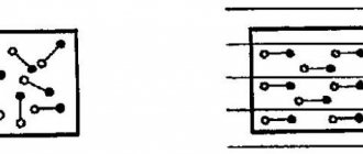
According to their electrical properties, all substances are divided into two large classes - substances that conduct electric current ( conductors ) and substances that do not conduct electric current ( dielectrics , or insulators).
We know that all substances are made up of atoms, which in turn are made up of charged particles. If there is no external field around a substance, then its particles are distributed so that the total electric field inside the substance is zero. If a substance is placed in an external electric field, then the field will begin to act on charged particles and they will be redistributed so that its own electric field will arise in the substance. The total electric field consists of the external field and the internal field created by charged particles of matter.
A conductor is a body or material in which electrical charges begin to move under the influence of an arbitrarily small force. Therefore, these charges are called free .
In metals, free charges are electrons, in solutions and melts of salts (acids and alkalis) - ions.
A dielectric is a body or material in which, under the influence of arbitrarily large forces, charges are displaced only by a small distance, not exceeding the size of an atom, relative to their equilibrium position. Such charges are called bound .
Let's take a closer look at these classes of substances.
Conductors in an electric field.
Conductors are substances that conduct electric current.
Typical conductors are metals.
The main feature
of conductors
is the presence
of free charges
(in metals these are electrons), which participate in thermal movement and can move throughout the entire volume of the conductor.
In the absence of an external field in any element of the volume of the conductor, the negative free charge is compensated by the positive charge of the ionic lattice. In a conductor introduced into an electric field, a redistribution of free charges occurs, as a result of which uncompensated positive and negative charges appear on the surface of the conductor. This process is called electrostatic induction
, and the charges that appear on the surface of the conductor are
inductive charges
.
The phenomenon of redistribution of charges inside a conductor under the influence of an external electric field is called
electrostatic induction .
Charges appearing on the surface of a conductor are called
induction charges
.
Induction charges create their own field, which compensates for the external field throughout the entire volume of the conductor:
(inside the conductor).
The total electrostatic field inside the conductor is zero, and the potentials at all points are the same and equal to the potential on the surface of the conductor.
Dielectrics in an electric field.
Dielectrics (insulators) are substances that do not conduct electric current.
Unlike conductors, dielectrics
(insulators) there are no free electric charges. They consist of neutral atoms or molecules. Charged particles in a neutral atom are bound to each other and cannot move under the influence of an electric field throughout the entire volume of the dielectric.
When a dielectric is introduced into an external electric field, a certain redistribution of the charges that make up the atoms or molecules occurs in it. As a result of such redistribution, excess uncompensated bonds
charges. All charged particles that form macroscopic bound charges are still part of their atoms.
Bound charges create an electric field, which inside the dielectric is directed opposite to the vector of the external field strength. This process is called dielectric polarization
.
Electric polarization
is a special state of a substance in which the electric moment of a certain volume of this substance is not equal to zero.
As a result, the total electric field inside the dielectric turns out to be less than the external field in absolute value.
A physical quantity equal to the ratio of the modulus of the external electric field strength in a vacuum to the modulus of the total field strength in a homogeneous dielectric is called
the dielectric constant of a substance .
The dielectric constant of a medium shows how many times the field strength in a vacuum is greater than in a dielectric.
This is a dimensionless quantity (there are no units of measurement).
When polarizing an inhomogeneous dielectric
bound charges can arise not only on surfaces, but also in the bulk of the dielectric.
In this case, the electric field of bound charges and the total field can have a complex structure, depending on the geometry of the dielectric. The statement that the electric field in a dielectric is ε times smaller in magnitude compared to the external field is strictly true only in the case of a homogeneous dielectric
that fills the entire space in which the external field is created. In particular:
If a homogeneous dielectric with dielectric constant ε contains a point charge q
, then the field strength
, created by this charge at a certain point, and the potential φ are ε times less than in vacuum:
There are several mechanisms for the polarization of dielectrics. The main ones are orientation
,
electronic
and
ion
polarization. The orientational and electronic mechanisms manifest themselves mainly during the polarization of gaseous and liquid dielectrics, and the ionic mechanisms - during the polarization of solid dielectrics.
If two conductors isolated from each other are given charges q
1 and
q
2, then a certain potential difference Δφ arises between them, depending on the magnitude of the charges and the geometry of the conductors.
The potential difference Δφ between two points in an electric field is often called voltage
and denoted by the
letter U.
Of greatest practical interest is the case when the charges of the conductors are identical in magnitude and opposite in sign: q
1 = –
q
2 =
q
.
In this case, we can introduce the concept of electrical capacitance
.
Electrical capacity (electrical capacity) of conductors
is a physical quantity that characterizes the ability of a conductor or a system of conductors to accumulate an electric charge.
Electrical capacity is found as the ratio of the charge q of one of the conductors to the potential difference Δφ between them :
In the SI system, the unit of electrical capacity is called the farad.
[
F
]:
The value of electrical capacity depends
on
the shape
and
size
of the conductors and on
the properties of the dielectric
separating the conductors.
There are configurations of conductors in which the electric field is concentrated (localized) only in a certain region of space. Such systems are called capacitors
, and the conductors that make up the capacitor are called
plates
.
The simplest capacitor is a flat capacitor
–
a system of two flat conducting plates located parallel to each other at a small distance compared to the size of the plates and separated by a dielectric layer
.
The electric field of a parallel-plate capacitor is mainly localized between the plates; however, a relatively weak electric field also arises near the edges of the plates and in the surrounding space, which is called the stray field
.
In a number of problems, one can approximately neglect the stray field and assume that the electric field of a flat capacitor is entirely concentrated between its plates.
The electrical capacity of a flat capacitor
is directly proportional to the area of the plates (plates) and inversely proportional to the distance between them
.
If the space between the plates is filled with a dielectric
, the electrical capacity of the capacitor increases by ε times:
Examples of capacitors with different plate configurations include spherical and cylindrical capacitors.
Spherical capacitor
is a system of two concentric conducting spheres of radii
R
1 and
R
2.
Cylindrical capacitor
conducting cylinders of radii
R
1 and
R
2 and length
L.
The capacitances of these capacitors filled with a dielectric with dielectric constant ε are expressed by the formulas:
- spherical capacitor
- cylindrical capacitor
To obtain a given capacitance value, capacitors are connected to each other, forming banks of capacitors
.
1) When connecting
capacitors , their similarly charged plates are connected.
The voltages on the capacitors are the same U
1 =
U
2 =
U,
charges are
q
1 = C1
U
and
q
2 =
C2 U.
Such a system can be considered as a single capacitor of electrical capacity C
, charged with charge
q
=
q
1 +
q
2 at a voltage between the plates equal
to U. This implies either C = C1 + C2
Thus , when connected in parallel, the electrical capacitances add up.
2) When capacitors are connected in series,
oppositely charged plates are connected.
The charges of both capacitors are the same q
1 =
q
2 =
q,
the voltages across them are equal and
Such a system can be considered as a single capacitor charged with charge q
at voltage between plates
U
=
U
1 +
U
2.
Therefore, or
When capacitors are connected in series, the reciprocal values of the capacitances are added.
The formulas for parallel and series connections remain valid for any number of capacitors connected to the battery.
Those. in the case of n capacitors of the same capacity C battery capacity
with parallel connection Comt = nC
with a serial connection Comt = C/n
If the plates of a charged capacitor are short-circuited with a metal conductor, then an electric current will flow through the circuit, the light bulb will light up and will remain on until the capacitor is discharged. This means that a charged capacitor contains a supply of energy.
The energy of a charged capacitor is equal to the work of external forces that must be expended to charge the capacitor.
The process of charging a capacitor can be represented as a sequential transfer of sufficiently small portions of charge Δ q
> 0 from one plate to the other. In this case, one plate is gradually charged with a positive charge, and the other – with a negative charge.
Since each portion is transferred under conditions when there is already some charge q
, and there is some potential difference between them
when transferring each portion Δ q
external forces must do work
Energy We
a capacitor of capacitance
C
charged with charge
q
can be found by integrating this expression over the range from 0 to
q
:
The formula expressing the energy of a charged capacitor can be rewritten in another equivalent form if we use the relation q
=
C.U.
.
Electrical energy We
should be considered as the potential energy stored in a charged capacitor.
According to modern concepts, the electrical energy of a capacitor is localized in the space between the plates of the capacitor, that is, in the electric field. Therefore it is called electric field energy
.
Cavity inside the conductor
Let's remove part of the substance from the inner region of the conductor. Since the substance being removed is neutral, it should be expected that the electrostatic field at all points outside the conductor, inside the conductor and in the resulting cavity will not change. And this will indeed be the case, and there will be no charges on the inner surface of the conductor (on the surface of the cavity). The entire charge of the conductor will be concentrated on the outer surface of the conductor, and the presence of a cavity inside the conductor will not affect the distribution of charge over the outer surface. There will be no field in the cavity or in the conductor. The potential of all points of the conductor and the cavity will be the same.
In short, a hollow conductor that has a charge and is placed in an external electrostatic field behaves in the same way as the corresponding solid one. We will not provide a proof of this statement, but note that it is confirmed by numerous experiments carried out by G. Cavendish (1731-1810) at the end of the 18th century and M. Faraday (1791-1867) at the beginning of the 19th century.