Types of Electronic Circuits
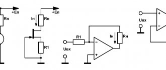
In radio electronics, there are several types of circuits: circuit diagrams, wiring diagrams, block diagrams, voltage and resistance maps.
Schematic diagrams
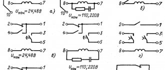
Such an electrical diagram gives a complete picture of all the functional components of the circuit, the types of connections between them, and the operating principle of electrical equipment. Circuit diagrams are commonly used in distribution networks. They are divided into two types:
- Single-line. This drawing shows only power circuits.
- Full. If the electrical installation is simple, then all its elements can be displayed on one sheet. To describe equipment that contains several circuits (power, measuring, control), drawings are made for each unit and placed on different sheets.
Block diagrams
In radio electronics, a block is an independent part of an electronic device. A block is a general concept; it can include both a small and a significant number of parts. A block diagram (or block diagram) gives only a general concept of the structure of an electronic device. It does not display: the exact composition of the blocks, the number of ranges of their functioning, the schemes according to which they are assembled. In a block diagram, blocks are represented by squares or circles, and the connections between them are represented by one or two lines.
The directions of signal passage are indicated by arrows. The names of the blocks in full or abbreviated form can be applied directly to the diagram. The second option is to number the blocks and decipher these numbers in a table located in the margins of the drawing. Graphic images of blocks can display the main parts or plot their operation.
Assembly
Wiring diagrams are convenient for creating an electrical circuit yourself. They indicate the location of each circuit element, communication methods, and the laying of connecting wires. The designation of radioelements on such diagrams usually approaches their natural appearance.
Voltage and resistance map
A voltage map (diagram) is a drawing in which, next to the individual parts and their terminals, the voltage values characteristic of the normal operation of the device are indicated. Voltages are placed in the gaps of the arrows, showing in which places measurements need to be made. The resistance map indicates the resistance values characteristic of a working device and circuits.
Voltage and resistance maps
Resistance map is a drawing that contains the resistance values of circuits and their elements during proper operation of electrical equipment, as well as between various specific points of the circuit without power sources and unscrewed lamps. When drawing up a map, the resistivity is measured with the power turned off and the capacitors discharged using an ohmmeter, a special device for measuring the resistance of elements of an electrical circuit. Subsequently, with the help of these map diagrams, the serviceability of the electrical circuit elements and their degree of wear are determined.
Resistance Map
The basis of the voltage map is a single-line voltage circuit diagram. All connecting lines in the form of wires are taken on top of it and voltage indicators, physical characteristics and voltage measurement locations are indicated. Then, using this map and electrical diagram, the voltage on the electrodes of the lamps, transistors and in other various nodes or entire sections of the electrical circuit will be checked.
Voltage map
Where to start reading diagrams?
In order to learn how to read circuits, first of all, we must study what a particular radio element looks like in a circuit. In principle, there is nothing complicated about this. The whole point is that if the Russian alphabet has 33 letters, then in order to learn the symbols of radio elements, you will have to try hard.
Until now, the whole world cannot agree on how to designate this or that radio element or device. Therefore, keep this in mind when you collect bourgeois schemes. In our article we will consider our Russian GOST version of the designation of radioelements
Resistors
Resistors include radio components that have a strictly defined resistance to the electric current flowing through them. This function is designed to reduce the current in the circuit. For example, to make a lamp shine less brightly, power is supplied to it through a resistor. The higher the resistance of the resistor, the less the lamp will glow. For fixed resistors, the resistance remains unchanged, while variable resistors can change their resistance from zero to the maximum possible value.
Each constant resistor has two main parameters - power and resistance. The power value is indicated on the diagram not with alphabetic or numerical symbols, but with the help of special lines. The power itself is determined by the formula: P = U x I, that is, equal to the product of voltage and current. This parameter is important because a particular resistor can only withstand a certain amount of power. If this value is exceeded, the element will simply burn out, since heat is released during the passage of current through the resistance. Therefore, in the figure, each line marked on the resistor corresponds to a certain power.
There are other ways to designate resistors in diagrams:
- On the circuit diagrams, the serial number is indicated in accordance with the location (R1) and the resistance value is equal to 12K. The letter “K” is a multiple prefix and means 1000. That is, 12K corresponds to 12,000 ohms or 12 kilo-ohms. If the letter “M” is present in the marking, this indicates 12,000,000 ohms or 12 megaohms.
- In marking with letters and numbers, the letter symbols E, K and M correspond to certain multiple prefixes. So the letter E = 1, K = 1000, M = 1000000. The decoding of the symbols will look like this: 15E - 15 Ohm; K15 – 0.15 Ohm – 150 Ohm; 1K5 – 1.5 kOhm; 15K – 15 kOhm; M15 – 0.15M – 150 kOhm; 1M2 – 1.5 mOhm; 15M – 15mOhm.
- In this case, only digital designations are used. Each includes three digits. The first two of them correspond to the value, and the third - to the multiplier. Thus, the factors are: 0, 1, 2, 3 and 4. They indicate the number of zeros added to the base value. For example, 150 - 15 Ohms; 151 – 150 Ohm; 152 – 1500 Ohm; 153 – 15000 Ohm; 154 – 120000 Ohm.
How are radioelements connected in a circuit?
So, it seems that we have decided on the task of this scheme. Straight lines are wires or printed conductors through which electric current will flow. Their task is to connect radioelements.
The point where three or more conductors connect is called a node. We can say that this is where the wiring is soldered:
If you look closely at the diagram, you can see the intersection of two conductors
Such intersection will often appear in diagrams. Remember once and for all: in this place the wires are not connected and they must be insulated from each other. In modern circuits, you can most often see this option, which already visually shows that there is no connection between them:
Here, it is as if one wire goes around the other from above, and they do not contact each other in any way.
If there was a connection between them, then we would see this picture:
Connection of capacitors
We can immediately distinguish three types (there are just so many) combinations of elements:
- Sequential - the total capacity of the entire chain is quite easy to calculate. In this case, it will be equal to the product of all the capacities of the elements divided by their sum.
- Parallel - in this case, calculating the total capacity is even easier. It is necessary to add up the capacitances of all capacitors in the chain.
- Mixed - in this case, the scheme is divided into several parts. We can say that it is simplified - one part contains only elements connected in parallel, the second - only in series.
And this is just general information about capacitors; in fact, you can talk a lot about them, citing interesting experiments as examples.
Reading an Electrical Diagram
The diagram itself, on which the symbols are drawn, is called a schematic diagram. It not only shows how certain elements of the circuit are connected, but also explains how the entire device works, showing the principle of its operation. To achieve this result, it is important to correctly show the individual groups of elements and the connection between them.
In addition to the fundamental one, there are also installation ones. They are designed to accurately display each element in relation to each other. The arsenal of radioelements is huge. New ones are constantly being added. Nevertheless, the UGO in all diagrams is almost the same, but the letter code is significantly different. There are 2 types of standard:
- state, this standard may include several states;
- international, used almost all over the world.
But whatever standard is used, it must clearly show the designation of radio components on the diagram and their name. Depending on the functionality, UGO radio components can be simple or complex. For example, several conditional groups can be distinguished:
- power supplies;
- indicators, sensors;
- switches;
- semiconductor elements.
This list is incomplete and serves for illustrative purposes only. To make it easier to understand the symbols of radio components in the diagram, you need to know the principle of operation of these elements.
Conditions for designating radio components
A correct electrical diagram can not only tell you how to connect its elements, but also explain the principle of operation to a knowledgeable person. Graphic symbols in circuit design are accepted by global standards, so they are the same almost everywhere. But the letter code of an element may differ greatly from the state one. Therefore, the following is important for any electrical circuit:
- certain type;
- characteristic audience;
- creation path (manually or on a printing press);
- operating conditions of electrical equipment;
- availability of installation repairs.
Confusing electrical circuit
This article does not talk about how to correctly identify radio components by appearance alone. We will talk about circuit design and symbols of resistors, transistors, etc.
Domestic marking of microcircuits
Typical markings of domestic microcircuits are as follows: KR580VG80A.
The first letter indicates the specifics of the microcircuit:
K – orientation to the mass market; E – export version.
If the first letter is missing, the chip is highly specialized and configured for special tasks.
The second letter in the microcircuit marking indicates the type of case:
A – plastic (compact); B – absent (unpackaged microcircuit); E – DIP (metal); M – metal ceramics; N – metal ceramics (compact); P – DIP (plastic).
The number following the housing type characterizes whether the microcircuit belongs to one or another design and technical group.
1, 4, 8 – hybrid chips; 1, 5, 6, 7 – semiconductor chips; 3 – film version.
The next two digits indicate the series number.
The letters following the series indicate the functional purpose of the microcircuit.
A – shapers; B – delay modules; BM – passive electronic component; BR – active electronic component; B – computing module; G – pulse generator; EP – power source; I – digital electronic components; K – switching modules; H – bundles of components; P – various types of converters; P – storage modules; U – amplifiers; F – filters; X – multifunctional microcircuits.
The serial number of the series is followed by the development number (two-digit or single-digit).
The last symbol in the microcircuit marking indicates any features in its electrical characteristics.
Foreign marking of microcircuits (using the Pro Electron system)
In Europe and the West, there are several established labeling schemes for electronic components, each of which has minor differences in its field of application. But the basic principles remain common to all, and they are all listed in the classification adopted by the international Pro Electron association.
According to the Pro Electron classification, the marking of microcircuits consists of three alphabetic symbols followed by a numerical value.
The first letter indicates the method of signal conversion in the circuit:
T – analog conversion; S – digital conversion; U – mixed type transformation.
The second letter after the type of signal conversion does not have any fixed meaning (it is selected by the manufacturer). The exception is the letter “H”, which always denotes the hybrid operating principle of the chip.
In the case of digital electronic components, the first two letters indicate the features of the device:
FY – ESL line; GA – low-current TTL chips; GF – standard TTL; GJ – productive TTL; H – complementary microcircuits.
The third symbol in the microcircuit marking indicates the range of its operating temperatures:
A) not nominated; B) from 0 to +70 °C; C) from -55 to +125 °C; D) from -25 to +70 °C; E) from -25 to +85 °C; F) from -40 to +85 °C; G) from -55 to + 85 °C.
After the letter indicating the temperature range, there is a four-digit number - this is the serial number of the chip.
Following the serial number, the type of case is indicated in the microcircuit marking. This designation can be two-letter or one-letter.
The meaning of the first letter in two-letter markings:
C – cylindrical body; D – DIP housing (contacts are located in two rows along the edges of the microcircuit); E – DIP housing with heat dissipator; F – quadrangular flat (double-sided placement of contacts); G – quadrangular flat (four-sided placement of contacts); K – TO-3 body; M – multi-row body; Q – symmetrical arrangement of contacts along four edges; R – housing with a four-row arrangement of contacts and an external heat dissipator; S – contacts are placed in one row; T – housing with three-row arrangement of contacts.
We recommend reading: Etching boards
The meaning of the second letter in two-letter markings:
G – glass ceramics; M – metal; P – plastic; X – other materials.
If the serial number in the microcircuit marking is followed by one letter, it should be interpreted as follows:
C – cylindrical body; D – ceramic body; F – flat body; P – DIP plastic housing; Q – four-row arrangement of contacts; T – miniature plastic case; U – unpackaged integrated circuit.
The next two digits after the housing type are the serial number of the electronic component. The last number in the microcircuit marking is its operating temperature range. It should be interpreted as follows:
0) not nominated; 1) from 0 to +70 °C; 2) from -55 to +125 °C; 3) from -10 to +85 °C; 4) from +15 to +55 °C; 5) from -25 to +70 °C; 6) from -40 to + 85 °C.
We hope this information will help you understand the variety of markings, and you can easily select and buy microcircuits with the desired characteristics.
Letter abbreviations for radio electronics
| Letter abbreviation | Decoding the abbreviation |
| A.M. | amplitude modulation |
| AFC | automatic frequency adjustment |
| APCG | automatic local oscillator frequency adjustment |
| APChF | automatic frequency and phase adjustment |
| AGC | automatic gain control |
| ARYA | automatic brightness adjustment |
| AC | acoustic system |
| AFU | antenna-feeder device |
| ADC | analog-to-digital converter |
| frequency response | amplitude-frequency response |
| BGIMS | large hybrid integrated circuit |
| NOS | wireless remote control |
| BIS | large integrated circuit |
| BOS | signal processing unit |
| BP | power unit |
| BR | scanner |
| DBK | radio channel block |
| BS | information block |
| BTK | blocking transformer personnel |
| BTS | blocking transformer line |
| BOO | Control block |
| BC | chroma block |
| BCI | integrated color block (using microcircuits) |
| VD | video detector |
| VIM | time-pulse modulation |
| VU | video amplifier; input (output) device |
| HF | high frequency |
| G | heterodyne |
| GW | playback head |
| GHF | high frequency generator |
| GHF | hyper high frequency |
| GZ | start generator; recording head |
| GIR | heterodyne resonance indicator |
| GIS | hybrid integrated circuit |
| GKR | frame generator |
| GKCH | sweep generator |
| GMW | meter wave generator |
| GPA | smooth range generator |
| GO | envelope generator |
| HS | signal generator |
| GSR | line scan generator |
| gss | standard signal generator |
| yy | clock generator |
| GU | universal head |
| VCO | voltage controlled generator |
| D | detector |
| dv | long waves |
| dd | fractional detector |
| days | voltage divider |
| dm | power divider |
| DMV | decimeter waves |
| DU | remote control |
| DShPF | dynamic noise reduction filter |
| EASC | unified automated communication network |
| ESKD | unified system of design documentation |
| zg | audio frequency generator; master oscillator |
| zs | slowing system; sound signal; pickup |
| AF | audio frequency |
| AND | integrator |
| ICM | pulse code modulation |
| ICU | quasi-peak level meter |
| ims | integrated circuit |
| ini | linear distortion meter |
| inch | infra-low frequency |
| and he | reference voltage source |
| SP | power supply |
| ichh | frequency response meter |
| To | switch |
| KBV | traveling wave coefficient |
| HF | short waves |
| kWh | extremely high frequency |
| KZV | recording-playback channel |
| CMM | pulse code modulation |
| kk | frame deflection coils |
| km | coding matrix |
| cnc | extremely low frequency |
| efficiency | efficiency |
| KS | deflection system line coils |
| ksv | standing wave ratio |
| ksvn | voltage standing wave ratio |
| CT | check Point |
| KF | focusing coil |
| TWT | traveling wave lamp |
| lz | delay line |
| fishing | back wave lamp |
| LPD | avalanche diode |
| lppt | tube-semiconductor TV |
| m | modulator |
| M.A. | magnetic antenna |
| M.B. | meter waves |
| TIR | metal-insulator-semiconductor structure |
| MOP | metal-oxide-semiconductor structure |
| ms | chip |
| MU | microphone amplifier |
| neither | nonlinear distortion |
| LF | low frequency |
| ABOUT | common base (switching on a transistor according to a circuit with a common base) |
| VHF | very high frequency |
| oi | common source (turning on the transistor *according to a circuit with a common source) |
| OK | common collector (switching on a transistor according to a circuit with a common collector) |
| onch | very low frequency |
| oos | negative feedback |
| OS | deflection system |
| OU | operational amplifier |
| OE | common emitter (connecting a transistor according to a circuit with a common emitter) |
| Surfactant | surface acoustic waves |
| pds | two-speech set-top box |
| Remote control | remote control |
| pcn | code-voltage converter |
| pnc | voltage-to-code converter |
| PNC | converter voltage frequency |
| village | positive feedback |
| PPU | noise suppressor |
| pch | intermediate frequency; frequency converter |
| ptk | tv channel switch |
| PTS | full TV signal |
| Vocational school | industrial television installation |
| PU | preliminary effort |
| PUV | playback pre-amplifier |
| PUZ | recording pre-amplifier |
| PF | bandpass filter; piezo filter |
| ph | transfer characteristic |
| pcts | full color television signal |
| Radar | line linearity regulator; radar station |
| RP | memory register |
| RPCHG | manual adjustment of local oscillator frequency |
| RRS | line size control |
| PC | shift register; mixing regulator |
| RF | notch or stop filter |
| REA | radio-electronic equipment |
| SBDU | wireless remote control system |
| VLSI | ultra-large scale integrated circuit |
| NE | medium waves |
| SVP | touch program selection |
| Microwave | ultra high frequency |
| sg | signal generator |
| SDV | ultralong waves |
| SDU | dynamic light installation; remote control system |
| SK | channel selector |
| SLE | all-wave channel selector |
| sk-d | UHF channel selector |
| SK-M | meter wave channel selector |
| CM | mixer |
| ench | ultra-low frequency |
| JV | grid field signal |
| ss | clock signal |
| ssi | horizontal clock pulse |
| SU | selector amplifier |
| sch | average frequency |
| TV | tropospheric radio waves; TV |
| TVS | line output transformer |
| tvz | audio output channel transformer |
| tvk | output frame transformer |
| TIT | television test chart |
| TKE | temperature coefficient of capacitance |
| tka | temperature coefficient of inductance |
| tkmp | temperature coefficient of initial magnetic permeability |
| tkns | temperature coefficient of stabilization voltage |
| tks | temperature coefficient of resistance |
| ts | network transformer |
| shopping center | television center |
| tsp | color bar table |
| THAT | technical specifications |
| U | amplifier |
| UV | playback amplifier |
| UVS | video amplifier |
| UVH | sample-hold device |
| UHF | high frequency signal amplifier |
| UHF | UHF |
| UZ | recording amplifier |
| Ultrasound | audio amplifier |
| VHF | ultrashort waves |
| ULPT | unified tube-semiconductor TV |
| ULLTST | unified lamp-semiconductor color TV |
| ULT | unified tube TV |
| UMZCH | audio power amplifier |
| CNT | unified TV |
| ULF | low frequency signal amplifier |
| UNU | voltage controlled amplifier. |
| UPT | DC amplifier; unified semiconductor TV |
| HRC | intermediate frequency signal amplifier |
| UPCHZ | intermediate frequency signal amplifier? |
| UPCH | intermediate frequency image amplifier |
| URCH | radio frequency signal amplifier |
| US | interface device; comparison device |
| USHF | microwave signal amplifier |
| USS | horizontal sync amplifier |
| USU | universal touch device |
| UU | control device (node) |
| UE | accelerating (control) electrode |
| UEIT | universal electronic test chart |
| PLL | phase automatic frequency control |
| HPF | high pass filter |
| FD | phase detector; photodiode |
| FIM | pulse phase modulation |
| FM | phase modulation |
| LPF | low pass filter |
| FPF | intermediate frequency filter |
| FPCHZ | audio intermediate frequency filter |
| FPCH | image intermediate frequency filter |
| FSI | lumped selectivity filter |
| FSS | concentrated selection filter |
| FT | phototransistor |
| FCHH | phase-frequency response |
| DAC | digital-to-analog converter |
| Digital computer | digital computer |
| CMU | color and music installation |
| DH | central television |
| BH | frequency detector |
| CHIM | pulse frequency modulation |
| world championship | frequency modulation |
| shim | pulse width modulation |
| shs | noise signal |
| ev | electron-volt (e•V) |
| COMPUTER. | electronic computer |
| emf | electromotive force |
| ek | electronic switch |
| CRT | cathode-ray tube |
| AMY | electronic musical instrument |
| emos | electromechanical feedback |
| EMF | electromechanical filter |
| EPU | record player |
| Digital computer | electronic digital computer |
Other items
All radio components are connected to each other by conductors. In the diagram they are depicted as straight lines and drawn strictly horizontally and vertically. If the conductors have an electrical connection when crossing each other, then a dot is placed at this place. In Soviet and American diagrams, to show that the conductors are not connected, a semicircle is placed at the intersection.
To designate variable capacitors, an arrow is used; it crosses out the capacitor diagonally. In trimmers, a T-shaped sign is used instead of an arrow. Varicond - a capacitor that changes capacitance depending on the applied voltage, is drawn like an alternating one, but the arrow is replaced by a short straight line, next to which there is the letter u. The capacitance is shown with a number and a microFarad (microFarad) is placed next to it. If the capacity is smaller, the letter code is omitted.
Another element that no electrical circuit can do without is a resistor. Indicated in the diagram as a rectangle. To show that the resistor is variable, an arrow is drawn on top. It can be connected either to one of the pins, or be a separate pin. For trimmers, a sign in the form of the letter t is used. As a rule, its resistance is indicated next to the resistor.
Symbols in the form of dashes can be used to indicate the power of fixed resistors. A power of 0.05 W is indicated by three oblique, 0.125 W - two oblique, 0.25 W - one oblique, 0.5 W - one longitudinal. High power is shown in Roman numerals. Due to the diversity, it is impossible to describe all the designations of electronic components on the diagram. To identify a particular radio element, use reference books.
Permanent capacitors
Graphic symbols for capacitors with constant capacitance are widely used in electrical circuit diagrams. They are depicted as two parallel segments and conclusions from the middle of each of them. The letter C is placed next to the icon, after it - the serial number of the element and, with a small interval, a numerical designation of the nominal capacity.
When using a capacitor with an approximate capacitance in a circuit, an asterisk is placed instead of its serial number. The rated voltage value is indicated only for high voltage circuits. This applies to all capacitors except electrolytic ones. The digital voltage symbol is placed after the capacity designation.
The connection of many electrolytic capacitors requires correct polarity. In the diagrams, a “+” sign or a narrow rectangle is used to indicate a positive cover. In the absence of polarity, narrow rectangles mark both plates.
Features of reading circuits
In circuit diagrams, conductors (or tracks) are indicated by lines.
This designates conductors that intersect, but they do not have a common connection and are not electrically connected to each other.
And this is what they look like if there is a connection between them. The black dot is a node in the circuit. A node is a connection of several conductors or parts together. They are electrically connected to each other.
Common point
Beginner radio amateurs often have a question: what is this symbol on the diagram?
This is the common point (GND, ground). Previously, it was called the common wire. This is how a single power wire is designated. Usually this is a minus of nutrition. Previously, in the diagrams they could make the common wire and the power plus. In this case, the diagram without a common point would look like this:
A common point with unipolar power supply looks visually better and more compact than if you simply make a single line between them.
It is also called a common point because any other points on the diagrams can be measured relative to it. For example, place the multimeter probe on a common point, and with the second probe you can check any part of the circuit in the diagram.
Why can it be called ground (GND)? Previously, the chassis of the device body could be used as a common wire. This has caused confusion between grounding and earth. It is interpreted in the context of the schema. The circuit that was discussed above - the common point (ground) is simply a minus of the power supply. Another thing is bipolar current sources and grounding.
Bipolar power supply and common point
In a bipolar supply, the common point is the middle contact between plus and minus.
Grounding
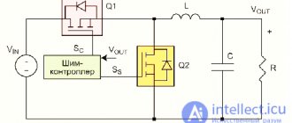
An example of grounding would be a filter in computer power supplies.
From the capacitor filter, noise goes to the power supply housing. This is grounding. And from the power supply they must go into the outlet if you have a ground connection, otherwise the body of the power supply itself may be energized. The currents there are not large, they are not life-threatening. This is done to reduce impulse noise in the power supply and safety.
Sometimes in power supplies, instead of the housing, noise from the capacitor goes to a common point. It all depends on the design and circuitry. In this case, there will be more interference than with grounding.
In general, there are different grounding connections on the diagrams. For example, in digital technology, analog ground is separated from digital ground. so as not to disrupt the operating modes of the circuit. Pulse noise can affect the analog part of the circuit.
Transistors
If diodes and zener diodes can sometimes not even be found in designs, then you will find transistors in any (except for a detector receiver). Transistors have three electrodes:
- Base (abbreviated as “B”).
- Collector (K).
- Emitter (E).
Transistors can operate in several modes, but most often they are used in amplification and switch modes (like a switch). A comparison can be made with a megaphone - they shouted into the base, and an amplified voice flew out of the collector. And hold the emitter with your hand - this is the body. The main characteristic of transistors is the gain (ratio of collector and base current). It is this parameter, along with many others, that is basic for this radio component. The symbols on the diagram for a transistor are a vertical line and two lines approaching it at an angle. There are several most common types of transistors:
- Polar.
- Bipolar.
- Field.
There are also transistor assemblies consisting of several amplification elements. These are the most common radio components that exist. The designations on the diagram were discussed in the article.
How to learn to read circuit diagrams
There are really only a few ways. This is theory and practice. If you learn the designation of radio components, this does not mean that you have learned circuit design. It's like learning your ABC's, but without grammar and practice you won't learn the language.
Theory is circuit design, books, a description of the principle of operation of the circuit. Practice involves assembling devices, repairing and soldering.
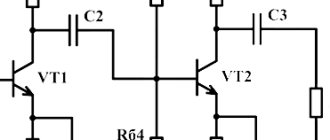
For example, a simple amplifier circuit with one transistor.
Input X1 plus (left or right channel), X2 minus. The sound signal is sent to electrolytic capacitor C1. It protects transistor VT1 from short circuiting, since transistor VT1 is constantly open using a voltage divider across R1 and R2. The voltage divider sets the operating point at the base of transistor VT1, and the transistor does not distort the input signal. Resistor R3 and capacitor C2, which are connected to the emitter of transistor VT1, perform the function of thermal stabilization of the operating point as the temperature of the transistor increases. Electrolytic capacitor C3 accumulates and filters the supply voltage. The BF1 dynamic head serves as an audio signal output.
Is it possible to understand this only by learning the designations of radio components without circuit design and theory? Unlikely.
The situation is even more complicated with digital technology.
What kind of microcontroller is this, what functions does it perform, what firmware and what fuses are installed in it? And the second microcircuit, what amplifier is it? Without datasheets and a description of the circuit, it will not be possible to understand its operation.
Study circuit design, theory and practice. Simply learning the names of the parts will not help you understand the circuitry. The designation of radio components can be learned on its own with practice and accumulation of knowledge. It all depends on the chosen industry. Signalmen have one circuit design, mobile equipment repairmen have another. And those who deal with sound will not really understand electricians. As well as vice versa. To understand another industry, its circuitry and operating principles, you need to immerse yourself in it.
Circuit diagrams are a kind of language that has different dialects.
Therefore, one should not create illusions. Study circuit design and assemble circuits.
Recommended reading: Debug board
Schematic diagrams help to assemble devices, and when studying the theory, to understand the operation of the device. Without knowledge and experience, a diagram is just a diagram.
Designations of radio components on circuit diagrams
UGO is a conditionally graphic image of a radio component on a diagram. Some UGOs differ from each other.
For example, in the USA the designation of resistors differs from the CIS and Europe.
Because of this, the perception of the scheme changes.
However, in appearance and in designations they are similar. Or, for example, transistors. Somewhere they are drawn with circles, and somewhere without. The size and angle of the arrows may vary. The table shows the UGO of domestic radio components.
UGOName
NPN bipolar transistor PNP bipolar transistor N-base unijunction transistor P-base unijunction transistor Relay winding Grounding Diode Diode bridge Schottky diode Double-node zener diode Bidirectional zener diode Reversing diode Zener diode Tunnel diode Varicap Inductor Inductor with adjustable core Inductor with core Classic transformer Winding Adjustable core Electrolytic capacitor Non-polar capacitor Reference capacitor Variable capacitor Trimmer capacitor On-off switch Reed switch Open switch Close switch N-channel FET FET p-channel Fast-acting fuse Time-lag fuse Fuse Breakdown fuse Thermal coil Refractory fuse Switch-fuse Arrester Arrester two-electrode Electrochemical spark gap Ion spark gap Horn spark gap Symmetrical spark gap Three-electrode spark gap Tubular spark gap Carbon spark gap Vacuum spark gap Valve spark gap Telephone socket Connector Connector Variable resistor Trimmer resistor Resistor 0.125 W resistor 0.25 W resistor 0.5 W resistor 1 W resistor Re resistor 2 W Resistor 5 W Reverse-conducting dinistor Reverse-turn-on dynistor Diode symmetrical thyristor Tetrode thyristor Cathode-controlled thyristor Anode-controlled thyristor Cathode-controlled thyristor Triode symmetrical thyristor Anode-controlled turn-off thyristor Cathode-controlled thyristor Diode optocoupler Photodiode Photothyristor Phototransistor Resistive optocoupler LED Thyristor optocoupler These are not all the details. And there is no particular point in cramming them. Such tables are useful in the form of a reference book. You can identify what kind of part is shown on the diagram while studying it or assembling the device.
Types of radio components
Resistor - what is it and what is it for?
Based on functionality, radio components are divided into the following components.
Resistors and their types
Resistance is needed to limit the current in electrical circuits, and it also creates a voltage drop in a separate section of the electrical circuit.
The resistor is characterized by three parameters:
- nominal resistance;
- power dissipation;
- tolerance
Nominal resistance
This value is indicated in Ohms and its derivatives. The resistance value for radio resistors ranges from 0.001 to 0.1 Ohm.
Power dissipation
If the current exceeds the rated value for a particular resistor, it may burn out. If a current of 0.1 A flows through a resistance, its received power must be at least 1 W. If you install a part with a power of 0.5 W, it will quickly fail.
Tolerance
The resistance tolerance value is assigned to the resistor by the manufacturer. Production technology does not allow achieving absolute accuracy of the resistance value. Therefore, resistors have tolerances for parameter deviation in one direction or another.
For household appliances, the tolerance can be from – 20% to + 20%. For example, a 1 ohm resistor may actually be 0.8 or 1.2 ohms. For high-precision systems used in the military and medical fields, the tolerance is 0.1-0.01%.
Resistor color coding
Types of resistance
In addition to the usual resistances installed on boards, there are resistors such as:
- Variables;
- SMD resistors.
Variables (tuning)
A clear example of a variable resistance is the sound volume control in any household radio equipment. Inside the housing there is a graphite disk along which the current extractor moves. The position of the puller regulates the resistance value of the area of the disk through which the current passes. Due to this, the resistance in the circuit changes and the volume level changes.
SMD resistors
In computers and similar equipment, resistors are installed on SMD boards. Chips are made using film technology. The resistance parameter depends on the thickness of the resistive film. Therefore, products are divided into two types: thick-film and thin-film.
Capacitors
The radio element accumulates electrical charge, separating the alternating and direct current components, filtering the pulsating flow of electrical energy. The capacitor consists of two conductive plates, between which a dielectric is inserted. Air, cardboard, ceramics, mica, etc. are used as gaskets.
Electrolytic capacitors
The characteristics of the radio component are:
- nominal capacity;
- Rated voltage;
- tolerance
Nominal capacity
The capacitance of capacitors is expressed in microfarads. The capacity value in these units of measurement is usually displayed as a number on the body of the part.
Rated voltage
The voltage designation of radio components gives an idea of the voltage at which the capacitor can perform its functions. If the permissible value is exceeded, the part will be broken. A damaged capacitor will become a simple conductor.
Tolerance
The permissible voltage fluctuation reaches 20-30% of the nominal value. This approval is permitted for the use of radio components in household equipment. In high-precision devices, the permissible voltage change is no more than 1%.
Acoustics
Acoustic elements include speakers of various configurations. They are all united by a single structural principle. The purpose of loudspeakers is to convert changes in the frequency of electrical current into sound vibrations in the air.
Interesting. Dynamic direct radiation heads are built into radio devices in all areas of human activity.
The main acoustic parameters are as follows.
Nominal resistance
The amount of electrical resistance can be determined by measuring the speaker's voice coil with a digital multimeter. It is a regular inductor. Most acoustic sound devices have an impedance ranging from 2 to 8 ohms.
Frequency range
Human hearing is susceptible to sound vibrations ranging from 20 Hz to 20,000 Hz. One acoustic device cannot reproduce this entire range of sound frequencies. Therefore, for ideal sound reproduction, speakers are made of three types: low-frequency, mid-range and high-frequency loudspeakers.
Attention! Different frequency sound heads are combined into a single acoustic system (speakers). Each speaker reproduces sounds in its own range, resulting in perfect sound.
Power
The power level of each specific speaker is indicated on its back side in Watts. If an electrical impulse exceeding the rated power of the device is applied to the dynamic head, the speaker will begin to distort the sound and will soon fail.
Diodes
A revolution in the production of radio receivers in the last century was made by diodes and transistors. They replaced bulky radio tubes. The radio component represents a shut-off device similar to a water tap. The radio element acts in one direction of electric current. That's why it is called a semiconductor.
Diodes and transistors
Electrical quantity meters
The parameters characterizing electric current include three indicators: resistance, voltage and current. Until recently, bulky instruments such as ammeter, voltmeter and ohmmeter were used to measure these quantities. But with the advent of the era of transistors and microcircuits, compact devices appeared - multimeters, which can determine all three current characteristics.
Important! A radio amateur should have a multimeter in his arsenal. This universal device allows you to test radio elements and measure various characteristics of the passing current in all areas of the radio circuit.
Connectors
To connect circuit components without soldering, various types of connectors are used. Radio equipment manufacturers use compact contact connection designs.
Connectors
Switches
Functionally, they perform the work of the same connectors. The difference is that turning off and turning on the electrical flow is done without violating the integrity of the electrical circuit.
Ratings of radio components
In general, there are disagreements in this regard. According to GOST at the moment, the nominal values of parts are not indicated on circuit diagrams. This is done in order not to clutter the diagram with information.
The circuit diagram is accompanied by a list of parts, wiring and structural diagrams, as well as a printed circuit board.
There is another generally accepted standard. The diagrams indicate the ratings of some parts and their operating voltages.
For example, in this circuit there are two resistors.
By default, resistance without a prefix is written only as a number. R2 has a resistance of 220 Ohms. And R3 has a letter after the number. The resistance of this resistor reads 2.2k ohms (2,200 ohms).
Consider two capacitors in the diagram.
In this case, C5 is a non-polar capacitor with a capacitance of 0.01 µF. Microfarads can be designated either uF or uF. And capacitor C6 is polar and electrolytic. This is indicated by the plus sign near the UGO. Capacitance C6 is 470 μF. The rated operating voltage is indicated in volts. Here for C6 it is 16 V.
Nanofarads are denoted as nF.
If there is no microfarad (uF) or nanofarad (nF) prefix on the circuit, then the capacitance of this capacitor is measured in picofarads (pF, pF). This condition is not common, so carefully study the diagram you are about to read or assemble. There are few capacitances in farads (F), so µF, nF and pF are used.
Main types of SMD components
Let's look at the main SMD elements used in our modern devices. Resistors, capacitors, low-value inductors, fuses, diodes and other components look like ordinary small rectangles, or rather, parallelepipeds))
On boards without a circuit, it is impossible to know whether it is a resistor, a capacitor, or even a coil. The Chinese mark as they please. On large SMD elements, they still put a code or numbers to determine their identity and value. In the photo below these elements are marked in a red rectangle. Without a diagram, it is impossible to say what type of radio elements they belong to, as well as their rating.
The standard sizes of SMD components may be different. Here is a description of the standard sizes for resistors and capacitors. Here, for example, is a yellow rectangular SMD capacitor. They are also called tantalum or simply tantalum:
And this is what SMD transistors look like:
There are also these types of SMD transistors:
Inductors, which have a high rating, in SMD version look like this:
And of course, how can we live without microcircuits in our age of microelectronics! There are many SMD types of chip packages, but I divide them mainly into two groups:
1) Microcircuits in which the pins are parallel to the printed circuit board and are located on both sides or along the perimeter.
2) Microcircuits in which the pins are located under the microcircuit itself. This is a special class of microcircuits called BGA (from the English Ball grid array - an array of balls). The terminals of such microcircuits are simple solder balls of the same size.
The photo below shows a BGA chip and its reverse side, consisting of ball pins.
BGA chips are convenient for manufacturers because they greatly save space on the printed circuit board, because there can be thousands of such balls under any BGA chip. This makes life much easier for manufacturers, but does not make life any easier for repairmen.
Classification of radioelements
Systematization of electronic components is necessary so that a radio technician and electronics engineer can freely navigate the selection of radio components for the creation and repair of circuit boards for radio devices. The classification of names and types of radio components is carried out in three directions:
- CVC;
- installation method;
- appointment.
CVC
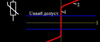
The three-letter abbreviation VAC stands for current-voltage characteristic. The current-voltage characteristic reflects the dependence of the current on the voltage flowing in any radio component. The characteristics appear in the form of graphs, where current values are plotted along the ordinate, and voltage values are noted along the abscissa. Based on the shape of the graph, radio components are divided into passive and active elements.
Passive
Radio components whose characteristics look like a straight line are called linear or passive radio elements. Passive parts include:
- resistors (resistance);
- capacitors (capacities);
- chokes;
- relays and solenoids;
- inductive coils;
- transformers;
- quartz (piezoelectric) resonators.
Active
Elements with nonlinear characteristics include:
- transistors;
- thyristors and triacs;
- diodes and zener diodes;
- photovoltaic cells.
The characteristics expressed on the graphs by a curved function refer to nonlinear radioelements.
I-V curves of linear and nonlinear radio components
Installation method
Based on the installation method, they are divided into three categories:
- installation by volumetric soldering;
- surface mounting on printed circuit boards;
- connections using connectors and sockets.
Purpose
According to their purpose, radioelements can be divided into several groups:
- functional parts fixed on boards (the above components);
- display devices, these include various displays, indicators, etc.;
- acoustic devices (microphones, speakers);
- vacuum gas discharge: cathode ray tube, octodes, traveling and backward wave lamps, LEDs and LCD screens;
- thermoelectric parts – thermocouples, thermistors.