LED chandelier with remote control in all its glory
This article is devoted to how to properly connect and secure a ceiling LED chandelier with a control panel.
I described in detail the repair of such chandeliers in another article, please read it.
Such chandeliers appeared on sale several years ago, people buy them willingly, the device is relatively complex (for a chandelier), so the topic is relevant.
I will not describe why such ceiling chandeliers are needed and how good they are, as is usually done in such articles. I'll get straight to the point.
I have already published several articles on chandeliers on SamElectric, and I will provide links along the way.
Installation and fixation of LED chandelier
LED chandeliers with remote control, like other types of lamps, are attached to the ceiling using standard installation devices supplied in the kit. In most cases, this is a strip that must be secured to the ceiling using dowels. They often also come included. If they are not there, which is typical for the cheapest Chinese chandeliers, then you need to purchase fasteners separately.
Attaching the chandelier to the bar.
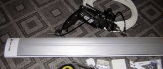
Holes for installing any LED chandelier are drilled in the ceiling using a drill equipped with concrete drills. First, the strip is secured to the dowels, then the lamp is attached to it. The order of work depends on the design of the chandelier and is almost always described in the instructions.
A strip fixed to the ceiling.
If the chandelier is large and heavy, it is better to hang it on a hook. Older houses already have such hooks.
Hook for hanging lamps.
For hanging serious chandeliers in more modern homes, you can purchase an anchor with a hook. It expands in the drilled hole and can withstand heavy loads.
Anchor with hook for hanging heavy lamps.
Read more about installation methods: Mounting and installing a chandelier
Some tips for purchasing a ceiling lamp
In order for an LED chandelier to enjoy uninterrupted operation for a long time, when choosing it you should pay attention to some nuances:
- First you need to inspect the packaging. A self-respecting manufacturing company will not put the product in a faceless gray box - it should be of good quality and dense. It must contain details, a link to the website, and contact numbers.
- It is mandatory to check two main documents - certificates of conformity and quality. And if the second one can be compiled according to the standards of the manufacturing country, then the second one must necessarily be marked with Russia.
- You should check that the warranty card is filled out correctly. It contains marks on the date of sale, the seal and signature of the seller.
- You must save the cash receipt - without it, you can forget about repairs under warranty.
Wiring diagram
To connect any chandelier, it is not necessary to know its internal structure. A chandelier with a remote control is connected to the network like a regular lamp:
- phase wire to terminal L;
- zero to terminal N;
- if there is a protective conductor, it is connected to the terminal marked with PE or the earth symbol.
Connection diagram for a luminaire via a single-key switch using a distribution box.
The diagram for connecting the lamp as a “black box” using a junction box is shown in the figure. The wall light switch is the main one. If it is turned off, the remote control will not affect the operation of the lighting in any way.
Important! If a lamp of protection class 1 is used, then protective grounding is the only (in addition to the main insulation) measure of protection against electric shock in the event of breakdown of the insulating layer. It cannot be used in TN-C networks - it will work, but will not provide security.
But knowledge of the internal structure will not be superfluous for understanding the operation of the device as a whole, as well as for performing repair work, if necessary.
Block diagram of a chandelier with remote control.
Most chandeliers controlled by remote control contain a remote control module that switches loads, which are lighting fixtures. Usually there are 1..3 of them; ordinary incandescent lamps (or groups thereof), LED or halogen lamps can be used.
Remote control modules can be assembled using different element bases and using different circuits, but most of them have the same block diagram:
- The receiver is used to receive, amplify and filter the signal transmitted by the remote control. Infrared communication channels between the transmitter and receiver, common in household equipment, are rarely used in chandeliers due to the high level of thermal interference emitted by the lamp. In simple lamps, control is carried out via a radio channel, in advanced ones – via Bluetooth or WI-Fi. The last two options are often used in complex devices with adjustable brightness or with lighting effects that are controlled through a mobile gadget application.
- The decoder receives the generated sequence of pulses from the receiver and “decrypts” the command. Depending on the task, it generates a signal to turn on or off one of the loads, and in complex models to change the brightness level of the glow.
- The formed team is strengthened in the power block. If brightness adjustment is not needed, the load is switched by an electromagnetic relay. If you need to change the brightness or color, the power unit is a PWM controller with electronic keys.
- The power supply generates a constant voltage to supply all elements of the circuit.
If the load is halogen or LED lamps, then the chandelier will contain additional control devices.
Block for halogen lamps
Halogen lamps are connected to a 220 volt network not directly, but through a step-down transformer . Nowadays, for the most part, not ordinary transformers with a magnetic core and two windings are used, but electronic transformers. They work on different principles, so their dimensions and weight are lower. At the same time, reliability is also lower, but the level of interference generated into the supply network is higher. Such a transformer is switched from the 220 volt side - there are lower currents at equal power, and the durability of the relay contacts is higher.
Control circuit for halogen lamps.
The presence of halogen lamps and a transformer of any type does not affect the connection of the chandelier to a 220 volt network. It must be borne in mind that when replacing lamps, their total power should not exceed the load capacity of the transformer.
| Lamp type | Voltage, V | Power consumption, W |
| Visico ML-075 | 12 | 75 |
| NH-JC-20-12-G4-CL | 20 | |
| Navigator 94 203 MR16 | 20 | |
| G4 JC-220/35/G4 CL 02585 Uniel | 35 | |
| Elektrostandard G4 | 20 |
When installing, you need to sum up the total power of the lamps and compare it with the highest permissible (indicated on the transformer body).
LED block
The LEDs are turned on through a current stabilizer - driver. It reduces the voltage on serial and parallel strings of LEDs and stabilizes the current through them.
LED control circuit.
In advanced models, which allow you to control not only turning the LEDs on and off, but also adjusting their brightness and changing the color of the glow, the driver is combined with a power unit. The output transistors of the PWM regulator serve as the keys.
Repair process
The problem with the faulty controller was that more than one relay would not turn on. And sometimes one relay might not turn on. That is, if one more relay can be turned on, then the second and especially the third are no longer turned on.
To repair, you first need to make sure that the remote control is working (the batteries are normal, and when you press any button on the remote control, the indicator lights up), and supply power to the controller:
We connect the controller to carry out measurements and checks during the repair process
I connected it, it's very convenient. I inserted both wires N (black) into the terminal block, although either one is enough. The fact is that I do not connect the load, and wire N, if it dangles, can short-circuit to the output phase wires. The presence of output voltages can be checked by connecting 3 load lamps. But you can do it simpler - check the presence/absence of phase at the outputs with a phase indicator.
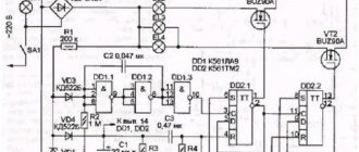
First of all, we check the supply voltage. We measure with a conventional multimeter, switched to constant voltage mode, on the electrolytic capacitor of filter C3. In relation to the common wire (minus the diode bridge and capacitors C3, C4, as is more convenient).
The voltage when the relays are turned off (almost no load, idle) on the filter capacitor is 11.2V; when any of the relays is turned on, it drops to 6V. At this voltage, even if the decoder gives a signal to open the transistor and it opens, the relay will still not turn on.
Naturally, suspicion immediately fell on the part of the electrical circuit responsible for power supply. Namely, to the limiting capacitor C2 in front of the diode bridge.
It says 155J. This means 15x10^5 picoFarads. And since there are a million picoFarads in 1 microFarad, this means that the capacitance of the capacitor is 1.5 μF. The voltage is clear, 250V.
If its capacitance has dropped, then it greatly limits the current of the diode bridge, and under load the voltage at the bridge output (and at the input, in the first place) drops significantly.
Another possible culprit for the drawdown is the electrolytic capacitor at the output of the diode bridge 470 uF 25V.
We change the 1.5 µF capacitor.
Now we measure the voltage at the output of the diode bridge in four operating modes:
- idle: 12.9V,
- switching on one relay: 12.2V,
- switching on two relays: 11.7V,
- switching on three relays: 10.5V.
Everything works fine!
Other malfunctions of chandelier controllers are below:
How to bind a remote control to a chandelier
In some remote control systems, it is necessary to bind the remote control to the lamp (synchronize). This procedure can be done with one remote control and several lamps in different rooms and control them using a single device (although you will have to carry the remote control with you all the time). You can try to attach your own remote control to each lamp in the room and control them independently. The procedure varies slightly among different manufacturers, but in general it is approximately the same:
- supply voltage to the chandelier from the wall switch;
- wait a few seconds, point the remote control at the lamp;
- press the button specially allocated for synchronization;
- After a few seconds, the lamp will respond in the form of one or more blinks and switch to glow mode.
Remote control with a binding button (Setup).
The button for primary synchronization is most often marked with a radio signal symbol, but not necessarily. This could be a button for one of the channels or just a button to turn on the light. Usually the entire setup procedure, indicating the buttons, is described in the instructions.
The controller we repair
Now the most interesting thing - I will describe the process of repairing the Kedsum K-PC803 controller , a photo of the appearance of which I already provided at the beginning of the article.
In the process of repairing this controller, like any transformerless electronics, you need to remember the danger - the circuit is always under mains voltage!
The circuit of this controller almost completely coincides with the circuit given above. The only difference is that this controller has not 2 channels, but 3. But the principle is absolutely the same. Let's take a little time to get acquainted with some of the internals and differences from the above diagram.
This is what a controller for controlling a 3-channel chandelier looks like from the inside:
Appearance of the controller circuit
A little closer:
Closer view of the controller circuit
Three relays (black, left) correspond to three control channels.
To the right of the top relay we see a row of black semicircular parts. These are three key transistors and a +5V stabilizer. Here's what it looks like from a different perspective:
Details on the controller PCB
In this photo you can distinguish transistors Q1, Q2, Q3 - key ones for turning on the relay (type - C9013), a + 5V stabilizer for powering the radio frequency part - L78L05, and a radio signal decoder chip HS153SP-J.
Reverse side of the circuit (soldering side). I signed the conclusions in the photo to make it easier to carry out reconnaissance:
Controller printed circuit board. View from the soldering side
Independent creation of remote control of a lighting device
Needless to say that today almost any chandelier can be equipped with a remote control? In this case, there is no need to search the Internet for some microcircuits, produce printed circuit boards, solder radio elements yourself, etc.
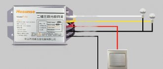
China provides everything you need ready-made. We are talking about a remote control unit. They differ mainly only in size and number of control channels. The most common models are:
In the case of a three-arm chandelier, it is better to opt for a three-channel control unit. It immediately shows a schematic diagram of how to connect to the lighting fixture.
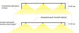
We recommend that you measure the lighting control unit in advance. After all, it should be located in such a way as to remain invisible. 2.5 cm thickness is the best option. As a rule, such blocks fit into any decorative mounting bowl of modern chandeliers.
If not repaired
If the repair has reached a dead end, and there are no resources (psychological, material and time) to continue it, then you can simply buy a controller.
I believe that these three controllers have the same hardware, with the exception of the number of relays with transistors, and the power of the internal power circuit.
Of course, it’s not possible to describe all the intricacies of circuit design and repair of radio-controlled chandelier controllers here, so ask questions in the comments, and we’ll figure it out together.