Full voltage standards in the electrical network: GOST
Despite the fact that the majority of ordinary people and people who do not belong to the category of knowledgeable in the field of voltage in their electrical network will affirmatively say that the standard voltage is 220 V. To their surprise, even despite the old and familiar stickers, on which indicates the generally accepted standard are no longer relevant.
Since 2015, a new standard has been in force in the Russian Federation - levels of 230 V and 400 V, which corresponds to European standards.
Such acts have also been adopted in Ukraine and the Baltic countries, including Belarus.
What did the change in standard lead to:
- The operating voltage on the power cable has changed;
- Fluctuations have become a little more significant than before, but still within the acceptable limits of 5% and the maximum – 10%;
- The potential payment for electricity supply services has not increased by a completely symbolic amount;
- Voltage supply frequency – 50 Hz.
Voltage standards in the electrical network depend on the type of purpose of the building
Thus, the network voltage should be considered slightly increased in everyday practice. But in reality, everything is different, and this promises the presence of pitfalls in the supply of electricity to organizations. Despite the generally accepted standard, organizations supplying voltage to apartments in houses supply everything according to the same standards adopted back in Soviet times and equal to 220 V. All this happens officially in accordance with GOST 32144-2013, which is what suppliers are guided by.
Selecting the rating of the circuit breaker
Applying the formula I = P/209, we find that with a load with a power of 1 kW, the current in a single-phase network will be 4.78 A. The voltage in our networks is not always exactly 220 V, so it would not be a big mistake to calculate the current strength with a small margin like 5 A for every kilowatt of load. It is immediately clear that it is not recommended to connect an iron with a power of 1.5 kW to an extension cord marked “5 A”, since the current will be one and a half times higher than the rated value. You can also immediately “graduate” the standard ratings of the machines and determine what load they are designed for:
- 6 A – 1.2 kW;
- 8 A – 1.6 kW;
- 10 A – 2 kW;
- 16 A – 3.2 kW;
- 20 A – 4 kW;
- 25 A – 5 kW;
- 32 A – 6.4 kW;
- 40 A – 8 kW;
- 50 A – 10 kW;
- 63 A – 12.6 kW;
- 80 A – 16 kW;
- 100 A – 20 kW.
Using the “5 amperes per kilowatt” technique, you can estimate the current strength that appears in the network when connecting household devices. You are interested in peak loads on the network, so for the calculation you should use the maximum power consumption, not the average. This information is contained in the product documentation. It is hardly worth calculating this indicator yourself by summing up the rated powers of the compressors, electric motors and heating elements included in the device, since there is also such an indicator as the efficiency factor, which will have to be assessed speculatively with the risk of making a big mistake.
When designing electrical wiring in an apartment or country house, the composition and passport data of the electrical equipment that will be connected are not always known for certain, but you can use the approximate data of electrical appliances common in our everyday life:
- electric sauna (12 kW) - 60 A;
- electric stove (10 kW) - 50 A;
- hob (8 kW) - 40 A;
- instantaneous electric water heater (6 kW) - 30 A;
- dishwasher (2.5 kW) - 12.5 A;
- washing machine (2.5 kW) - 12.5 A;
- Jacuzzi (2.5 kW) - 12.5 A;
- air conditioner (2.4 kW) - 12 A;
- Microwave oven (2.2 kW) - 11 A;
- storage electric water heater (2 kW) - 10 A;
- electric kettle (1.8 kW) - 9 A;
- iron (1.6 kW) - 8 A;
- solarium (1.5 kW) - 7.5 A;
- vacuum cleaner (1.4 kW) - 7 A;
- meat grinder (1.1 kW) - 5.5 A;
- toaster (1 kW) - 5 A;
- coffee maker (1 kW) - 5 A;
- hair dryer (1 kW) - 5 A;
- desktop computer (0.5 kW) - 2.5 A;
- refrigerator (0.4 kW) - 2 A.
Standard parameters of the electrical network
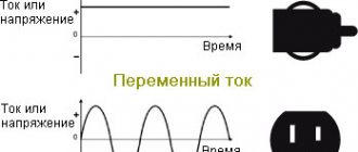
The norms of generally accepted standards also regulate the basic parameters inherent in electricity supplied to homes. Taking into account the fact that technical GOST consists of dozens and dozens of pages of complex terminology and calculations, a general assessment of the given categories will be given here. As is generally accepted, the main parameters that determine our household electricity are the frequency and strength of alternating current and voltage. However, there are a number of others that are worth considering.
Standard electrical network parameters include:
- Temporary stress factor;
- Pulse voltage;
- Voltage frequency deviation on the power cable;
- Voltage range;
- Duration of voltage loss and others.
All of the above indicators in one way or another influence the loss or excess of established energy supply standards in the network.
Contact options
Contact resistance
The Contact Resistance of a closed contact typically does not exceed 100 mOhm (milliohm).
Remember when we considered a field-effect transistor as an analogue of a relay?
So, the channel resistance of a powerful field-effect transistor can be orders of magnitude less - hundredths and thousandths of an Ohm.
The lower the resistance, the less the contact (or field-effect transistor channel) heats up.
Let us remind you that the relay contacts are coated with special alloys. In our case, this is an alloy of silver and tin oxide (AgSnO), which has a high melting point and resistance to welding and electrical erosion when switching high-current and inductive loads.
It should be noted that switching inductive loads (which is what happens in a UPS) is the most difficult mode for relay contacts. In this case, an electric arc may occur between them, which greatly reduces their service life.
The datasheet must specify the maximum current switched by the contacts (Contact Rating).
Response time
Operate Time is the time it takes for the relay to go from the “off” state to the “on” state. For different types of relays, this parameter ranges from approximately 1 to 200 milliseconds.
The response time is determined by the design of the mechanical part of the relay - the mass of the armature and the elasticity of its spring.
In our case, the response time does not exceed 10 ms.
Release time
The relay release time is the time during which it goes from the “on” state to the “off” state.
Please note: as a rule, the release time (except in special cases) is less than the operating time.
In our case, it is no more than 5 ms.
If you carefully examine the graphs given in the datasheet, you can see that the response time can be controlled to some extent by changing the voltage on the winding.
So, for a voltage of 75% of the rated voltage, the response time will be approximately 10 ms, at the rated voltage - about 5.5 ms, and at the maximum operating voltage - about 3.5 ms.
It is interesting to note that the release voltage remains almost unchanged.
Maximum voltage deviation in the electrical network
The current in the network is, for natural reasons, not constant and varies in certain parameters. Within the framework of the new 230 V/400 V standard, the nominal deviation is permissible within 5% and a maximum of no more than 10% should be observed in short-term intervals. Thus, such a theoretical deviation is allowed within 198 V and up to 242 V. This range can be considered relevant for most current apartments.
What affects network fluctuations in energy supply and voltage loss:
- One of the most common reasons is obsolescence of equipment, including meters, electrical panels, wiring cables, and so on;
- Significant errors are also observed in a poorly maintained network;
- Errors when planning and performing installation work in the house;
- Significant increase in energy consumption indicators exceeding the established standard.
As already noted, network fluctuations of +-5% are acceptable. So, for example, according to the supplied indicator of 220 volts, the permissible deviation in the network is equal to 209 V and the maximum excess is equal to 231 V.
Information about power line designs
According to their configuration, electrical networks are divided into closed and open. Examples of networks of various configurations are shown in Fig. 1.
Rice. 1. Examples of networks of various configurations : a – open network; b – simple closed network; c – complex network
An open network is a network that does not contain closed circuits (with the exception of circuits formed by different phases, as well as phase and zero). In such networks, consumers can receive power from only one side.
A network is called closed if it contains at least one circuit. In this case, some consumers receive power from two or more sides. These networks, in turn, are divided into simple closed ones, which contain only one circuit, and complex closed ones, containing two or more circuits.
Overhead lines include the following structural elements: wires, cables, supports, insulators and linear fittings.
Wires are designed to transmit electricity. They can be insulated (for overhead lines and overhead lines) and non-insulated.
Overhead cables are located at the top of the supports and serve to protect the line from direct lightning strikes.
Overhead line supports are designed to support wires and cables. Supports are divided into anchor, intermediate, straight and corner. There are also special types of supports: transitional, transposition and branch. The supports are made of wood (up to 110 kV), metal (35 kV and above) and reinforced concrete (up to 500 kV).
Insulators are designed for attaching wires to supports and for insulating wires from supports. Insulators are divided into pin (used up to 35 kV) and pendant (35 kV and above). Suspended insulators are assembled into garlands. The number of insulators in a garland depends on the voltage class and type of supports.
Linear fittings include clamps, coupling fittings, vibration dampers and damping loops, and spacers. Clamps are designed for fastening wires to insulators. Coupling fittings are used for hanging garlands on supports, for connecting multi-chain garlands to each other and for connecting wires and cables. Spacers are used to fix the split phase wires relative to each other.
The main types of overhead line supports are anchor and intermediate. The supports of these two main groups differ in the way the wires are suspended. The wires are suspended on intermediate supports using supporting garlands of insulators (Fig. 2). The distance between the intermediate supports is called the intermediate span, or simply the span, and the distance between the anchor supports is called the anchor span. Intermediate supports are installed on straight sections of overhead lines to support the wire in the anchor span. An intermediate support is cheaper and easier to manufacture than an anchor support, since due to the equal tension of the wires on both sides, it does not experience stress along the line if the wires are not broken. Intermediate supports make up 80...90% of the total number of supports.
Rice. 2. Diagram of the overhead line anchor span and the crossing span with the railway
Anchor supports are designed for rigidly securing wires at particularly critical points of overhead lines: at the intersections of engineering structures (for example, railways, 330...500 kV overhead lines, highways with a carriageway width of more than 15 m, etc.) and at the ends of overhead lines. Anchor supports on straight sections of the overhead line route, when hanging wires on both sides of the support in normal modes, perform the same functions as intermediate supports. But anchor supports are designed to withstand one-way tension along wires and cables when wires or cables break in the adjacent span. Anchor supports are much more complex and more expensive than intermediate ones, and therefore their number on each line should be minimal.
Corner supports are installed at the turning points of the line. The angle of rotation of the line is the angle α in the plan of the line (Fig. 3), supplemented to 180° to the internal angle β of the line. The traverses of the corner support are installed along the bisector of angle β.
Rice. 3. Angle of rotation of the overhead line : 1 – support footrests; 2 – traverse; 3 – loop
Corner supports can be of anchor and intermediate types. In addition to the loads taken up by the intermediate supports, the corner supports are also subject to loads from the transverse components of the tension of wires and cables. Most often, at line rotation angles of up to 20°, anchor-type corner supports are used.
On overhead lines, special supports of the following types are used: transpositional - to change the order of the wires on the supports; branch lines - for making branches from the main line; transitional - for crossing rivers, gorges, etc.
Transposition is used on lines with a voltage of 110 kV and above with a length of more than 100 km in order to make the capacitance and inductance of all three phases of the overhead line circuit the same. At the same time, on the supports, the relative position of the wires in relation to each other in different sections of the line is successively changed: the wire of each phase passes one third of the line length in one place, the second in the other, and the third in the third place. This triple movement of wires is called a transposition cycle (Fig. 4).
Rice. 4. Cycle of transposition of wires of a single-circuit line
The most common arrangements of wires and lightning protection cables on supports are shown in Fig. 5. The arrangement of wires in a triangle (Fig. 5, a) is used on overhead lines with a voltage of 10 kV and on single-circuit overhead lines with a voltage of 35...330 kV with metal and reinforced concrete supports. The horizontal arrangement of wires (Fig. 5, b) is used on overhead lines with a voltage of 35...220 kV with wooden supports and on overhead lines with a voltage of 330 kV. This arrangement of the wires allows the use of lower supports and reduces the likelihood of wires jamming when ice forms and wires dance. Therefore, a horizontal position is preferable in icy areas.
On double-circuit overhead lines, the arrangement of wires with a reverse tree is more convenient for installation conditions (Fig. 5, c), but it increases the mass of the supports and requires the suspension of two protective cables. The most economical are double-circuit overhead lines with a voltage of 35...330 kV on steel and reinforced concrete supports with wires arranged in a barrel (Fig. 5, d).
Wooden supports are used on overhead lines with voltages up to 35 kV inclusive. The advantages of these supports are their low cost (in areas with forest resources) and ease of manufacture. The disadvantage is that the wood is susceptible to rotting, especially at the point of contact with the soil. An effective remedy against rotting is impregnation with special antiseptics.
Rice. 5. Location of wires and cables on supports : a – along the vertices of the triangle; b – horizontal; c – reverse tree; g – barrel
Metal (steel) supports used on power lines with voltages of 35 kV and above require painting to protect them from corrosion during operation. Install metal supports on reinforced concrete foundations. These supports, according to their design, can be classified into two main schemes - portal (Fig. 6, a, b) and tower or single-column (Fig. 6, c, d), and according to the method of fastening to the foundations - to free-standing supports (Fig. 6, d) and supports on guy wires (Fig. 6, a–c).
Regardless of the design solution and layout, metal supports are made in the form of spatial lattice structures. Anchor supports differ from intermediate ones in the increased reach of the traverses and the reinforced design of the support body. On overhead lines with a voltage of 500 kV, as a rule, a horizontal arrangement of wires is used. Intermediate supports with a voltage of 500 kV can be free-standing portal or guyed. The most common design of a 500 kV support is a guyed portal (Fig. 6, a). For a 750 kV line, both portal supports with guys and V-shaped supports of the “Nabla” type with split guys are used. The main type of intermediate supports for 1150 kV lines are V-shaped supports on guys with horizontal wires (Fig. 6, b).
Rice. 6. Metal supports : a – intermediate single-circuit on guys with a voltage of 500 kV; b – intermediate V-shaped with voltage 1150 kV; c – intermediate support of a direct current overhead line with a voltage of 1500 kV; g – free-standing with voltage 110 kV
The most secure type of power transmission, but also expensive, is cable power transmission.
Cable lines are laid in earthen trenches, special cable structures, on overpasses, in galleries, openly along the walls of buildings and structures, in pipes, in the internal workshop premises of industrial enterprises, as well as collectors - underground structures intended for laying cables in them together with communication lines and other communications.
Each type of special structure for laying cables is characterized by the maximum number of power cables that can be laid in it. Trench – 6 cables, channel – 24, block – 20, tunnel – 72, overpass – 24, gallery – 56.
Rarely is preference given to any one type of cable routing. Usually mixed laying is used when, depending on specific conditions, a combined execution of various methods of laying cable lines is advisable.
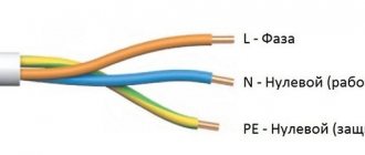
Cables, depending on the voltage level and purpose, have different designs. In 220/380 V circuits, which are mainly used in three-phase systems with a grounded neutral, the cables are manufactured mainly in a four-core design (three phase conductors and one neutral for connection to a grounded neutral - Fig. 7), although three-core cables are also produced. Plastics mainly based on polyvinyl chloride (PVC) plastics are used as electrical insulation of cores and protective sheaths of cables. The shape of the current-carrying cores is most often sectoral, since it makes it possible to obtain a compact and, accordingly, economical cable design. However, power cables of this type are also available with round cores. The core material is copper.
Rice. 7. Example of a typical cable design with voltage up to 1 kV
Medium voltage power cables are used in distribution networks with an insulated neutral for voltages of 6, 10, 20 and 35 kV. The main voltage of distribution networks of power systems in Russia and the CIS countries is 10 kV. Impregnated paper and plastic insulation are used as electrical insulation for medium voltage cables. Power cables with impregnated paper insulation for voltages of 6 and 10 kV are manufactured as three-core cables. Paper impregnated with oil rosin composition is used as phase and belt insulation. Such cables are produced with sector-shaped copper and aluminum conductors. To protect the hygroscopic insulation, the cable design includes a metal sheath made of lead or aluminum. Protective covers are applied over the metal shells for mechanical and corrosion protection.
High voltage power cables. This class includes cables for voltages of 110, (150), 220, (380) and 500 kV in relation to the rated voltages of power transmission systems adopted in Russia and the CIS countries. Voltages of 150 and 380 kV are used in some cases.
The electrical insulation of high voltage cables is subject to high requirements in terms of electrical strength and high reliability over long service lives (35 years or more). The electric field strengths in the insulation of such cables range from 7 to 15 kV/mm, i.e. they are the highest compared to the field strengths in any electrical apparatus and devices. Electric field strength is one of the main parameters that ensure acceptable design dimensions (diameters) of cables. High operating electric field strengths pose serious scientific and technical problems from the point of view of ensuring a long service life of cables. These problems have been successfully solved for two types of electrical cable insulation: paper-impregnated, operating under excess oil pressure (oil-filled cables - OLC), and cross-linked polyethylene (PE) using appropriate technologies that ensure the purity and required quality of insulation.
In the designs and manufacturing technology of MNCs, measures have been taken to ensure reliable insulation operation at high electric field strengths:
- The cable insulation during operation is under constant overpressure of insulating oil to prevent partial discharges in the insulation structure;
- The cable manufacturing technology provides for thorough thermal vacuum treatment of the insulation and oil to ensure minimal dielectric losses in the insulation, which determine the long service life of the cable.
In Fig. Figure 8 shows the design of a high-pressure MNC in a steel pipe.
High voltage cables with cross-linked PE insulation have a number of important advantages in operation compared to MNC:
- do not require oil replenishment systems and pressure alarms, which reduces the labor intensity of maintenance and capital costs for the construction of cable lines;
- allow for laying without limiting level differences on the route;
- reduce the labor intensity of installation work when constructing cable lines;
- environmentally friendly (there is no oil leakage into the ground, which is observed during the operation of small oil pumps);
- have increased load capacity and resistance to short-circuit currents due to the higher heat resistance of cross-linked PE insulation compared to impregnated paper.
Rice. 8. Design of an oil-filled high-pressure cable in a steel pipe : 1 – paper insulation impregnated with oil; 2 – steel pipe; 3 – screen made of copper tape; 4 – copper sliding wire; 5 – conductive core; 6 – anti-corrosion coating
Rice. 9. Design of a high voltage cable with cross-linked PE insulation : 1 – conductor; 2 – screen along the current-carrying core; 3 – insulation; 4 – insulation screen; 5, 7 – water-swelling tapes; 6 – wire screen; 8 – load shell
The electric field strength in plastic insulation is at the same level as in impregnated paper insulation and ranges from 6 to 15 kV/mm, depending on the rated voltage of the cables. A typical design of a high voltage cable with XLPE insulation is shown in Fig. 9.
Voltage drop in the home network
The so-called voltage drop can be fraught with many undesirable consequences. Moreover, it is undesirable both by the residents themselves and by the supplier organization, because it will be the one who will cover all unforeseen expenses. For objective reasons described earlier, power outages can reach record levels.
If such fluctuations are detected, the maximum drawdown is recorded and with these indicators, referring to the generally accepted standard and quality of the supplied energy, you need to contact the electricity supply authorities.
If there is no desire to correct the defects, this is grounds for filing a claim in court.
What are the consequences of exceeding or significantly reducing the established norms for voltage supply in the house:
- Light bulbs burn out faster;
- This is especially harmful for a refrigerator, washing machine and other electrical household appliances that require powerful and constant voltage;
- The service life of any electrical equipment, including microwaves, toasters, TVs, computers, and so on.
Thus, it becomes obvious that all classes of electrical engineering suffer from severe voltage fluctuations. This influence is especially destructive if the network voltage is low. And the obligation to provide uninterrupted, stable and high-quality current belongs to the organization that supplies it and, according to the contract, must ensure its high-quality service.
Determining whether there is a deviation from the norm is quite simple.
When the voltage is low, electrical appliances will stop turning on or will work intermittently. With increased voltage, devices can completely fail and “burn out”. If the voltage in the apartment exceeds or falls short of the specified maximum standards, the owner has the right to contact the management company. Procedure:
- The owner makes a complaint to the company servicing the house.
- The electrician measures the voltage, draws up a report of work performed, and records deviations from the norm.
- The owner submits an act to the management company to eliminate the causes of deviations from the norm.
- If the management company refuses to correct the situation, the owner has the right to go to court.
Amount of permissible voltage drop: PUE
According to the accepted rules for the design of electrical installations (PUE) back in the former USSR, a voltage drop is the difference in voltage levels at different points of the network. As a rule, these are the starting and ending points of the chain. In established standards, the law requires a distinction between the concepts of voltage deviation and voltage loss. If the first case, on a generally accepted scale, is considered using the example of an incandescent lamp, the deviation indicator of which is recognized as nominal and mandatory, then in the case of the loss considered on the station buses, this is recognized as a recommended indicator.
Normal voltage drop in the network:
- In so-called overhead lines – up to 8%;
- In cable power supply lines – up to 6%;
- In networks of 220 V - 380 V - in the region of 4-6%.
In this case, a drop in the emergency mode is considered to be a drop of up to 12% in the network - this is the established limit. A fall above the established norm promises the activation of the automatic protective system, which should be activated when the lower norm is reached for at least 30 seconds.
Also in some sources you can find voltage standards that exceed even the new indicators of 230 V and 400 V. Do not confuse examples of domestic use with a plant or factory, where the indicators naturally significantly exceed the domestic environment.
Calculation of power by current and voltage
This calculation occurs based on the actual power; it must be done before you start designing your home (house, apartment).
- This value determines the cables that power the devices that are connected to the electrical network.
- Using the formula, you can calculate the current strength; for this you need to take the exact network voltage and the load of the powered devices. Its size gives us an idea of the cross-sectional area of the veins.
If you know all the electrical appliances that should be powered from the network in the future, then you can easily make calculations for the power supply diagram. The same calculations can be performed for production purposes.
Single-phase 220 volt network
Current formula I (A - amperes):
Where P is the electrical full load (its designation must be indicated in the technical data sheet of this device), W - watt;
U—mains voltage, V (volts).
The table shows the standard loads of electrical appliances and the current they consume (220 V).
| electrical appliance | Power consumption, W | Current strength, A |
| Washing machine | 2000 – 2500 | 9,0 – 11,4 |
| Jacuzzi | 2000 – 2500 | 9,0 – 11,4 |
| Electric floor heating | 800 – 1400 | 3,6 – 6,4 |
| Stationary electric stove | 4500 – 8500 | 20,5 – 38,6 |
| microwave | 900 – 1300 | 4,1 – 5,9 |
| Dishwasher | 2000 — 2500 | 9,0 – 11,4 |
| Freezers, refrigerators | 140 — 300 | 0,6 – 1,4 |
| Electric meat grinder | 1100 — 1200 | 5,0 — 5,5 |
| Electric kettle | 1850 – 2000 | 8,4 – 9,0 |
| Electric coffee maker | 6з0 — 1200 | 3,0 – 5,5 |
| Juicer | 240 — 360 | 1,1 – 1,6 |
| Toaster | 640 — 1100 | 2,9 — 5,0 |
| Mixer | 250 — 400 | 1,1 – 1,8 |
| Hairdryer | 400 — 1600 | 1,8 – 7,3 |
| Iron | 900 — 1700 | 4,1 – 7,7 |
| Vacuum cleaner | 680 — 1400 | 3,1 – 6,4 |
| Fan | 250 — 400 | 1,0 – 1,8 |
| TV | 125 — 180 | 0,6 – 0,8 |
| Radio equipment | 70 — 100 | 0,3 – 0,5 |
| Lighting devices | 20 — 100 | 0,1 – 0,4 |
Mandatory voltage regulation in electrical networks
Carrying out your own voltage regulation is not only labor-intensive, but also requires financial investment. An even more difficult option is to seek stabilization of the current in the network from the supplier organization. This can be done by filing complaints, personal appeals, and lawsuits, however, the result is not always achieved even by these methods.
If you still decide to correct the picture yourself, then this is possible in the following way:
- Method of centralized voltage regulation. This approach involves calculating how many changes will be needed to stabilize the situation and adjusting the central power supply accordingly.
- Linear impact method. This is done using a so-called linear regulator, which changes the phases using a secondary winding on the circuit.
- Use of capacitor banks in the network. This method is theoretically called reactive power compensation.
- Also, an extremely unstable network can be corrected using longitudinal compensation. It involves connecting capacitors in series to the network.
Another relevant option, if the deviation from the established norm is not too pronounced, is to install one large or several small stabilizers in the network. This will require some financial investments, special installation skills, and is also not suitable for highly fluctuating power supply systems, because they simply cannot do a large amount of work and regulate a large amount of voltage.
So, as has already been determined, the new generally accepted standard is the network voltage in an apartment from 230 V to 400 V. For example, the voltage scale can be 240 V, 250 V, taking into account the maximum permissible error. However, for the e1f outlet we are used to, the operating voltage is still the same 220V level, which has been familiar to us all since the Soviet period.
Star and Delta circuits in a three-phase network
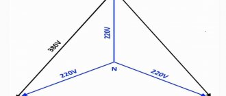
There are various variations for connecting a load with an operating voltage of 220 and 380 Volts to a three-phase network. These patterns are called “Star” and “Triangle”.
When the load is designed for a voltage of 220V, it is connected to a three-phase network according to the “Star” circuit , that is, to phase voltage. In this case, all load groups are distributed so that the powers in the phases are approximately equal. The zeros of all groups are connected together and connected to the neutral wire of the three-phase input.
All our apartments and houses with single-phase input are connected to Zvezda; another example is the connection of heating elements in powerful heaters and convection ovens.
When the load has a voltage of 380V, it is switched on according to the “Triangle” circuit, that is, to linear voltage. This phase distribution is most typical for electric motors and other loads where all three parts of the load belong to a single device.