Purchase
You can buy a wire with the most favorable conditions by contacting our company. We work with trusted manufacturers and do not use the services of intermediaries, which allows us to reduce the cost of cable and wire products to a minimum. Placing an order is done in the fastest and most convenient way - through the website or by email. After receiving your questionnaire, we immediately begin to formulate the terms of purchase.
We work with individuals and legal entities, engaged in wholesale and retail trade. Complete with the product, the customer receives a certificate of conformity and a quality certificate. If necessary, our consultants will answer all your questions. You can buy products from the assortment available in the warehouse or from the manufacturer to order. The price of SIP-3 wire depends on the delivery conditions and order volume. For regular customers, we have provided a system of discounts and special offers.
How to stretch a cable line
If it so happens that this wire sagged in your area of responsibility (a branch from the main highway to your property) and the balance demarcation points are written in the agreement for the supply of electricity, then the overhead line in this area is completely your business.
This procedure is carried out with all insulators, along the tensioned line to the extreme support. After tensioning, the taps are connected and, after making sure that the line is ready and safe, they submit an application to supply voltage.
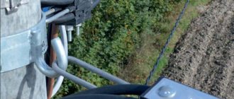
Stretching the SIP wire occurs similarly to the method described above, with the only difference that instead of insulators, special fastening fittings and anchors are used, as shown in the photo below:
What kind of lighting do you prefer?
Built-in Chandelier
Note! The wires are tensioned with a slight sag, about half a meter, to compensate for temperature changes in summer and winter.
To tension power lines, self-supporting insulated wires or cable wiring, both restored and newly laid, hand winches, ratchets or “frogs” are used, stretching the cable between spans or supports, in the area to the house or garage. Fixing in a tense state to anchors and fastening fittings. The video below clearly shows how to string a wire from a pole to a house:
And in this video you can watch the technology of tensioning a wire with a manual winch:
That's all we wanted to tell you about how to stretch a wire from a pole to a house and where to call if you find that the cable between buildings or supports is sagging. As you can see, cable line tensioning should be trusted to specialists who, with the help of devices, can quickly and, most importantly, safely complete all the work!
Application
The cable is used when installing overhead power lines. The cable transmits and distributes electrical energy between consumers; the alternating current parameters in the network must correspond to the characteristics of 20 kV (35 kV maximum), 50 Hz. Laying is carried out in areas with temperate, cold and tropical climates in industrial and marine areas (sea coast, shore of a salt lake, areas with saline sand).
The conductor is used when constructing sections of routes, branches and taps in compliance with the rules of voltage distribution. The self-supporting wire SIP-3 can be installed in urban areas, rural areas, and uninhabited areas where it is necessary to lay long-distance mains with minimal voltage losses. Thanks to the possibility of installation on supports installed at a large distance from each other, the cable is laid over historical and architectural monuments. This does not disrupt the overall composition.
The wire is applicable only for connecting the first category of consumers. Due to the possibility of selecting the required cross-section, a reduction in material costs for the construction of additional substations is achieved.
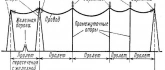
Cable installation on poles
Overhead power lines with SIP wires are called VLI. Their installation traditionally begins with clearing the area of trees, bushes, and other possible obstacles that interfere with rolling out and tensioning the wires on the supports.
When building a new power line, it is more convenient to attach the brackets for the wire to the pole on the ground before installing it. The brackets are fastened to the supports using a clamp made of corrosion-resistant steel tape. After tightening, excess tape is removed.
The poles with mounting brackets are installed and the installation of overhead power lines begins. Installation of SIP on supports takes place using components at an outside air temperature of at least 20 o C. The technology for installing SIP has its own peculiarity associated with rolling out the wire. It protects the insulation from damage. The wire is rolled out from a drum installed on the machine. SIPs are distributed on the supports using rollers and a tension rope - leader.
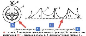
Manual wire rolling
The technology for unwinding from a SIP coil involves manual execution of the process, provided that the area is limited to one hundred meters and the cross-section of the phase conductors does not exceed 50 square meters. mm. Manual rolling of wires is allowed in populated areas where the span length does not exceed 50 m. Manual rolling technology has the following sequence:
- A drum with wire is installed near the first anchor support, where the power line will begin. Its distance to the pillar should be no less than the height of the support itself. The rope is attached to the end of the SIP with a mounting stocking.
- Rollers are installed on each intermediate post, while the rope is laid in them. Under the supervision of an electrician, the wire is pulled along the supports. Laying occurs smoothly without jerking with simultaneous rotation of the drum and tension of the rope. The maximum speed of manual rolling should not exceed 5 km/h, while preventing the SIP from touching the ground and any building structures.
- On the last pole of the power line, the neutral core is fixed with a clamp to the anchor bracket. A free protrusion of the cores is left behind the bracket for further connection.
- After laying out the wires on the supports, their tension begins. A winch with a measuring device - a dynamometer - is fixed to the first post. The tension is carried out with a certain force, displayed by a dynamometer. The tension force is determined from the tables, while simultaneously inspecting the quality of the wire tension between the posts. After tensioning the entire power line, the insulated wire is left to hang for a while.
- Further installation on the first post involves attaching a clamp to the bracket and fixing the zero core in it. The wiring harness is tightened with clamps, the winch and transport roller are removed. The SIP is cut off from the coil, leaving the ends of the required length.
- On the intermediate post, the wires are transferred from the roller to the clamp. Plastic wedges are used to separate the carrier core from the phase wires, while simultaneously securing it with clamps in the clamp. After removing the unrolling roller, all the cores are tightened with clamps at a distance of 150 mm from the clamp on both sides. An intermediate clamp is used to tighten and secure the phase conductors under the clamp.
At this stage, the installation of SIP in one span is completed. The following spans are mounted using a similar method.
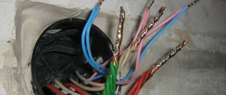
Cable connection
Having laid the self-supporting wire on the supports, you need to connect it to the main power line and lead from it to the house:
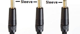
- The cable is connected to the mains power supply using hermetically sealed clamps that ensure good contact. The connection involves stripping the insulation from the wire, after which a clamp is placed on its end. The edge of the clamp is covered with a press, squeezing it until the two parts of the matrix are closed. The end of the other wire being connected is secured in a similar way. You can connect SIPs to bare main wires using these clamps or sleeves for bare wires. In the second case, the sleeves must be supplemented with materials for sealing.
- To connect the building input to the main line from bare wires, branch clamps are used. Typically, SIPs without a neutral wire are used for branches. Then the conductors of the same cross-section of one phase are secured in one clamp with the entire bundle.
- You can connect the house input without removing the insulation from the main wire using a piercing clamp. As the bolts are tightened, the teeth of the clamp pierce the wire insulation, making contact with the aluminum core. The tightening force of the bolts is determined by the breaking of the calibration head.
Calculation of boom sag and tension force of SIP
In this article I would like to provide a method for calculating the sag of self-supporting insulated wires of the SIP-2A type. Using this method, you can calculate the sag of a SIP for a span length different from the standard value. Do you want to make a span of more than 40m?
This technique, in principle, can be applied to SIP-1, SIP-1A and SIP-2.
SIP-1 differs from SIP-2 in the insulation of the cores. SIP-1 uses light-stabilized thermoplastic polyethylene (PE), and SIP-2 uses light-stabilized cross-linked PE. The letter “A” indicates that the zero-carrying core is insulated. In terms of characteristics, SIP-2 is better than SIP-1; it passes more current and has a slightly smaller mass.
The purpose of this calculation is to determine the tension force of the supporting wire at a given installation temperature, as well as to determine the sag of the SIP.
Calculation of SIP sag
Let us determine the tension force T(daN) depending on the ambient temperature during installation.
1 First you need to calculate the equivalent span length ae (m) using the formula below
Equivalent span length
2 Using the table, we determine the parameter P depending on the equivalent span length ae and the cross-section of the wire.
design , mm²
| Parameter P at 40°C without wind, m | Recommended maximum span length, m | |||||
| Span length (normal wind load) | Span length (high wind load) | |||||
| 30m | 45m | 60m | 30m | 60m | ||
| 3×35+54,6 | 300 | 350 | 400 | 300 | 350 | 60 |
| 3×50+54,6 | 250 | 300 | 350 | 250 | 300 | |
| 3×70+54,6 | 200 | 250 | 300 | 200 | 250 | |
| 3×70+70 | 250 | 300 | 350 | 250 | 300 | |
| 3×150+70 | 200 | 250 | 250 | 200 | 250 | |
3 Based on the obtained value P, the equivalent span length ae and the given ambient temperature during installation, we determine the tension force T according to the table.
Determination of tension force T (daN)
Calculation of the sag value of the SIP wire.
The sag of a self-supporting insulated wire is determined by the following formula:
where a is the span length;
p — linear weight (daN/m);
T - mechanical tension (daN).
The linear weight of the SIP wire can be taken from the table below or from the manufacturer’s catalog.
| Type of SIP | (daN/m) |
| 3×35+54,6 | 0,610 |
| 3×35+54.6+2EP | 0,739 |
| 3×50+54,6 | 0,732 |
| 3×50+54.6+2EP | 0,860 |
| 3×70+54,6 | 0,936 |
| 3×70+54.6+2EP | 1,06 |
| 3×70+70 | 0,967 |
| 3×70+70+2EP | 1,09 |
| 3×150+70 | 1,66 |
| 3×150+70+2EP | 1,79 |
Note: EP - lighting wires.
Under the influence of temperature, the metal either expands or contracts, which is why the tension of the wire T changes. If you need to calculate the maximum sag of the SIP, then for the calculation you need to take the largest span and select the T parameter based on the temperature of +40 degrees.
It turns out that the overhead line (VLI) must be designed in such a way that the load on the neutral wire does not exceed the established values.
The only thing that confuses this calculation is that it is not entirely clear how the thickness of the ice wall was taken into account. After all, when the wires become iced, their weight increases, and accordingly the sag and mechanical tension increase. In my opinion, in the table for determining the force T at a temperature of -5 degrees, ice and snow accumulation are taken into account.
Rules for entering the house
After the SIP cable has been connected from the overhead line to the wall of the house, the owner is faced with the question of how to properly bring it into the house? Is it permissible to do this using a SIP cable, or should it be a copper cable that must be brought inside the house, having first connected it to the main trunk wire? To give the correct answer to this question, you must first familiarize yourself with a number of regulatory documents. First of all, you need to refer to the PUE, where there is no indication that the SIP cable can be installed inside residential premises.
Another document GOST R 52373−205 states that SIP cable can be used exclusively for laying overhead lines. Although, if you carefully read clause 10.3 of this GOST, then the SIP cable can be laid along the wall of the building, but this must be done while observing the following requirement - laying the wire on combustible bases should only be done in a corrugated or cable channel.
Cable entry
Based on the above, it becomes clear how exactly it is necessary to introduce an electrical cable into the house. The first step is to install a sealable box on the facade of the house. It must be outdoor rated and have a protection level of at least IP65. We already install a circuit breaker in it - two or four poles - it all depends on the voltage (220 or 380 V). We connect a SIP cable to the machine, and from the machine we lead a cable that meets the requirements into the building.
For example, this could be a VVGng wire with a cross section of 10 mm2. The place where the cable enters the house must be reinforced with a plastic or steel pipe. For the machine, try to set the rated current to a level higher than the current of the machine, which is installed in your electrical panel.
Incorrect installation option
Another option is also possible - the cable is inserted into the building directly without installing a box with a circuit breaker on the facade of the house. This option is quite acceptable, even though it will be somewhat contrary to the rules. Many electricians and companies resort to this method. Controlling organizations are also not against it; they accept this installation option without any comments. Although, if you still want to protect yourself from possible problems, we advise you to choose the first input option.
Allowable distance
To ensure that no problems arise after connecting the house to the main power line, this must be done in compliance with certain rules. A SIP cable that was introduced into a house without taking them into account may one day lead to a fire and even electric shock to a person. If we turn to the requirements of the PUE, they list the following distances that must be observed when introducing a self-supporting insulated cable into a house:
- The branch support should be located no further than 10 m from the facade of the building.
- The overhead line support should be installed no further than 25 m from the facade of the building.
- The overhead line support should be located no further than 15 m before the branch support.
- The laid cables should sag in the overhead line span by no more than 6 m.
- Installation of cables on the facade of a building is permitted at a height of at least 2.7 m.
No tags for this post.
Permissible span of self-supporting insulated wire SIP-4.
Equipment for excavation of mine workings, POS, standard control, KR, AR
Well, if on a rope, then why not? Or maybe even the SIP itself will withstand the gravity. You need to calculate the tension. I'm lazy.
In general, the spans between the supports of 110 kV power lines are exactly 80-100 m. Between the supports of 6 kV power lines, our electricians made 30-50 m.
18.10.2010, 15:00
Design of substation and overhead lines
| #3 |
| or tell me the standard series where there is such a calculation or tabular data on SIP |
Code 24.0067 “Calculation spans for single-circuit and multi-circuit reinforced concrete supports of overhead line 0.38 with self-supporting insulated wires”
But there is no figure for more than 43m; everything is limited by the sag, the ice wall, and the wind.
19.10.2010, 09:08
Very relevant. For SIP4, it is not clear what diameter values to take, how to calculate the tension during ice (for a round wire everything is more or less clear, where the diameter of the wire is taken to it plus the thickness of the ice wall). And the standard series is not clear for which area downwind it was made, there are signs for different areas for ice, but it’s unclear downwind.
And how should you check the supports for mechanical strength? There are a lot of questions, but there’s no one nearby to ask.
design of hazardous production facilities and chemical productions
When calculating ice conditions, I take the maximum size of the wire cross-section, and the tension on the load-bearing cross-sectional area is calculated.
Supports for mechanical strength are considered as ordinary building structures - the body of the support itself (depending on the material of the support) plus the stability of fixing the support in the ground (this is really not the mechanical strength of the support)
And what value of d do you enter in this formula (formula for calculating the tension during ice on a wire)
. And thanks for the response
The manufacturer indicates the calculated outer diameter, should this be used in the calculations?