The inevitable material and financial losses that result from the failure of a cable line (CL) force us to look for the most effective ways to eliminate damage that minimize these losses. The correct choice of method and equipment for searching for damage sites determines the effectiveness of solving the problem, i.e. the maximum probability of correctly identifying the location of the damage and the minimum time spent on this. The causes of defects in cables are very diverse. The main ones are: mechanical or corrosion damage, manufacturing defects, defects in the installation of connecting and end couplings, drying out of the insulation due to local overheating of the cable and aging of the insulation.
Types of damage and basic search methods
| Types of damage | Damage diagram | Transition resistance, Ohm | Remote method | Topographic method | Equipment for identifying damage locations |
| Phase short circuit to cable sheath | Rп | Pulse | Acoustic | REIS-105M1, GP-24 “Acoustic”, PA-1000A | |
| 100 4 | Mostovoy | Acoustic, overhead frame | REIS-305, SC40, PKM-105, GP-24 “Acoustic”, PA-1000A | ||
| Rп ≤ 50 | Pulse | Acoustic, induction, overhead frame | REIS-105M1, KP-500K | ||
| 100 4 | Loop (bridge) | Acoustic | REIS-305, SC40, PKM-105, GP-24 “Acoustic”, PA-1000A | ||
| Rп ≤ 50 | Pulse | Acoustic | REIS-105M1, KP-500K | ||
| 100 4 | Mostovoy | Acoustic, induction | REIS-305, SC40, PKM-105, GP-24 “Acoustic”, PA-1000A | ||
| Short circuits between phases | Rп | Pulse | Induction | REIS-105M1, KP-500K | |
| Broken wire with grounding and without grounding | Rп > 106 | Pulse, oscillatory discharge | Acoustic, induction, overhead frame | REIS-305, SC40, SDC50, SD80, AIP-70, GP-24 “Acoustic”, PA-1000A, KP-500K | |
| Rп > 106 | Pulse, oscillatory discharge | Acoustic | REIS-305, SC40, SDC50, SD80, AIP-70, GP-24 “Acoustic”, PA-1000A | ||
| 0 Rп 3 | Pulse | Acoustic, induction | REIS-105M1, GP-24 “Acoustic”, PA-1000A, KP-500K | ||
| Floating breakdown | Rп > 106 | Oscillatory discharge | Acoustic | REIS-305, SC40, SD80, AIP-70, GP-24 “Acoustic”, PA-1000A |
Causes
A similar situation can arise not only in the conditions of direct operation, but also at the stage of installation work. In the process, workers can easily damage several lines, a manufacturing defect can be identified, work can be done on other communications that are not related to the target network, and many more sad scenarios that will lead to the line being inoperable.
In home electrical networks, wiring neatly hidden under favorite repairs can fail at the most inopportune moment. The most common reasons are manufacturing defects and microdamages caused to the wire during the installation process.
Whatever the reason, the challenge is to accurately determine the location of the rupture without ruining expensive repairs or digging up hundreds of meters of earth. We will consider this issue and existing methods for solving the problem.
Distance (relative) methods
- The pulse method is that electrical pulses (probing pulses) are sent into the cable line, which, propagating along the line, are partially reflected from the inhomogeneities of the wave impedance and return to the place from which they were sent. Using the time it takes for the pulse to travel to the inhomogeneity and back, which is proportional to the distance to it, the distance is calculated. You can determine the distance to the place of damage, wire breakage, cable length. You can determine the distances to inhomogeneities, couplings, single-phase and interphase cable damage.
- The capacitive method
can be used when cable cores are broken. The distance to the break point is determined by the value of the measured capacitance of the cable conductors. The measurement is carried out using AC bridges. AC bridges can be used to measure capacitance during breaks with an insulation resistance at the point of damage of at least 300 Ohms. At lower resistances, the measurement accuracy drops below the permissible value. - The oscillatory discharge method
is used to determine the distance to places of single-phase faults with a transition resistance at the fault site of the order of 10-100 kilo-ohms. Using a high-voltage testing machine, the voltage on the damaged cable core is raised to the point of breakdown. A short circuit in a charged cable core results in the appearance of electromagnetic waves that propagate from the point of breakdown at the defect site to the beginning and end of the cable line. By analyzing the voltage diagrams of the oscillatory process, you can calculate the distance to the defect. - The wave method
is used if the resistance at the damage site is from zero to hundreds of kilo-ohms. The method is implemented as follows. When the spark gap of a high-voltage rectifier installation breaks down, a high-voltage electromagnetic wave from a charged capacitor is sent into the line, which creates a breakdown at the site of damage to the cable line, which causes a wave oscillatory process in the capacitor-line circuit. When an electromagnetic wave sent from a capacitor reaches the place of damage, a breakdown will occur if the resistance at the place of damage is not zero Ohm, after which the wave front reflected from the damage will return to the place of sending - the capacitor, will be reflected from it and return to the place of damage. If the resistance at the damage site is close to zero, the discharge will not occur and the wave will be reflected from the short circuit. This process will continue until the wave dies out. By measuring the time dependence of the voltage at the cable terminals during the oscillatory process, it is possible to establish the time during which the wave reaches the breakdown site and calculate the distance to it. - The loop method
is based on measuring the current resistance of the cable cores (usually using a bridge). Used to determine the location of damage to protective plastic insulation. The accuracy of determining the distance to the damage site is low and amounts to about 15% of the measured length.
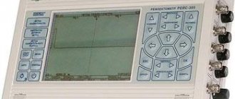
How to work with a tester
In order to use the multimeter, you need to remember the switch positions on the front panel. To search for a break, you will need resistance measurement or continuity testing modes (see figure).
Let's consider an example when the lighting in one of the rooms went out. There can be three types of faults:
- the switch has failed;
- the contact has disappeared at the place where the wires are connected to the switch;
- The conductor hidden in the gate broke.
All of them can be checked with a multimeter. In this case, it is necessary to follow the sequence of actions.
- It is necessary to de-energize the wiring in the apartment by turning off the circuit breakers in the electrical panel.
- How to check the switch? Having disconnected the wires from it, we check the resistance between its terminals. In one position of the switch the display should show 1 (open), and in the other - 0 (short circuit). If so, it means the switch is working. If there is a break in both positions, a new one is installed.
- We check whether there is voltage in the cable cores that supplies electricity to the junction box. Before checking, you need to put crocodiles on the ends of the probes, select the alternating voltage (ACV) measurement mode with a range above 200 V.
- Carefully connect the probes to the conductors one at a time. In order not to provoke a short circuit and not to suffer from electricity yourself, the ends of the wires should be placed as far from each other as possible.
- Electricity is reconnected to the wires. If a value greater than 200 appears on the display, it means the wiring is OK. If 0, you will have to look for an open circuit in the circuit going from the electrical panel to the distribution box.
All that remains is to check the hidden cable running from the junction box to the switch. How to find a broken wire in a wall?
- The electricity goes out.
- The tester operating mode switches to dialing.
- One of the probes is connected with a crocodile to one end of the cable core. Another probe goes to another cable core.
- In the distribution box, both wires being tested are connected, forming a closed circuit.
- If the cable is not broken, a sound signal will sound. If there is no signal, one of the wires is broken.
Topographic (absolute) methods
- The acoustic search method
is based on listening above the damage site to sound vibrations that arise at the damage site at the moment of a spark discharge from electrical impulses sent into the cable line. - A potential search method
is based on fixing on the ground surface along the path of electrical potentials created by currents flowing through the CL shell in the ground. - The induction search method
is based on monitoring the magnetic field around the cable, which is created by the current flowing through it from a specialized generator. By assessing the level of the magnetic field, the presence of CL and the depth of its occurrence are determined, and the location of the damage is determined by the nature of the change and the level of the field. This method is used to directly find places of damage on the cable in the event of a breakdown of insulation between the cores or to the ground, a break with a simultaneous breakdown of the insulation between the cores or to the ground, to determine the cable route and its depth, to determine the location of the couplings.
Briefly about cable line repair
Repair work on cable lines is usually classified into planned and emergency. As for the volume of such work, for the former it is, as a rule, capital, for the latter it is current.
During major works, planned replacement of cable lines, laying of new routes, etc. are carried out. If necessary, repairs and/or upgrades of related equipment are also performed. The latter include ventilation systems and lighting for cable tunnels, as well as pumps for pumping out groundwater. Considering the specifics of planned work, localization of defective areas is not required during their implementation.
The situation is completely different during emergency repairs. In order not to dig up the entire route, you should accurately determine the location of the wire break, insulation breakdown, etc. For this purpose, various methods are used, for which special equipment is used. This will be discussed in detail below.
Let's consider the main properties and characteristics required for search equipment
- High receiver selectivity. This parameter will provide electrical noise immunity, allowing you to successfully conduct a search in the presence of powerful sources of regular interference.
- High receiver sensitivity. Combined with high selectivity, it will ensure the search for communications with a weak signal at great depths.
- Quality and temporal stability of the generator output signal. This will provide both the necessary selectivity and sufficient noise immunity. In addition, the generator signal will not affect the operation of other electronic equipment.
- The generator output power is sufficiently large, allowing it to operate on deep (up to 10 meters) buried and long (up to several tens of kilometers) cable lines. This requirement is absolutely necessary for Russian conditions. It is also possible to use a powerful and reliable generator with a large output current as a cable afterburning device.
- High reliability of the generator, providing unlimited operating time for active and reactive loads in the range from short circuit to idle with possible sudden changes in magnitude.
- High performance characteristics. Minimum operating temperature range: from -30 °C to +40 °C.
- A sufficient set of operating frequencies of the generator and frequency channels of the receiver, ensuring guaranteed performance of the functions of route search and determination of fault locations.
- Versatility, i.e. the ability to work using induction, acoustic and potential methods. A desirable property that allows you to minimize the required set of equipment.
All the above properties and characteristics allow for maximum efficiency, i.e. with minimal expenditure of time, money and guaranteed results, search for places of damage to cable lines.
Nowadays, searching for the location of cable damage is carried out using modern search kits. Professional search kits, such as, for example, KP-500K, KP-250K and KP-100K, allow you to search for a defect location and determine the depth of the cable in the shortest possible time.
Malfunctions of hidden electrical wiring
Phenomena such as broken wiring in the wall or short circuit occur quite often in residential buildings. Malfunctions occur for various reasons:
- unprofessional, incorrect or careless attitude towards electrical installation work;
- poor contact at the connection points of conductors - electrical panels, junction boxes, sockets, switches;
- hammering nails or drilling into walls, causing damage to electrical wiring;
- when renovating premises.
As a result, the zero phase or grounding, one of the phases, or several at once may be lost. There may be a short circuit between these wires. How to find a short or open circuit in hidden wiring? Can I do this myself and what equipment should I use? This does not require special skills; it is enough to use an inexpensive device - a multimeter (tester).
Determining the presence of a defect in a cable and its identification
Most often, to determine the presence of damage and identify its type, the same measurements are used as during routine measurements. To carry out such measurements, cable bridges, megohm meters, and ground resistance meters are used.
However, in some cases, multiple defects occur (several different types of defects at the same time). In this case, it is difficult to determine which of them makes the greatest contribution, since they mask each other. To determine such faults, it is necessary not only to measure the primary parameters of the cable, but also secondary ones: crosstalk, induced noise, attenuation, etc. In such cases, the repair team should be equipped with several instruments: cable bridge, megger, noise and interference analyzer, attenuation meter. There are, of course, complex analyzers that combine many functions in one housing. Thus, cable analyzers Greenlee SideKick Plus, Riser Bond 6000DSL, etc. have recently been often used to work with subscriber telephone lines.
https://youtube.com/watch?v=1n4bkFNuVSI
They allow you to measure all the primary and secondary parameters of the cable line, send a tone to identify the pair at the return end, localize the damage using reflectometric and bridge methods, and even analyze the quality of the ADSL/VDSL channel by simulating a subscriber modem.
Elimination of broken phase and neutral wires
Having found out the exact location of the cable break and determined its peculiarity (damage to the “phase”, “zero”), you can begin to repair it.
To eliminate a damaged phase wire, follow these steps:
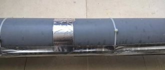
First of all, you need to disconnect the phase wire. Using a hammer or other tool, remove plaster or other finishing from the wall surface. It is necessary to clear the area along the route by approximately 10-15 cm, covering the area to the right and left of the expected center of damage. It is necessary to separate the damaged core from the network, being careful not to touch the insulation on other cables. It is better to connect copper wiring by soldering. To do this, you need to take an additional piece of a similar product from which the repair jumper is made. It is also advisable to first place a polyvinyl chloride or heat-shrink tube on the core of the damaged cable.
The ends of the jumper are twisted with the ends of the broken wire, after which the connections are soldered. Insulating tape is applied tightly (in several layers) to the repaired area, after which the tube covered with the wire is carefully pushed onto it. This ensures the tightness of the fastener.
Aluminum wires are less amenable to soldering, which also requires special solder and flux. In this case, the most reliable connection method will be the WAGO terminal, and the place of its attachment must be wrapped with electrical tape and additionally covered with sealant.
The wires can also be connected using a junction box. To do this, the insulation is removed from the broken wire, after which its ends are separated in different directions. Using a hammer drill equipped with a special crown, a hole is punched in the wall, the dimensions of which coincide with the parameters of the branch box.
The device is inserted into the opening, after which it is secured with alabaster. The wires are placed in the box, while the damaged wires are connected by color and wrapped with insulating tape. Finally, the box with the restored wires is closed with a lid.
If the cables are placed in special tubes, the damaged wires should be carefully pulled out, and new wires should be inserted in their place using a pulling device. If the neutral cable is damaged at the beginning of work, it must be disconnected from the bus by attaching the phase conductor
The rest of the process coincides with the regulations described above
If the neutral cable is damaged at the beginning of work, it must be disconnected from the bus by attaching the phase conductor. The rest of the process coincides with the regulations described above.
After any type of repair, the grooves are covered with plaster. It is possible to apply voltage to the repaired wiring only after the coating has completely dried.
Technical parameters of locators and locators
Locator and locator flaw detector can have different shapes, weight and cost. The pursuit of miniaturization of the locator leads to significant problems in the sensitivity and noise immunity of the device. Therefore, ERSTED locators and locators are balanced in terms of shape, weight and cost. The TI-05-3 locator and the TDI-05M3 locator in the lower price range have earned positive reviews throughout the entire period of release of their series. However, the most popular is the mid-price TDI-MA fault detector, which searches for cable damage even in conditions of abnormal interference from power lines or railways.
And of course, searching for cable damage using a fault detector is difficult without using a generator. Generators supply a current to the cable at a frequency consistent with the locator. That is why a cable detector can distinguish its cable from another route. According to their structure, generators are divided into two types, which is convenient to show using the example of generators:
- portable generators IZI;
- conditionally portable generators IZI-100.
Advantages of IZI generators
The IZI generator is a portable device that is easy to operate autonomously in the field. The generator develops power up to 6 W, which is a sufficient condition for searching for cable damage at a distance of up to 5 km. The IZI-100 generator is also a portable device, but it is designed to operate only from a 220 V network. Developing power up to 100 W, this generator is perfect for determining the location of interphase breakdown and short circuit. It is worth mentioning that these generators are presented in the low and middle price segment.
In conclusion, I would like to wish you good luck in finding cable damage, since well-chosen devices can only make this task easier, in which experience plays a major role.