One of the most important points when installing a SIP wire is to give it the correct tension.
When constructing VLI and VLZ, you can use modern and super-expensive tools and devices (motor winch), use reliable European fittings (Ensto and Sicame), but if you make a mistake in just one moment, roughly speaking, tighten the SIP more than required, and in a year all your the work will go down the drain.
The winter period of operation with our frosts does not forgive such mistakes.
Of course, any electrician understands that neither SIP, nor bare wires A or AC, and even modern innovative AEROZ cannot be pulled into a string.
Although this is visually beautiful from the outside, it significantly reduces the reliability of the operating overhead line. Even supports that can easily withstand large bending moments will begin to bend and tilt.
Or one of the anchor elements will not withstand the load and will break off. When installing the hook correctly on the support, the lock on the bandage tape must first come loose.
The SIP itself will fall to the ground without serious damage to the shell. But the installation of reinforcement is not always carried out using steel banding tape.
Through hooks are often used.
How to correctly calculate the tension of an insulated line with SIP wires, so that at low temperatures large bending moments do not appear, and the wire itself and the fittings are not subjected to increased loads?
Installation tables for SIP
Assembly tables will help you in this matter. They are present in almost any typical project.
You can view and download tables of tension and calculated sag (from Ensto) for SIP-4 wire from here (from page 32 to page 104).
However, do not forget to recalculate the mounting tension throughout the entire wire. Since the plates contain data on mechanical stress.
Also, to convert mPa into a more convenient format kgf or kN, used on dynamometer scales, you can use a convenient online converter using the link here.
Let's look at two extreme cases as an example:
- During installation, a minimum cross-section of 4*25 is used
- and vice versa maximum 4*120
From the tabular data you can clearly see how the SIP sag of a correctly tensioned wire changes depending on the temperature.
With a span length of 30 meters between the supports and a temperature of +20C, the sag should be about half a meter. The tension for the same wire does not exceed 84 kg.
This is not a very large value, and many are tempted to pull the line tighter. Fortunately, this can be done even manually by two or three fitters, without the use of special winches.
However, in winter, when the ambient temperature stays below 20 degrees for a long time and reaches -30C, everything changes dramatically. A correctly tensioned SIP with a cross section of 25mm2 already sags by only 14cm! And if you tighten it a little in the summer, then this is where the extra bending and tearing forces arise.
This is all transferred to the supports and anchor clamps. At -30C, the gravity increases 4 times and reaches 323 kg.
For SIP 4*120 at t=+20C, the sag will be 86cm. And at -30C it will rise to 0.6m. On the one hand, visually the difference here will not be so noticeable.
However, look at the gravitational force for yourself. Even in summer it exceeds 200 kg, not to mention the winter maximum or ice.
All these tables are designed in such a way that under any circumstances, even the worst (temperature minus 40C or minus 5C, but with ice), the gravitational forces are achieved to the maximum possible, but at the same time do not go beyond the norm.
That is, if in the summer under good weather conditions you pull the wires according to the table, and not “by eye,” then in the winter, even in the worst case scenario, nothing will break or break.
Installation tables and sag for high-voltage SIP-3 can be downloaded from here (Design Guide - Book 4.1 page 26-50).
The SIP wire itself is very durable. It differs significantly in its properties from the uninsulated bare speaker wire.
Therefore, you cannot pull it into a string.
If you do not have special measuring dynamometers, then it is better to let it sag. The main thing is to ensure clearance above the road.
At least there will be no overloads or emergency shutdowns due to this. And VLI-0.4 kV will quietly serve its allotted 40 years.
How to use these tables in practice in real conditions? In order to correctly stretch the SIP line along them, you can use two methods:
- use a dynamometer
- manually measure the sag in one span
Cable Sag Equation
A flexible homogeneous inextensible cable of length 2s is fixed at its ends at two points located at the same height and spaced from each other at a distance of 2l . It sags under its own weight.
The sag formula is expressed as follows:
where , where is the horizontal projection of the cable tension, and is the weight per unit length of the cable
Formula for the length of the arc, according to the shape of which the cable sags
The sag at the lowest point of the arc is calculated as follows:
In practice, the approximate formula is used
Where
SIP tension through a dynamometer
When using a dynamometer, the tension force taken from the table alone is not enough. It is also necessary to know the given anchor span. What it is?
This is a span or spans on an overhead line between two anchor supports. Between them there can be either one or several intermediate supports.
At the same time, the calculation tables indicate data specifically for the given spans. They represent a certain average mathematical value.
This is due to the fact that the lines are not always uniform. And the distances between the supports sometimes differ by several tens of meters.
Let's say you have two anchors and one intermediate support between them. The length of the first span is 40 meters, and the second is only 10 m. It is clear that with the same tension, in a larger span the sag of the boom will always be greater.
Therefore, the gravity itself is determined precisely for the average value. The average reduced span is calculated using the following formula:
- Li is the length of one span in meters or km
- ∑Li – sum of all spans
By calculating the value using this formula, you will get the final reduced span. For our case (40m+10m) it will be 25m.
Next, using interpolation in the table, we look for the required tension. In the tabular data for spans up to 40m, the values are divided in 2m increments.
For longer distances, integer values of 40-45-50m are usually used. You will need to find the closest one.
Having found out the required value, tension the SIP on the final support through a dynamometer.
In order to do this correctly, simply monitor the readings of the scale of the measuring device so as not to go beyond the limits of this effort.
Instructions for those on how to tighten a sagging conductor on a line
First of all, you shouldn’t panic or be nervous, but you also shouldn’t get close to the pillars.
Wait for the specialists to arrive and under no circumstances try to tighten the sagging cable and fix the problem yourself - this can result in very sad consequences.
Do not prop it up, and certainly do not try to cut off a piece of the cable to take it for yourself.
Damaged sections of lines pose a danger, even if there is no electricity in them (if you do not know what step voltage is, then read up, this information may later turn out to be vital).
Instructions for restoring power lines
- We disconnect the inputs, and also remove foreign objects, if any (tree branches, accidentally flying things like balloons, and so on).
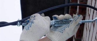
- We untwist the bands and release the wire, leaving it on the crossbars of the supports.
- We stretch the cable starting from the end anchor support. This is considered correct, since it has additional supports that are located along the lines and take part of the load upon themselves.
- We carry out the tensioning process using an aluminum conductor. It is advisable to take a piece measuring 20 meters. Using a bandage, it is connected to the damaged area and the insulator. After this, the tension itself occurs directly.
- We fix the main part to the insulator with an aluminum wire (we create three cores).
- We repeat the procedure with all insulators along the damaged line up to the extreme support point.
- After repairing the damaged parts, we connect the taps and check the line for operability and safety. Then, if everything is in order, we submit an application to the competent authority to obtain permission to connect electricity.
Note: SIP-type wires can be tensioned in the same way, but instead of an insulator we use special fittings for fasteners and anchors.
Attention! You can only tighten the area with a relatively small sag of the wires (0.5 meters is allowed). This is necessary due to temperature changes in winter and summer.
What actions should be taken to tighten the sagging area?
Contact the owner of the site or other person who is responsible for this territory and is responsible in case of emergency situations. Explain to him what is happening.
If it is not possible to contact him, then contact the Ministry of Emergency Situations, the energy supply organization, the local administration or any other authorized body.
Step-by-step installation of SIP cable from pole to house: 12 stages
In order to install a SIP cable from a pole to a house, it is better to seek help from professionals. Installation of a SIP cable from a pole to a house is carried out when it is necessary to insert a power cable into a separate building. Before the start of construction and installation work, design and estimate documentation is drawn up. It takes into account the required power, technical characteristics of the wire, the selected installation technology and standards for safe operation. The more pedantry the builder shows, the less he risks his own life and health.
Experienced and less experienced builders always pay attention to the positive and negative aspects of any technological solution. When it comes to SIP, self-supporting insulated wire, the first thing people immediately pay attention to is the aluminum conductors.
Thanks to this, the system is less susceptible to the destructive effects of the vagaries of nature and even minor sagging and tension.
The insulating coating has experimentally proven resistance to aggressive environments and frequent temperature changes.
If we talk about other advantages, they look like this:
- Ease of installation;
- Easy to maintain;
- Possibility to save the area required for laying a high-voltage line;
- It can be placed on supports in direct sunlight for several days without compromising the integrity of the insulation;
- The guaranteed service life is at least four decades.