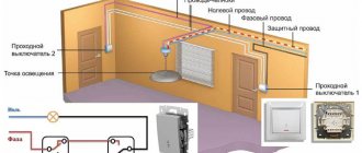
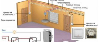
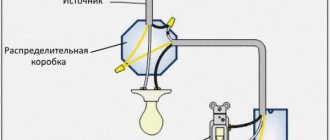
Connection diagram for a two-key pass-through switch used quite often in residential and public buildings. It is known that in spacious rooms or long corridors it is extremely inconvenient to use only one switch installed at the entrance itself.
For some time before turning on the device or after turning it off, you will have to do without light. There is only one way to avoid this inconvenience - to install devices of a special design at the entrance to the room, as well as at its exit (they are called pass-through switches or switches).
Design and principle of operation
With the help of such switches, it is possible to control the same light source from two or more points, turning it on in one place and turning it off in another (or vice versa). Thanks to this, while moving, the corridor will be constantly illuminated along the entire path.
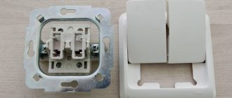
The rear view of two-key pass-through switches from different manufacturers is shown in the figure below.
The connection diagram for a double pass-through switch can be implemented using a single-key device, so the question is quite logical: what is the second key for then?
To answer this you will need to understand the following explanations:
- A two-key pass-through switch also contains changeover contacts, but in this case the number of switching groups of lamps increases from one to two .
- The number of conductors connecting two spatially separated switching devices increases to 4.
- With this connection diagram for two-key pass-through switches, it becomes possible to switch two lighting bulbs at once (one to turn on and the other to turn off).
- To see the difference between two-key and single-key switches, a direct comparison will help us. To do this, you will need to remember the connection diagram for the pass-through switch, in which the connection is made on only two wires.
Important! When examining the two schemes together, one can immediately see the difference not only in the number of connectors, but also in the functionality of the devices used.
If in the case of a single key only one group was switched (the lamp was turned on and off), then in a chain with a two-key switch there are already two such groups. According to the diagram of two-key pass-through devices, in this situation it will be possible to turn on the first of 2 light bulbs while simultaneously turning off the second and vice versa.
Preferential placement places
Pass-through switches are installed in any places accessible to hands. It is not necessary to constantly use both devices to control lighting. One switch can be the main one, and the second can be used only when necessary.
If the wires of conventional switches were laid in corrugation, then it is possible to replace them with pass-through ones without damaging the walls
Mostly DPVs are installed in the following places:
- At opposite ends of a long corridor. If there is an additional door in the middle, then a limit switch can also be placed near it.
- In large bedrooms. One DPV can be placed classically on the wall near the door, and the other by the bed.
- On flights of stairs.
- On paths and paths of houses, cottages, dachas. It is convenient to leave the house in the evening, walk along the illuminated alley and turn off the light near the entrance gate.
- In large halls with several entrance doors on opposite sides.
The pass-through switch simultaneously saves energy and ensures the safety of people's movement. The only disadvantage of this device is the increased complexity and cost of initial installation.
Lighting control scheme from two places
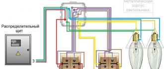
By connecting double pass-through switches, it is possible to control two light bulbs alternately from two places. This circuit contains a pair of two-key switches, which allows you to turn on one of the lamps at the entrance, while simultaneously turning off the other. When exiting a long corridor, for example, a second device allows the reverse operation. Thus, lighting control is carried out alternately from 2 places.
Important! In this case, the direction of movement along the corridor is not of fundamental importance.
It is possible to implement such a control algorithm only if there is a double pass-through switch. Systems organized in this way significantly simplify lighting control in the conditions described above.
Installation procedure
Before connecting pass-through two-key switches and illuminators, places for their installation are first selected (the first ones should be located at the very exit-entrance to the room). After this, they move on to the main work, carried out in the following sequence:
- First of all, at selected points, installation niches are drilled into the walls with a special crown, the diameter of which is selected to be 72 or 80 mm (depending on the device housing).
- Then special plastic boxes are fixed into them (they are called “socket boxes”).
- When laying the wiring externally, the housings of the switching products are mounted on the wall using self-tapping screws.
- Upon completion of the installation of two-key pass-through switches, proceed to the installation of two groups of illuminators, in each of which the lamps are switched on in parallel (this will eliminate the possibility of a complete blackout of the circuit if one of them burns out).
- Then, two phase wires and one neutral wire are laid from the installed chandeliers or lampshades to the distribution box.
Since the requirements of the PUE require grounding of any connecting wiring with loads, a cable with three cores is laid from the lamps.
Please note: It is recommended to choose the location for installing the distribution box (RC) in the middle of the room, which allows you to save on the length of the wires.
Since the design of the two-key pass-through switch has 6 contact terminals, two 3-core cables will need to be laid from it to the switch. When disconnecting system elements, the wires to the RC must be connected according to the diagram below.
We suggest watching a video on how to connect two-key pass-through switches without a junction box.
Attention! In this installation option, the socket boxes must be deep.
Preparatory work before connection
In almost all cases, when installing two-key electrical installation products, additional wiring and installation of additional equipment will be required. And all this, most likely, will have to be purchased.
So, at the preparation stage you will need:
- Two three-wire wires of the required length for each switch. It is important that its cross-section is at least 2.5 mm². It is also important that copper is used as the manufacturing material. We recommend that you familiarize yourself with the rules for choosing wires for home wiring.
- Junction box . It is needed because the cable from the pass-through switch, for safety reasons, cannot be laid directly to the lighting fixtures. It should be remembered that there will be many connections, so the volume of one standard box is unlikely to be enough. Therefore, even before starting work, you should think about purchasing paired products.
- Installation box , which is also called a socket box. Such devices are used to accommodate the pass-through switches themselves.
The wire is laid in an open or closed way. But in any case, before starting installation, the purchased electrical cable should be checked for functionality.
The photo shows a model of the lighting control system, which allows you to get an idea of what should come out during the installation of two-key switches
When checking the cable, you first need to perform an external inspection, and then ring it using special equipment, for example, a multimeter.
If you ignore this rule, you can suffer significant losses. This is especially true for cases where the wire will be mounted into the wall.
If it is possible to ground the pass-through switch, then it should be used. This applies to cases where a PE bus is provided. It is usually available in new buildings.
When performing connection work, safety precautions must be observed. So, before starting the procedure, you should turn off the power to the room. .
Lighting control scheme from three places
In order to control lighting from three places at once, the previously used scheme with two two-key devices will need to be supplemented with one more (it is called cross). This switch can be placed anywhere in the room between two already installed products.
Structurally, a cross double pass-through switch consists of two two-key devices combined in one housing. In this product, instead of two, one common key is installed on a conventional changeover mechanism, due to which the switching of both lines is carried out synchronously.
The 3-point connection diagram is organized in such a way that the neutral wire is supplied to both lighting groups at once, and the phase wire is supplied to each of the inputs of the first two-key switch. Regardless of the position of the keys, current will flow only through 2 of the 4 input terminals. From the first pass-through switch, the current flows through the jumpers to the input of the cross switch, and then to the second pass-through switch.
This position of the switch keys determines the path of current through the lighting fixtures. If this group is in working condition (the lights are on), just press the key of any of the switches to remove power from it. The same thing happens when they are turned on: when you change the position of any key, the power circuit is immediately restored.
Method number 1. Two-key switch
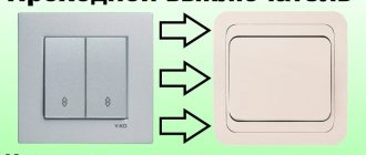
This method allows you to obtain pass-through switches from conventional two-key models. This is especially convenient if you don't want to spend time making complex changes to their design or don't have the appropriate tools.
Rice. 2. Two-key model of pass-through switch
To implement this model of a pass-through switch, you will need two two-key devices, connecting wires and a lighting source.
Once you have collected everything you need, follow these steps:
- Turn off the voltage on the panel using a circuit breaker - this will prevent electric shock during installation work. It will be more reliable if you simultaneously disconnect both the neutral and phase conductors for the corresponding lamp.
- Connect the first of the two-gang switches to the phase wire of the three-core cable. To do this, release the terminal on the switch and insert the core there. The core is clamped until reliable contact is obtained with minimal resistance to electric current.
- Also connect a wire to each of the output contacts. Next, lead them to the output contacts of the second two-key switch.
- From the input terminal of the second switch, take the wire to the lighting device.
If the lighting system is carried out as part of a major overhaul and replacement of all lamps and appliances in the house, then the walls are tapped for power distribution. Otherwise, you can get by with external installation in the cable channel. In case of a long distance between switching points, it is better to carry out wiring with a three-core cable. Since three wires are optimally used for intermediate connection of wires.
It should be noted that the above method works by simultaneously switching two keys at once, so each time you need to operate two buttons at once, moving them to opposite positions.
Otherwise, the logic of the circuit will be broken and next time you simply will not be able to turn off the light bulb. Therefore, if other household members may be negligent about such switches, it is better to redesign the device to a single-key version.
Four-place lighting control circuit
To organize control of lighting devices from 4 points at once (in two directions) in the room, you will need to install a couple of cross switching products. If there are several lighting groups, preference is given to two-key cross-type switches. When they are connected in series, not only the electrical wiring becomes more complicated, but also the installation of the products themselves according to the algorithm already discussed above.
In this case, jumpers will need to be installed twice (in both pass-through switches, the diagram of which is shown above). When disconnecting such systems, it is recommended to strictly follow the sketch drawn in advance with the designations of the contacts and jumper conductors indicated on it.
Scheme for connecting the 3rd and subsequent switches
According to the connection diagram, when using 2 switches, it becomes clear that pass-through switches can only be used in pairs and it will no longer be possible to connect a third such equipment.
This problem is solved by using a crossover (reversing) switch - it does not differ in appearance, but uses four terminals for connection.
As the name implies, its main purpose is to swap connected wires. To understand the principle of operation, it is best to look at a connection diagram with 3 or more switches.
Connection diagram for a three-key pass-through switch
When familiarizing yourself with the diagram of a pass-through three-key switch, you need to pay attention to the following points:
- The devices in question have 6 output contacts, which allows you to control three groups of illuminators while being at one access point.
- Before connecting a pass-through switch with three keys, you will first need to mount its loads and disconnect them according to the lighting plan.
- The three-key pass-through switch, the diagram of which is shown in the figure on the right, is not intended for pass-through purposes.
- The main purpose of these devices is to save on wiring costs by controlling multiple illuminators from a fixed point.
In conclusion, we note that the technique of installing a two-key pass-through switch from two places and all its subsequent modifications (from three and four points) resembles the same operations for single-key devices. Its slight complication is justified by a significant expansion of the system’s functionality, supplemented by another illuminator, switched “out of phase” with the first.
Installation of distribution box
When installing the DPV, all wires must be concentrated in the distribution box. This will reduce the number of grooves and simplify the maintenance of electrical wiring if the number of lamps or their switching pattern changes.
It is advisable to place the junction box between two limit switches at the level of the lighting fixture located in the center of the room. However, the final choice of installation location is made based on the specific configuration of the room and the placement of electrical circuit elements.
Self-clamping terminals provide a tight connection whose strength does not change over time. They are safe and easy to use
The worst option for connecting wires in a distribution box is ordinary twisting with electrical tape. This method can lead to heating of the insulation and subsequent fire. It is best to connect the cores using special terminals, because they provide ease of installation and subsequent maintenance.
