Direct and reverse phase rotation
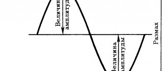
Three-phase alternating current is graphically represented by three phases in the form of alternating sinusoids on the X-axis, shifted relative to each other by 120°. The first sine wave can be represented as phase A, the next sine wave as phase B, shifted 120° relative to phase A, and the third phase C, also shifted 120° relative to phase B.
Graphic display of phase shift for 120° three-phase network
If the phases have the order ABC, then this sequence of phases is called direct alternation. Consequently, the order of the SVA phases will mean reverse alternation. In total, three direct alternations of phases ABC, BCA, CAB are possible. For reverse phase rotation, the order will look like CBA, BAC, ACB.
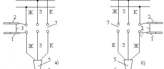
You can check the phase rotation of a three-phase network using a phase indicator FU - 2. It is a small case on which there are three clamps for connecting three phases of the network, an aluminum disk with a black dot on a white background and three windings. Its operating principle is similar to that of an asynchronous electric motor.
If you connect the phase indicator to three phases and press the button on the housing, the disk will begin to rotate in one direction. When the rotation of the disk coincides with the arrow on the body, then the phase indicator shows direct phase rotation; rotation of the disk in the opposite direction indicates reverse phase rotation.
Electrical circuit of the phase indicator FU-2
In what cases is it necessary to know the order of phase rotation? Firstly, if the house is connected to a three-phase network and an induction electric meter is installed, then direct phase rotation must be observed on it. If such an electric meter is connected incorrectly, it may self-propel, which will give incorrect readings in the direction of increasing electricity consumption.
Also, if asynchronous electric motors are used in the house, the direction of rotation of the rotor will depend on the order of phase alternation. By changing the phase sequence on an asynchronous electric motor, you can change the direction of rotation of the rotor in the desired direction.
How does ECMO work?
The word extracorporeal means “outside the body.” In general, ECMO is an artificial blood circulation system - the device pumps and oxygenates the patient's blood outside his body. This procedure is performed in cases where all other treatments have already been tried. When a person is connected to ECMO, blood is supplied by a pump to an artificial lung - an oxygen generator . Technically, an oxygenator is a device that supplies the blood with oxygen and removes carbon dioxide. When the patient recovers from critical illness, he is disconnected from ECMO.
In simple words , if mechanical ventilation pumps pure dry oxygen into the lungs and removes carbon dioxide from them, then ECMO takes on all the functions of the lungs in saturating the blood with oxygen and removing carbon dioxide from them. Blood is taken from the patient (through the veins), enters the ECMO machine, is cleared of carbon dioxide, saturated with oxygen and returned to the patient.
What is phasing of a three-phase network
The phasing of three phases is carried out in transformer substations with parallel connection of transformers. The connection of two transformers to one three-phase network is carried out by cross-sectional circuit breakers. It is not possible to check the phases of the same name with a phase indicator.
However, you can determine the phases of the same name with a multimeter or any voltmeter with a measurement limit of 500 V. When carrying out phasing, you must follow all safety measures and check the multimeter in advance for functionality. Before finding phases of the same name, it is important to determine the presence of phase voltage relative to ground on all buses (in case of a break).
Checking for open circuit and finding phases of the same name in a three-phase network
Next, working with rubber gloves, measure the linear voltages on the buses of different transformers. If buses are found, the voltage between which is near zero, then such buses have the same phases and they are marked. Next, they find the remaining two pairs of tires of the same name and also mark them.
If the voltages between all buses of different transformers are below linear 380 V, but differ significantly from zero, then such transformers cannot be phased, since they have different connection diagrams. The found buses of the same name are connected to disconnectors for parallel operation.
The difference between phase and line voltage in a three-phase network
When the transformer has different voltages, with the same connection diagrams, they are adjusted using a tap switch of the transformer windings to the rated value. Phasing of high-voltage lines is carried out with special high-voltage indicators UVNF.
Source: electricavdome.ru
PHASING OF CABLES OF RADIAL LINES AND HIGH VOLTAGE JUMPERS
Phasing of high-voltage cables is carried out using a high-voltage voltage indicator or voltage transformers, including portable ones, used in installations up to 10 kV. For phasing, two voltage indicators are used (Fig. 9). In one of them, instead of a capacitor and a neon lamp, ohmic resistances of 3-4 MOhm (for 6 kV) and 5-7 MOhm (for 10 kV) are inserted inside.
One end of the phased cable is connected to a voltage source. Phasing is done at the terminals of the disconnected switch at the other end of the cable. Before phasing, you must first touch the hook of the tube with the neon lamp to the live part. In this case, the lamp should light up. Then, without removing the first hook, touch the same part with the hook of the second tube with resistance.
Rice. 9. Phasing of cables and cable jumpers with voltage up to 10 kV using the indicator method with additional resistance. The lamp should go out. This checks the proper operation of the device. After this operation, the hook of the pointer is brought to the bus terminal of the switch, and the hook of the tube with resistance is brought to the cable terminal. The burning of the lamp shows that the phases are of the same name, and its extinction indicates that the phases are of the same name. The pointer hooks and resistance tubes are brought within 1-2 cm of the corresponding clamps that need to be phased. If there is a glow, the duration of the indicators being energized due to the low thermal stability of the resistances built into the tube should not exceed 10-15 seconds. To more accurately determine the potential difference in the absence of glow, it is allowed to touch the hooks of the tubes to the clamps of the devices, between which the phasing is checked.
The conductor connecting the voltage indicator to the additional resistance tube must be flexible, have reliable insulation (for example, auto-tractor wires of the PVL and PVG types) and tips adapted for connection to the metal clamps of the voltage indicator. Tubes with added resistance must be clean, stored in special cases, indoors and subject to periodic testing in the laboratory along with other safety equipment.
Rice. 10. Line phasing diagram using stationary voltage transformers. Persons performing tests must wear rubber gloves and boots tested in accordance with current standards.
Using stationary voltage transformers (Fig. 10), you can phasing circuits of any voltage. According to the diagram in Fig. 10, and when the section switch is turned on and the phased line is disconnected, the phasing of the voltage transformer is first checked. According to the diagram in Fig. 10b, with the section switch turned off and the phased line switched to the reserve section, the line is phased with the bus system. A zero voltmeter reading indicates the same phases of the line and bus system. According to this scheme, instead of voltage transformers, power transformers can be used, having the same group of connections and powered from different sections.
Rice. 11. Phasing of the cable line and jumper using a portable measuring voltage transformer.
A single-phase measuring voltage transformer, designed for linear voltage, is connected alternately between the phase terminals of the busbar system and the phased cable using insulating handles (Fig. 11). A zero reading on the voltmeter indicates that the phases are identical.
Checking the phase rotation of power cables
Simple cable phasing methods
The simplest way to find current-carrying conductors at the end of a cable that correspond to certain phases of its beginning is to check the “continuity” of the cable conductors using telephone handsets, for example, when checking power cables laid between different rooms of stations and substations. The connection diagram for telephone handsets is shown in Figure 1.
As one of the wires for establishing communication, grounded structures (grounded metal sheath of the cable) are used, to which telephone handsets are connected. Next, on one side of the cable, the wire from the battery is connected to a current-carrying core (for example, phase C).
Diagram for connecting telephone handsets with cable phasing
On the other side of the cable, the second wire from the handset touches the current-carrying wires one by one, each time sending a voice signal into the handset. Having found a vein for which the inspector's review will be received, it is marked as phase C and the search for other veins continues in the same order. Instead of ordinary telephone handsets, it is advisable to use telephone headsets, the use of which frees up the hands of inspectors for work.
To check phase rotation, a megohmmeter is widely used, the connection diagram of which is shown in Figure 2. To do this, the conductors at the beginning of the cable are grounded one by one, and at the end the insulation resistance of the conductors relative to the ground is measured.
Megger connection diagram for cable phasing
A grounded conductor is detected by the readings of a megohmmeter, since the resistance of its insulation to the ground will be zero, and the other two conductors will be tens or even hundreds of megaohms.
With this test method, ground connections are installed and removed three times. In addition, personnel located at the ends of the cable must communicate with each other in order to coordinate their actions. All this refers to the disadvantages of this method of verification.
A more advanced method of cable phasing is the measurement method according to the diagram shown in Figure 3.
One of the three cable cores (let's call it phase A) is rigidly connected to a grounded shell, the other core (phase C) is grounded through a resistance of 8-10 MOhm. A tube with UVNF indicator resistors is usually used as a resistance. The third core (phase B) is not grounded; it remains free. At the other end of the cable, the resistance of the conductors relative to the ground is measured with a megohmmeter.
Obviously, phase A will correspond to a conductor whose resistance to ground is zero, phase C will correspond to a conductor having a resistance to ground of 8 - 10 MOhm, and phase B will correspond to a conductor with infinitely high resistance.
Connection diagram for a megohmmeter and an additional resistor when phasing the cable
Safety precautions when producing cable phasing
According to safety conditions when phasing cables, phasing is performed only on a cable line that is disconnected on all sides. In this case, measures must be taken to prevent the supply of operating voltage to the cable. Before starting phasing using a megohmmeter, all personnel located near the cable are warned not to touch live conductors.
The connecting wires from the megohmmeter must have reinforced insulation (for example, PVL type wire). They are connected to the current-carrying conductors after the cable has been discharged from the capacitive current. To remove the residual charge, the cable is grounded for 2-3 minutes.
Checking the phase rotation of power cables based on the color of the core insulation
The current-carrying conductors of power cables with insulation made of impregnated paper are colored with ribbons of colored paper wound around their insulation. One of the cores, as a rule, is surrounded with red tape, the other with blue, and the insulation of the third is not specially colored - it retains the color of the cable paper.
Methods for determining the integrity of cores, the nature and location of damage to cable lines
Determining the integrity of the cores, the nature and location of damage to cable lines (in the general case, determining the location of damage (LOD)) is divided into three main stages:
- diagnostics of damage, that is, determination of the nature of cable damage. At this stage of the WMD, the need for preliminary burning is established;
- determining the area of suspected damage using one of the relative methods;
- clarification of the location of the damage using one of the absolute methods.
The cable line OMP method is selected depending on the nature of the damage. Cable damage can be divided into the following types:
- insulation damage causing a single phase to ground fault;
- insulation damage causing a short circuit of two or three phases to ground or two or three phases to each other;
- breakage of wires of one, two and three phases (with or without phase grounding);
- floating insulation breakdown;
- complex injuries, representing combinations of the above types of damage.
To determine the nature of the damage to the cable line, you should:
- measure the insulation resistance of each current-carrying conductor in relation to ground;
- measure the insulation resistance between a pair of current-carrying wires;
- measure the electrical resistance of current-carrying conductors;
- determine the integrity (absence of breakage) of current-carrying conductors.
Measurements are made on a cable line, which is disconnected from the power source and all electrical receivers are disconnected from it.
It is recommended to measure the insulation resistance of cable lines with a megohmmeter for a voltage of 2500 V. DC bridges can be used to measure the electrical resistance of current-carrying conductors. If the ambient temperature T during measurements differs from 20℃, then after the measurement the resistance is recalculated to a temperature of 20℃ using the formula:
where ??ρ is the average value of the temperature coefficient of resistivity.
The obtained resistance value is used to determine the length of the cable section under study
where ρ is the electrical resistivity of the material from which the current-carrying conductor is made; ? – coefficient taking into account the effect of twisting of wires in the core, (? = (1.02 ÷ 1.03); ? – core cross-section.
Numerical values of the geometric parameters of sectored aluminum conductors of cables with voltages of 1 – 10 kV are given in table. 2.
Table 2. Parameters of sectored aluminum conductors of cables with voltage 1 – 10 kV
| Cable and core design | Height h, mm / width b, mm for cores with cross-section | |||||||
| 35 | 50 | 70 | 95 | 120 | 150 | 185 | 240 | |
| Three-core single-wire, 1 – 10 kV | 5,5 9,2 | 6,4 10,5 | 7,6 12,5 | 9,0 15,0 | 10,1 16,6 | 11,3 18,4 | 12,5 20,7 | 14,4 23,8 |
| Three-core stranded, 1 – 10 kV | 6 10 | 7,0 12,0 | 9,0 14,0 | 10,0 16,0 | 11,0 18,0 | 12,0 20,0 | 13,2 22,0 | 15,2 25,0 |
| Four-core single-wire, 1 kV | − − | 7,0 10,0 | 8,2 12,0 | 9,6 14,1 | 10,8 16,0 | 12,0 18,0 | 13,2 18,0 | − − |
After determining the nature of the damage to the cable line, a method is selected to determine the location of the damage in this particular case. It is recommended to first determine the area in which the damage is located. The damage zone is determined using one of the following relative methods: pulse (location), oscillatory discharge (wave) or loop.
The loop method is based on the fact that the damaged and “good” cable cores are short-circuited on one side (a loop is formed); on the other hand, additional adjustable resistors are connected to the ends of the cores - a bridge circuit is created. To use the loop method, you must have at least one intact cable core or at least one core with a transient resistance that is significantly higher than the transient resistance of the other two cores (10 - 100 times). The value of the transition resistance of the core should be no more than 5000 Ohms.
The loop method reliably tests single-phase and two-phase short circuits of a stable nature. Three-phase faults are determined in the presence of an additional wire, which can be used as a parallel cable.
There are known methods for determining the location of cable damage using the Murray loop and Varley loop scheme. The Murray loop method (Fig. 9) is used if, in a certain place, one of the cable cores is shorted to another or to the shell through a transition resistance ?n, the value of which does not exceed 104 Ohms. To more accurately determine the location of the damage, measurements are taken from both ends of the cable.
Rice. 9. Measurement diagram for determining the distance to the place of cable damage using the Murray loop method : 1, 2, 3 – cable cores; 4 – jumper;?п – transition resistance; ENI – indicator
From the equilibrium condition of the bridge it follows:
where R is the resistance of the bridge arm connected to an undamaged core (decades P1 - P4);
M – resistance of the bridge arm connected to the damaged core (counting over the ten-day P5 relationship ?⁄?);
r – cable core resistance;
?? – resistance of the cable core to the point of damage.
With a constant cross-section of current-carrying conductors, the resistance of the segments is proportional to the length of the corresponding sections. The distance to the damage site is found from the expression
where L is the length of the cable line.
Measurements to determine the location of the fault should be made from both ends of the cable line, changing the location of the jumper. The results obtained can be assessed based on the equality
The measurement error is calculated using the formula
The measurement scheme using the Varley loop method is shown in Fig. 10.
Rice. 10. Measurement diagram for determining the distance to the place of cable damage using the Varley loop method : 1,2,3 – current-carrying cable cores; 4 – jumper
The measurement results are determined by the formula:
where r is the resistance of two cable cores, Ohm;
R – resistance of the comparison arm (decades P1 – P4);
n – multiplier installed on the decade of bridge P5.
?1, ?2 – resistance of the decade of bridge P5, determining the values of the factors m and n.
The distance to the point of cable damage is found from the expression
where S is the cross-section of the conductor, mm2,
ρ is the resistivity of the cable core material, Ohm mm2/km. Measurements should also be made from both ends of the cable line, changing the location of the jumper.
When current-carrying conductors break, a capacitive method is used to determine the location of damage, based on measuring the capacitance of the conductors in relation to each other or in relation to the ground. The capacitive bridge diagram is shown in Fig. eleven.
Rice. 11. Measurement scheme for determining the location of damage using the capacitive method
From the equilibrium condition of the bridge it follows:
where M and R are adjustable resistances,
?? – determined cable line capacitance, μF,
Δn is the capacitance of the reference capacitor, μF.
Based on the measurement results of the capacitance of a working core ?? and the capacity of the damaged core?? you can determine the length of the cable section, km:
where ?sp is the specific capacitance.
The capacitance of cable line sections is measured at both ends. The distance from the measurement point to the point where the cable core is broken is determined by the relation
where ?1 and ?2 are the results of the first and second measurements, μF.
A short introduction
A story about the installation of electrical equipment, namely two oil transformers, caught my eye. The work was completed successfully. As a result, there was the following power supply scheme. Actually the transformers themselves, input switches, sectional disconnectors, two bus sections. According to the installers, the commissioning work was completed successfully. They started switching on both transformers for parallel operation and got a short circuit. Naturally, the installers claimed that they had checked the phase rotation from both sources and everything matched. But not a word was said about phasing. But in vain! Now let's take a closer look at what went wrong.
What is phase alternation?
As you know, in a three-phase network there are three opposite phases. Conventionally, they are designated as A, B and C. Remembering the theory, we can say that the phase sinusoids are shifted relative to each other by 120 degrees. So, there can be six different alternation orders in total, and they are all divided into two types - direct and reverse. The following order is considered direct alternation - ABC, BCA and CAB. The reverse order will be CBA, BAC and DIA, respectively.
To check the order of phase alternation, you can use a device such as a phase indicator. We have already talked about how to use the phase indicator. Let's look specifically at the sequence of checking with the FU 2 device.
How to check?
The device itself (shown in the photo below) consists of three windings and a disk that rotates during testing. It has black marks that alternate with white ones. This is done for ease of reading the result. The device operates on the principle of an asynchronous motor.
So, we connect three wires from a three-phase voltage source to the device terminals. Press the button on the device, which is located on the side wall. We will see that the disk begins to rotate. If it rotates in the direction of the arrow drawn on the device, it means that the phase sequence is direct and corresponds to one of the order options ABC, BCA or CAB. When the disk rotates in the opposite direction of the arrow, we can talk about reverse alternation. In this case, one of these three options is possible - CBA, BAC or DIA.
If we return to the story with the installers, then all they did was just determine the sequence of phases. Yes, in both cases the order was the same. However, it was still necessary to check the phasing. And it cannot be done using a phase indicator. When turned on, opposite phases were connected. To find out where A, B and C are conditionally, you had to use a multimeter or oscilloscope.
A multimeter measures the voltage between the phases of different power sources and if it is zero, then the phases are the same. If the voltage corresponds to the linear voltage, then they are different. This is the simplest and most effective way. You can find out more about how to use a multimeter in our article. You can, of course, use an oscilloscope and look at the oscillogram which phase lags behind which by 120 degrees, but this is impractical. Firstly, this makes the technique an order of magnitude more complicated, and secondly, such a device costs a lot of money.
When should order be considered?
It is necessary to check the phase rotation when operating three-phase AC motors. The order of the phases will change the direction of rotation of the motor, which is sometimes very important, especially if there are many mechanisms on the site that use motors.
It is also important to take into account the order of the phases when connecting a CA4 induction type electric meter. If the order is reversed, a phenomenon such as spontaneous movement of the disk on the counter is possible. New electronic meters, of course, are insensitive to phase rotation, but a corresponding image will appear on their indicator.
If you have an electrical power cable with which you need to connect a three-phase power supply, and you need phasing control, it can be done without special devices. Often the cores inside the cable differ in the color of the insulation, which greatly simplifies the “dialing” process. So, to find out where phase A, B or C is conventionally located, you only need to remove the outer insulation of the cable. At both ends we will see veins of the same color. We will accept them as the same. You can learn more about color coding of wires from our article.
But still, you cannot blindly trust such markings. So, in practice, there are cases that cable manufacturers cannot guarantee that the color of the cores at the beginning and end of the cable will be the same. Therefore, you still need to ring the wires with a ringer.
Now you know what phase rotation is in a three-phase network and how to check it using instruments. We hope the information was useful and interesting for you!
We also recommend reading:
Source: samelectrik.ru
Checking the phasing of electrical equipment
Three-phase electrical equipment (transformers, generators, cable power lines) is subject to mandatory phasing before it is first connected to the network or after the completion of the next repair, as a result of which a violation of the sequence of phases could occur.
Phasing consists of checking the phase coincidence of the voltages of each of the 3 phases of the electrical installation being switched on with the corresponding network voltages. This kind of check is certainly necessary, because during the assembly, installation and repair of electrical equipment, the phases could be rearranged.
In electric machines, for example, it is not excluded that the power terminals of the stator windings are incorrectly designated; Cables in connecting couplings can have conductors of opposite phases connected to each other.
In all these cases, the only way out is to perform phasing. As a rule, this technological operation consists of 3 main stages listed below.
Checking and comparing the phase sequence of an electrical installation and network
. This operation is performed before directly switching on parallel operation of several networks operating independently, a new generator and a generator that has undergone a major overhaul, during which the connection diagram of the stator windings to the network may have changed.
Only when positive results obtained from phasing are obtained, generators or, say, transformers are synchronized and switched on for parallel operation.
Checking the identity or color of phase conductors
, which will subsequently need to be connected. This operation aims to check the correct connection of all installation elements to each other. Simply put, the correctness of the supply of current-carrying conductors to the switching device is verified.
Checking the phase coincidence of voltages of the same name
, that is, the absence of a phase shift angle between them. In electrical networks, when phasing power lines and power transformers that belong to the same electrical system, it is enough to perform the last 2 operations, since all generators operating synchronously with the network have the same phase order.
Phasing devices
. Today there are many techniques that depend on the intended purpose of the electrical equipment, the winding connection diagrams and the devices and devices used. The main instruments and devices include:
AC Voltmeters
, used for phasing electrical installations up to 1 kV and connected directly to the terminals of electrical equipment.
Phase indicators
, the principle of operation of which is similar to the principle of operation of an IM (asynchronous motor), when when a coil of devices is connected to a 3-phase current network, a rotating magnetic field is formed, which causes the working disk to rotate. In this case, by the direction of rotation of the disk, one can judge the correct order of the phases of the currents passing through the coils.
Universal devices (portable volt-ampere phase indicators, universal phase indicators)
.
Megaohmmeters
, which are portable devices necessary for measuring insulation resistance in wide ranges, which have proven themselves very well in the production of phasing.
Voltage indicators
for phasing. These devices are well suited for phasing electrical installations above 1 kV. When performing an operation on a disconnected device (disconnector, circuit breaker), phased voltages are supplied to each side.
At the same time, the probes of the device are brought to the current-carrying parts of the phased device, and then the glow of the signal lamp on the device is monitored.
It is worth considering that the burning of the lamp indicates a phase mismatch, and the absence of the light of the lamp indicates consistent switching on and the possibility of switching on the switching device.
Phasing methods
. This operation may be preliminary; performed during installation and repair of electrical equipment, and phasing immediately before commissioning, carried out before the first switching on of the equipment, when the phases could be swapped.
Source: forum220.ru
What testing devices are there?
There are two ways to perform a phase check:
- straight. A method in which testing is carried out at the inputs of electrical appliances that are under operating voltage. It is usually used for devices up to 110 kV;
- indirect. A method in which the process is carried out using secondary electrical voltage. This test is usually performed in the presence of voltages of 110 kV and above.
Transformer phasing diagram with jumper installation. There are not many devices used in testing. Popular among them:
- voltmeters. Typically used in devices with voltages up to 1 kV. They connect directly to equipment terminals or parts of devices that conduct current. As for accuracy, it is not required from such devices;
- phase indicator. The sequence of phases and their order are determined by induction phase indicators. They consist of several coils, inside of which there are ferromagnetic cores and an aluminum disk. The principle of operation of the device is similar to the operation of an asynchronous type electric motor. When it is connected to a three-phase network, all coils begin to rotate the electromagnetic field around them. Because of this, the disk begins to rotate, which shows the phase sequence of the network.
You may be interested in this Features of casings for wires
What is phase rotation?
Phase alternation should be understood as the sequence in which the voltage increases in each of them. In all three-phase circuits, the voltage is a sinusoidal curve. In each line the voltage differs by 120º from the others.
Rice. 1. Voltage in three-phase network
As you can see, in Figure 1, where a) shows the voltage curves in all phase wires, shifted by 120º. The adjacent figure b) shows a vector diagram of these voltages. Both figures show the difference between phase and line voltage.
If we take as a basis that UA comes out from the zero point in figure a), then this phase is the first; in diagram b), the arrows clearly show that the order of voltage increase goes from UA to UB, and then to UC. This means that the phases alternate in the order A, B, C. This order of alternation is considered direct.
Direct and reverse phase rotation
In a three-phase network, the order of phase rotation may differ depending on the connection methods to power transformers at substations, the sequence of switching on the generator windings, due to mismatch of cable terminals and other reasons.
Why do you need to consider phase order?
The sequence of alternations plays a significant role in such situations:
- When connected in parallel, a number of devices (transformers, generators and other electrical machines) can be connected in parallel operation to increase the reliability of the system or to provide a greater power reserve. But, in case of incorrect connection, a short circuit will occur due to the connection of opposite phases.
- When connecting a three-phase meter - since its operation is based on the coincidence of phases with the corresponding terminals of the device, then if the connection is not correct, a failure and spontaneous movement may occur in the absence of any load. Because of this, such a connection of the electric meter will lead to the need for the consumer to pay for kilowatts that he did not consume.
- When the engine is turned on, the sequence of phases in the network determines the direction of rotation of the engine for the electric machine. In the absence of correct phasing, the direction of movement of the elements mechanically connected to the rotor will also change. This could result in a disruption of the technological process or a threat to the lives of personnel.
In order to prevent negative consequences from phase imbalance and other mismatches, in practice, they check the alternation and install protection.
How to check?
Checking can be done in several ways. The feasibility of choosing one or another option depends on the parameters of the electrical network and the problems that need to be solved. So the alternation can be recognized using a phase indicator, megohmmeter, multimeter or by the color of the cable insulation. Consider each option in more detail.
Using a phase indicator
According to the principle of operation, the phase indicator can be compared with a conventional asynchronous motor. Let us consider as an example the most common model of a phase indicator - FU-2.
Figure 3: Schematic diagram of the operation of FU-2
As you can see in Figure 3, the phase sequence indicator has three windings that are connected to the same phases in the network or device. Between the windings there is a rotating rotor P, which drives the phase indicator disk D.
In practice, after connecting the corresponding wires to the phase indicator terminals, the worker presses the K button, which closes the circuit of the windings. Depending on the order of phase alternation, disk D will begin to rotate clockwise or counterclockwise.
On the device itself there is an arrow indicating direct alternation. If, when the button is pressed, the disk rotates in the same direction as shown by the arrow, then this three-phase load is direct interleaved. If the disk starts to spin in the opposite direction from the arrow, then the phase sequence is reversed. It should be noted that this device is not able to determine which phase is on which wire, it can only determine the order of their alternation.
Using a megohmmeter
As one of the methods for testing conductors, a device for measuring resistance - a megohmmeter - is widely used.
Rice. 4: Testing the cable with a megaohmmeter
Look at Figure 4; to implement such a scheme, you will need to disconnect the cable from the network and from the consumer. At the same time, at one end of the cable, the phases are alternately connected to ground Z, just like the metal sheath of armored cables. On the other side, a megohmmeter M is connected, one of the terminals of which is grounded, and the second is alternately connected to each of the phases. On the one where the megohmmeter shows zero resistance, there will be one wire.
Appropriate markings are installed at the ends of the wire of the same name. The disadvantage of this method of dialing is the large amount of labor costs. Since each core is grounded one by one, after which a test is performed. In this case, responsible employees must be installed at both ends of the cable. Communication must be ensured between them to coordinate actions and prevent voltage from being applied to workers.
By color of core insulation
If any device has a connection with multi-colored wires, then the phasing of the equipment can be done by color. To determine the location of the same voltages of certain phases, it is necessary to get to each cable core. If each wire has insulation of different colors, then by comparing them with the place of connection to the transformer or switchgear, you can determine where each phase is located.
The disadvantage of this method is false color marking, since the cable manufacturer does not always provide the same color for each core along the entire length of the wire. Therefore, it is still recommended to ring and mark it first.
Using a multimeter
For this method, a regular multimeter is used. It is most relevant in situations where it is necessary to include two adjacent devices in parallel operation and their buses are located nearby.
Rice. 5: phasing with a multimeter
It is necessary to compare the phase voltages in adjacent lines; Figure 5 shows an example for phases A and A1. The switching equipment must be open. Before using a multimeter, the voltage class is set on it for the line on which the measurement will be made. The probes are brought to the phase terminals, while their insulation must provide protection from voltage, and dielectric gloves are put on the hands.
If, when connecting the probes to terminals A - A1, the arrow remains at the zero mark, this means that the phases are the same. If the arrow deviates by the amount of line voltage, you are measuring opposite phases.
How to phase the windings of a transformer
On electrical diagrams, it is customary to mark in bold the beginning of the winding of individual transformer coils, if necessary. But the terminals of the coils of a real transformer may not have any markings at all.
When testing an unknown transformer, it may be necessary to determine the beginning of the winding of some coils. For example, if two separate parts of the primary winding are turned on towards each other, then they may simply fail.
The picture shows a transformer whose primary winding consists of two parts and these parts are connected in antiphase, which is unacceptable (!).
To phase the transformer windings, you can use a DC pointer voltmeter and a battery (chemical battery) connected according to the above diagram.
winding phasing diagram
The range of the measured voltage of the voltmeter must be selected so that the movement of the needle is clearly visible. It's better to start with a larger range.
If, when closing the switch, the voltmeter needle deviates in the forward direction, then the “+” (plus) of the battery and “+” of the voltmeter must be taken as the beginning of the phased windings of the transformer.
If the arrow deviates in the opposite direction, the windings are connected in antiphase relative to the “+” battery and the “+” voltmeter.
It must be borne in mind that when the switch is closed, the voltmeter needle will deviate in one direction, and when opened, in the opposite direction, due to the self-induction emf that has arisen. You need to be guided by the deviation of the arrow precisely at the moment the switch is turned on.
When connecting coils of twisted rod or stamped rod transformers, which have two symmetrically located frames, you need to keep in mind that the magnetic power lines come out of one frame but enter the other.
The picture shows a transformer whose primary winding consists of two symmetrical coils with terminals 1, 2 and 1', 2'. The coils are located on two frames symmetrically located relative to each other. correct phasing of the primary winding of the transformer
For example, to connect the coils of such a transformer in series, you need to connect pins 2 and 2', and connect the network to pins 1, 1'.
Protection against alternation violation
To protect electrical equipment from incorrect rotation, a phase control relay is used in practice. This relay is configured to operate the engine or other device when it is connected directly. If due to some malfunction or incorrect connection the alternation is disrupted, the three-phase relay will immediately turn off the device. His work is based on the analysis of three-phase currents and voltages and subsequent monitoring of these parameters.
The connection can be made through current transformers or directly, depending on the model and voltage class of the network. Such protection has found wide application when connecting induction-type meters, electrical machines and other high-precision equipment.
Source: www.asutpp.ru
What is it for?
Phase and voltage control relay is a device that is necessary when connecting equipment to a system with three phases, as well as in situations where it is important to maintain correct alternation
In practice, the product is used when equipment is frequently transferred, when changing the phasing may cause damage or incorrect operation.
A striking example is a screw-type compressor, the incorrect connection of which and switching on for more than five seconds leads to breakdown of an expensive product.
The phase and voltage monitoring relay allows you to identify the following problems:
- Break of any phase;
- Increase or decrease in voltage above (below) a given level;
- Phasing violation (phase connection order);
- Break of “zero”;
- Asymmetry of I and U (here we are talking about phase imbalance, when the angle between the vectors is significantly more or less than 120 degrees).
The schematic diagram of the device is shown below.
Some relays provide the ability to change the settings for the upper and lower limits U, as well as T (time) of operation.
As a rule, the output contact group of the relay is “dry”. In this case, there are two options available - normally closed and open. Some models have elements that operate on the induction principle.