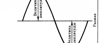
Hello. As I promised in the article Electricity. Basic concepts, in this part we will continue our acquaintance with the basics of electrical engineering, this time we will look at the basic electrical laws.
Let's probably start with the basic law in electrical engineering - Ohm's law , discovered in 1826 by the German physicist Georg Ohm. I think many have heard and know about him, but I’ll still remind you:
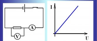
The current strength of a section of an electrical circuit is directly proportional to the voltage applied to this section and inversely proportional to its resistance.
In formula form it looks like this:
Where
I is the current strength passing through a section of the circuit (measured in amperes);
U – voltage on a section of the circuit (measured in volts);
R – resistance of the circuit section (measured in Ohms);
To better remember Ohm's law, it is very convenient to use this triangle:
To find the desired value, close it with your finger and the remaining two will tell you how to find it. If the values are located at the same level, then they need to be multiplied. If the values are located at different levels, then it is necessary to divide the upper parameter by the lower one.
The fundamental law of electrical engineering is Ohm's law
The fundamental law of electrical engineering is undoubtedly Ohm's Law. Named, like most laws of physics, after its discoverer, the German physicist Ohm, it reads:
The current strength of a section of an electrical network is directly proportional to the voltage applied to this section and inversely proportional to its resistance.
In symbolic expression, Ohm's Law looks like this:
I=U÷R, where I is the current strength in the circuit (Ampere), U is the network voltage (Volts), R is the network resistance (Ohm).
In this form, Ohm's law has no practical application in the electrical engineering of residential and industrial buildings. Let me remind you that alternating voltage is used to power buildings and slightly different laws of electrical engineering apply here. But Ohm's law is one of the bases underlying all formulas and all electrical calculations.
The law of the relationship (correspondence) of voltage, current and power in an electrical circuit has practical application. It is derived mathematically from Ohm's law and is based on two algebraic formulas expressing physical laws:
P=U×I, where P is the power of the electrical network (Watt), U is the voltage, I is the current.
I=U÷R, where I is current, U is voltage, R is resistance.
If you sit a little, remember simple algebra and manipulate these two formulas, you can get a hint diagram in which all four quantities are: U; I; R; The P's are mathematically related to each other.
The practical application of these mathematical formulas of electrical laws can be applied in the calculation of a simple 220-volt electrical network without electric motors.
For example: Lighting one room with 20 incandescent light bulbs. The network voltage is constant and equal to 220 volts. The power of each light bulb is 25 watts.
By simple multiplication we get the following results:
Total network power consumption: 25 Watt × 20 light bulbs = 500 Watt.
Network current: 500 watts ÷ 220 volts = 2.3 amperes.
If there are three such rooms in an apartment, then the total operating current in the network will be 3 × 2.3 watts = 6.9 Amperes.
In accordance with this calculation, you can select the rating of the lighting circuit breaker for the entire apartment. We round up 6.9 amperes to the value of the ratings of commercially available machines. This is 10 amps.
Conclusion: A simple calculation according to the basic law of electrical wiring made it possible to calculate the rating of the required circuit breaker.
Serial connection - series circuit
When connecting consumers in series, for example, ordinary light bulbs, the current in each consumer is the same, but the voltage will be different. At each consumer the voltage will drop (decrease).
And Ohm's law in a series circuit will look like:
When connected in series, the consumer resistances add up. Formula for calculating total resistance:
Kirchhoff's laws
The electrical work of any room is carried out in the form of closed, working electrical circuits. The two main laws that determine processes in electrical networks are Kirchhoff's laws. There are two of them. Both of them apply to both direct and alternating currents.
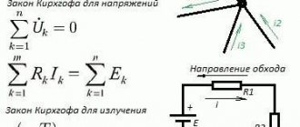
Kirchhoff's first law states:
The total value of currents directed to an electrical network node is equal to the total value of currents directed from the node.
In practice, the operation of Residual Current Devices (RCDs) is based on Kirchhoff's first law. The operation of the RCD is to turn off the power supply to the network when leakage currents occur. During normal operation, the total value of the current flowing into the electrical network is equal to the value of the current flowing out of it. If the equality of currents is violated, then there is a leak in the network. The RCD is designed and connected in such a way that if there is a current leak, the RCD detects it and disconnects the power supply.
Kirchhoff's second law states:
Any closed loop of an alternating electrical network has equal values of complex voltages and EMF (electromotive forces) on all passive elements of the network.
Note: Complex voltage is the value of AC mains voltage.
Practical application can be explained on any apartment power supply group. For clarification, let's look at an apartment.
No matter how many power supply groups there are in the apartment, at any outlet or lamp the voltage in the network (in operating mode) will be 220 volts.
One more basic law of electrical engineering needs to be remembered.
Parallel connection - parallel circuit
With a parallel connection, the same voltage is applied to each consumer, but the current through each of the consumers, if their resistance is different, will be different.
Ohm's law for a parallel circuit consisting of three consumers will look like:
In a parallel connection, the total resistance of the circuit will always be less than the smallest individual resistance. Or they also say that “the resistance will be less than the least.”
The total resistance of a circuit consisting of two consumers in a parallel connection:
The total resistance of a circuit consisting of three consumers in a parallel connection:
For a larger number of consumers, the calculation is made based on the fact that with a parallel connection, the conductivity (the reciprocal of the resistance) is calculated as the sum of the conductivities of each consumer.
Joule-Lenz law
The Joule-Lenz law establishes a connection between the current “running” through a conductor, its resistance and the heat that is released.
In mathematical symbolism, the Joule-Lenz law looks like this:
Q=I2×R×t, where Q is the amount of heat generated in the conductor, in Joules; I is the current strength; R is the resistance of the conductor; t is the time it takes for the current to pass in seconds.
As information: Lenz is a Russian physicist Emilius Christianovich Lenz. Russian physicist, electrical engineer, physical geographer. 1804-1865 years of life.
Speaking about the practical application of the Joule-Lenz law, it is difficult to name in which part of electrics it does not manifest itself. Electric heaters, electric water heaters, thermal curtains, selection of circuit breakers, thermal relays in automation and much more.
Of course, these are not all the basic laws of electricity. In their meaning, these laws are of fundamental importance.
Other articles on the site
- Automatic circuit breakers
- Types of power transmission line supports by material
- Types of supports by purpose
- Overhead power lines with SIP wires
- Wooden supports for overhead power lines
- Reinforced concrete power transmission line supports
- Reinforced concrete power transmission line supports
- Protection of humans from electric shock, direct and indirect contact
- How does a 380 Volt low voltage consumer receive electricity?
- Cable network wells installation stages
Online electrical magazine
OM (named after the German physicist G. Ohm (1787-1854)) is a unit of electronic resistance. Designation Ohm. Ohm is the resistance of a conductor, between the ends of which a voltage of 1 V appears at a current of 1 A. The defining equation for electronic resistance is R = U / I.
Ohm's law is the main law of electrical engineering, which cannot be dispensed with when calculating electronic circuits. The relationship between the voltage drop on a conductor, its resistance and current strength is simply remembered in the form of a triangle, at the tops of which are the signs U, I, R.
To Ohm's law
The most important law of electrical engineering is Ohm's law
THE JOULE-LENZ LAW (named after the British physicist J.P. Joule and the Russian physicist E.H. Lenz) is a law characterizing the thermal effect of electron current.
According to the law, the amount of heat Q (in joules) released in a conductor when a constant electronic current passes through it depends on the current strength I (in amperes), the resistance of the conductor R (in ohms) and the time of its passage t (in seconds) : Q = I2Rt.
The conversion of electronic energy into thermal energy is widely used in electronic furnaces and various electric heating devices. The same effect in electronic machines and devices leads to involuntary energy consumption (energy loss and decreased efficiency). The heat causing these devices to heat up limits their load. When overloaded, an increase in temperature may damage the insulation or shorten the service life of the installation.
KIRCHHOFF'S LAW (named after the German physicist G.R. Kirchhoff (1824-1887)) - two main laws of electronic circuits. The first law establishes the relationship between the sum of currents directed to the connection node (positive) and the sum of currents directed from the node (negative).
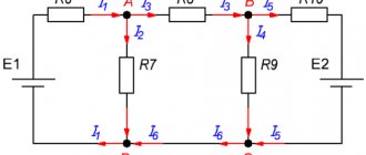
The algebraic sum of the current strengths In converging at any branching point of the conductors (node) is equal to zero, i.e. SUMM(In)= 0. For example, for node A you can write: I1 + I2 = I3 + I4 or I1 + I2 – I3 – I4 = 0.
Current node
The 2nd law establishes the connection between the sum of electromotive forces and the sum of voltage drops across the resistances of a closed circuit of an electronic circuit. Currents that coincide with an arbitrarily chosen direction of bypassing the circuit are considered positive, and those that do not coincide are considered negative.
Current circuit
The algebraic sum of the instantaneous values of the EMF of all voltage sources in any circuit of an electronic circuit is equal to the algebraic sum of the instantaneous values of the voltage drops across all resistances of the same circuit SUMM(En)=SUMM(InRn). By rearranging SUMM(InRn) to the left side of the equation, we obtain SUMM(En) – SUMM(InRn) = 0. The algebraic sum of the instantaneous voltage values on all elements of the closed circuit of the electronic circuit is zero.
THE LAW OF TOTAL CURRENT is one of the main laws of the electric field. Establishes a connection between magnetic force and the amount of current passing through the surface. The total current is understood as the algebraic sum of currents penetrating a surface bounded by a closed loop.
The magnetizing force along a contour is equal to the total current passing through the surface bounded by this contour. In the general case, the field strength in different parts of the magnetic strip can have different values, then the magnetizing force will be equal to the sum of the magnetizing forces of each strip.
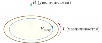
LENZ'S LAW is a basic rule that covers all cases of electrical induction and allows one to determine the direction of the resulting emf. induction.
According to Lenz's law, this direction in all cases is such that the current made by the emerging emf prevents the changes that caused the emergence of the emf. induction. This law is a high-quality formulation of the law of conservation of energy as applied to electrical induction.
LAW OF ELECTRICAL INDUCTION, Faraday's law - a law that establishes a connection between magnetic and electronic phenomena. The emf of electrical induction in a circuit is numerically equal and opposite in sign to the speed of the magnetic flux configuration through the surface limited by this circuit. The magnitude of the EMF field depends on the speed of the magnetic flux configuration.
FARADAY'S LAWS (named after the British physicist M. Faraday (1791-1867)) are the main laws of electrolysis. A connection is established between the amount of electricity passing through an electrically conductive solution (electrolyte) and the amount of substance released on the electrodes when a constant current I is passed through the electrolyte for a second q = It, m = kIt.
Faraday's 2nd law: the chemical equivalents of parts are directly proportional to their chemical equivalents.
GILMET'S RULE - a rule that allows you to find the direction of the magnetic field, depending on the direction of the electron current. When the translational movement of the gimlet coincides with the flowing current, the direction of rotation of its handle shows the direction of the magnetic lines. Or, if the direction of rotation of the gimlet’s hand coincides with the direction of the current in the circuit, the translational movement of the gimlet shows the direction of the magnetic lines penetrating the surface bounded by the circuit.
Gimlet rule
LEFT HAND RULE - a rule that allows you to find the direction of electrical force. If the palm of the left hand is placed so that the vector of magnetic induction enters it (the four extended fingers coincide with the direction of the current), then the thumb of the left hand bent at a right angle indicates the direction of the electric force.
Left hand rule
RIGHT HAND RULE - a rule that allows you to find the direction of the induced emf of electrical induction. The palm of the right hand is positioned so that the magnetic strips fit into it. The thumb bent at a right angle is aligned with the direction of movement of the conductor. The extended four fingers will indicate the direction of the induced emf.
Right hand rule
Recommended files
FREE
Maran Software Engineering
Software engineering
Technical task
Requirements Engineering and Software Specification
-65%
Solving all 30 tickets for the 2021-2022 exam (Theory + Problems)
Physics
FREE
60 tickets + 30 solved problems + theory
Theoretical mechanics
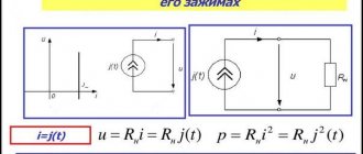
A nonlinear element, such as an incandescent lamp, has a resistance, the value of which increases with increasing voltage, and therefore the current supplied to the lamp.
Electric current
I
is the directional movement of charges that occurs in a closed circuit under the action of
electromotive force
(EMF)
E
of the source (generator).
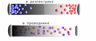
Electric charges are created by the displacement of electrons. When there is an excess of electrons at one point and a deficiency of electrons at another, there is a potential difference between these points. When there is a conductor between the points, a flow of electrons occurs, called current. The positive direction of current is considered to be the direction opposite to the direction of the flow (drift) of electrons and coinciding with the direction of positive charges - holes
(See Electronics Basics section).
If the magnitude of the electric current does not change over time, then it can be defined as the number of electric charges q
, passing through the conductor per unit time
t
, i.e.:
I = q/ t
,
(1 ampere = 1 coulomb/sec; coulomb ≈6.28 ∙1018 electrons). Electric current, the direction and magnitude of which are constant, is called constant
current and can be designated by the capital letter I. Electric current, the magnitude and direction of which does not remain constant, is called
alternating current
.
The value of the alternating current at the considered moment in time is called instantaneous and is denoted by the lowercase letter i
, the instantaneous value of the current
i = dq/ dt
.
When a positive charge moves from one point in the field to another, the electric field does work. The relation of this work is A
to the charge value
q
is called
the voltage
between these points:
U= A/ q
.
The unit of measurement for voltage is Volt [V]. The concept of voltage can also be derived from the quantitative characteristic of the electric field - potential j. The voltage between two points of the electric field is the potential difference at these points (j1 and j2): .
Electrical diagram
is a graphical representation of an electrical circuit that includes symbols of devices and shows the connection of these devices.
In Fig. Figure 2 shows an electrical diagram of a circuit consisting of an energy source - an active element
and
passive elements
: electric lamps 1 and 2, electric motor 3.
Rice. 2
To facilitate analysis, the electrical circuit is replaced with an equivalent circuit
.
Substitution scheme
is a graphical representation of an electrical circuit using ideal elements, the parameters of which are the parameters of the replaced elements.
Figure 3 shows the equivalent circuit of Fig. 2.
Rice. 3
Conductor materials
Conducting materials (aluminum, copper, gold, silver, etc.) have high electrical conductivity. Aluminum is most often used in wires and cables as it is the cheapest. Copper has greater electrical conductivity, but it is more expensive.
Among conductors, a group of materials with high resistivity should be distinguished. These include alloys (nichrome, fechral, etc.) they are used for the manufacture of windings of heating devices and rheostats. Tungsten is used in incandescent lamps. Constantan and manganin are used as resistances in standard instruments.