Theoretical foundations of electrical engineering (TOE) is a required discipline for electricians. First of all, in classes on it, general ideas about electric current, its properties, parameters and main areas of use are studied. Another subject of study is the phenomenon of electromagnetism and how to apply it in practice. Students will learn how to build an electrical circuit, how to perform simple electrical work in an apartment or private house, and how mechanisms that use electricity work.
AC sine wave
1.1. Basic explanations and terms
Electrical engineering
is a field of science and technology that studies electrical and magnetic phenomena and their use for practical purposes of obtaining, converting, transmitting and consuming electrical energy.
Electronics
is a field of science and technology that studies electrical and magnetic phenomena and their use for practical purposes of obtaining, converting, transmitting and consuming information.
Each science has its own terminology. Let's remember the terms and concepts of electrical engineering and electronics.
Electrical circuit
is a set of devices designed for the production, transmission, transformation and use of electric current.
All electrical devices according to their purpose, principle of operation and design can be divided into three large groups.
Energy sources, i.e. devices that produce electric current (generators, thermoelements, photocells, chemical elements).
Electromotive force
- electrical potential difference created by a source of electrical energy (electrochemical element, mechanical generator, thermoelement, photocell, etc.).
Receivers, or load, i.e. devices that consume electric current (electric motors, electric lamps, electrical mechanisms, etc.).
Conductors, as well as various switching equipment (switches, relays, contactors, etc.).
The directed movement of electric charges is called electric current. Electric current can occur in a closed electrical circuit. Electric current, the direction and magnitude of which are constant, is called direct current and is denoted by the capital letter I
.
Electric current, the magnitude and direction of which does not remain constant, is called alternating current. The value of alternating current at the considered moment in time is called instantaneous and is denoted by the lowercase letter i
.
For an electrical circuit to operate, it is necessary to have energy sources. In any source, due to external forces of non-electric origin, an electromotive force is created. A potential difference or voltage arises at the source terminals, under the influence of which an electric current arises in the external part of the circuit connected to the source. There are active and passive circuits, sections and elements of circuits. Active circuits are electrical circuits that contain energy sources, while passive circuits are electrical circuits that do not contain energy sources.
Linear electrical circuit
- this is a circuit in which not a single parameter of the circuit depends on the magnitude or direction of the current or voltage.
Nonlinear electrical circuit
- this is an electrical circuit that contains at least one nonlinear element. The parameters of nonlinear elements depend on the magnitude or direction of current or voltage.
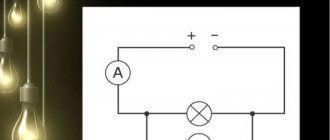
Electrical diagram
is a graphical representation of an electrical circuit that includes symbols of devices and shows the connection of these devices. In Fig. Figure 1.1 shows an electrical diagram of a circuit consisting of an energy source, electric lamps 1 and 2, and electric motor 3.
Rice. 1.1
To facilitate analysis, the electrical circuit is replaced by an equivalent circuit.
Substitution scheme
is a graphical representation of an electrical circuit using ideal elements, the parameters of which are the parameters of the replaced elements.
Figure 1.2 shows the equivalent circuit.
Rice. 1.2
Electrical insulating materials (dielectrics)
Electrical insulating materials (dielectrics) have very low electrical conductivity. They are gaseous, liquid and solid. Solid dielectrics are especially diverse. These include rubber, dry wood, ceramic materials, plastics, cardboard, yarn and other materials. Textolite and getinax are used as structural materials. Textolite is a dielectric material based on fabric impregnated with phenol-formaldehyde resin. Getinax is paper impregnated with phenol-formaldehyde resin.
1.2. Passive equivalent circuit elements
The simplest passive elements of an equivalent circuit are resistance, inductance and capacitance. In a real circuit, not only the rheostat or resistor has electrical resistance, but also conductors, coils, capacitors, etc. A common property of all devices with resistance is the irreversible conversion of electrical energy into thermal energy. The thermal energy released in the resistance is usefully used or dissipated in space. In an equivalent circuit, in all cases where it is necessary to take into account the irreversible transformation of energy, resistance is switched on.
The conductor resistance is determined by the formula
(1.1)
where l is the length of the conductor; S—section; ρ is resistivity.
Conductivity
is the reciprocal of resistance.
Resistance is measured in ohms (Ohm), and conductivity is measured in siemens (Sm).
The resistance of the passive section of the circuit is generally determined by the formula
where P is power consumption; I - current. The resistance in the equivalent circuit is depicted as follows:
Inductance
- this is an ideal equivalent circuit element that characterizes the circuit’s ability to accumulate a magnetic field. It is believed that only inductive coils have inductance. The inductance of other elements of the electrical circuit is neglected.
The inductance of the coil, measured in henry [H], is determined by the formula
where W is the number of coil turns; F is the magnetic flux of the coil excited by current i.
The figure shows an image of inductance in an equivalent circuit.
Capacity
- this is an ideal element of an equivalent circuit that characterizes the ability of a section of an electrical circuit to accumulate an electric field. It is believed that only capacitors have capacitance. The capacitance of the remaining elements of the circuit is neglected.
The capacitance of the capacitor, measured in farads (F), is determined by the formula:
where q is the charge on the capacitor plates; Uc is the voltage across the capacitor.
The figure shows an image of a capacitance in an equivalent circuit
Types of conductors
When studying the theoretical foundations of electrical engineering, one cannot ignore the influence of the conductivity of substances used in various devices on the electric current. Based on this parameter, materials can be divided into the following groups:
- Conductors are substances that easily pass current (metals, electrolytes, liquid mercury, graphite rods). Conductivity can refer not only to the electrons themselves, but also to ions, both positively and negatively charged. An example of the second type is a solution of sodium chloride in water, which has electrolyte properties (pure water is a dielectric).
- Semiconductors are substances that acquire the ability to conduct current only under certain external conditions (temperature, lighting and other factors).
- Dielectrics are materials that do not have the ability to conduct current. Due to this, they have insulating properties.
Dielectric in an external electric field
Active equivalent circuit elements
Any energy source can be represented as an EMF source or a current source. An EMF source is a source characterized by electromotive force and internal resistance. An ideal EMF source is one whose internal resistance is zero.
In Fig. Figure 1.3 shows an EMF source, to the terminals of which a resistance R is connected. Ri is the internal resistance of the EMF source. The EMF arrow is directed from the point of the lowest potential to the point of the highest potential, the voltage arrow at the terminals of the source U12 is directed in the opposite direction from the point with a high potential to a point with a lower potential.
Rice. 1.3
Current
(1.2)
(1.3)
An ideal EMF source has internal resistance Ri = 0, U12 = E. From formula (1.3) it is clear that the voltage at the terminals of a real EMF source decreases with increasing current. In an ideal source, the terminal voltage does not depend on the current and is equal to the electromotive force. Another way to idealize the source is possible: representing it as a current source. A current source is an energy source characterized by an almost constant current value and low internal conductivity.
An ideal current source is one whose internal conductivity is zero and whose resistance is infinity.
Let's divide the left and right sides of equation (1.2) by Ri and get
,
where is the current of the current source;
- internal conductivity.
An ideal current source has gi = 0 and J = I.
The current of an ideal source does not depend on the resistance of the external part of the circuit. It remains constant regardless of the load resistance. A conventional image of a current source is shown in Fig. 1.4.
Any real EMF source can be converted into a current source and vice versa. An energy source whose internal resistance is small compared to the load resistance approaches in its properties an ideal EMF source.
Rice. 1.4
If the internal resistance of the source is large compared to the resistance of the external circuit, it approaches in its properties an ideal current source.
1.4.Basic definitions related to schemes
There are branched and unbranched circuits. In Fig. Figure 1.5 shows an unbranched diagram. In Fig. Figure 1.6 shows a branched circuit containing two EMF sources and 5 resistances. The resistance of the connecting wires is assumed to be zero.
A branch circuit is a complex combination of connections between passive and active elements. In Fig. Figure 1.6 shows a branched circuit containing two EMF sources and 5 resistances. The resistance of the connecting wires is assumed to be zero.
Rice. 1.5
Branch
- this is a section of an electrical circuit through which the same current passes.
node
- this is the junction of three or more branches of an electrical circuit.
A node at which two branches converge is called removable, that is, topologically it is not a node. A topological, real or irreducible node is one in which three or more branches are connected. A node in the diagram is indicated by a dot.
A series connection is a connection of sections of a circuit in which the same current passes through all sections. In a parallel connection, all sections of the circuit are connected to one pair of nodes and are under the same voltage. Any closed path that includes several branches is called a circuit.
Rice. 1.6
Used radio components
When learning the basics of electrical installation, you always become familiar with the main parts used in electronics. All of the listed types of substances are used in their production. Conductor materials are used to make cables that connect devices included in the circuit. They also connect the power supply to the load voltage. The conductors are wound on coils, which are either used independently or used in transformers, electrical machines, and on printed circuit boards (the latter are themselves made of dielectric). Transistor and diode elements include conductor and semiconductor parts made from several types of materials with different levels of conductivity. The main functions of dielectrics are protective and insulating.
1.5. Operating modes of electrical circuits
Depending on the load, the following operating modes are distinguished: nominal, no-load, short-circuit, coordinated mode. In nominal mode, electrical devices operate under the conditions specified in the manufacturer’s data sheets. Under normal conditions, current, voltage, and power values do not exceed the specified values. Idle mode occurs when the circuit is broken or the load resistance is disconnected. The idle mode is an emergency mode for current sources. Short circuit mode occurs when the load resistance is zero. The short circuit current is several times higher than the rated current. Short circuit mode is an emergency for voltage sources. Matched mode is the mode of transmission from the source to the load resistance of the highest power. The matched mode occurs when the load resistance becomes equal to the internal resistance of the source. In this case, maximum power is released into the load.
Security measures
An electrician needs to know electrical labor protection and safety standards. Neglecting them can result in a traumatic situation, disability or death. Basic Rules:
- The handles of the tool must be made of dielectric. The use of non-insulated handles is prohibited.
- Use grounded wristbands when working with microcircuits.
- Do not touch live cables.
- When carrying out work, hang warning posters.
- Use only wires coated with dielectric insulation.
- Wear rubber gloves and special dielectric shoes.
- Testing of network parameters should be carried out only with measuring instruments.
- If one of your colleagues is injured by an electric shock, immediately turn off the current, call a doctor and carry out first aid measures.
Studying the TOE is mandatory for anyone who intends to carry out electrical installation work on their own. First of all, students will learn about the types of electric current and their characteristic features, as well as about devices that use electricity.
Semiconductors
Semiconductors in electrical conductivity occupy an intermediate position between conductors and dielectrics. Simple semiconductor substances - germanium, silicon, selenium, complex semiconductor materials - gallium arsenide, gallium phosphide, etc. In pure semiconductors, the concentration of charge carriers - free electrons and holes is small and these materials do not conduct electric current.
If an impurity (donor or acceptor) is introduced into a semiconductor material, that is, doping is performed, then the semiconductor becomes the owner of either electronic (n) conductivity (excess electrons) or hole (p) conductivity (excess of positive charges - holes). If we connect two semiconductors with different types of conductivity, we get a semiconductor device (diode), which is used to rectify alternating current.
Power in an electrical circuit characterizes the intensity of energy conversion from one type to another per unit time. The unit of power is Watt (W).
For a DC circuit, source power
Pist = E I.
Receiver power
Rpr = U × I = R × I2 = U2/R