In most cases, each house or apartment is initially equipped with standard one-, two-, or three-key switches that control lighting from only one specific location. But this is extremely inconvenient, because how many times have you had to get out of bed to turn on the lighting in the room?
With modern electrical installations, pass-through switches have become more often used, which can turn off or turn on, for example, the lighting in a room at the entrance to the room and at the same time near the bed or, for example, on both sides of the corridor. How to do this? Very simple! To do this, it will be enough just to read this article.
What is a pass-through switch
A pass-through switch is a switch with several groups of contacts that is capable of simultaneously controlling a light source from several places. In the modern market of electrical installation materials, this device is represented by the following types:
- single-key with one input and 2 outputs;
- two-key with two inputs and 4 outputs;
- three-key with three inputs and 6 outputs;
- cross with two inputs and two outputs for controlling lighting from more than 3 places.
This type of device can be either a keyboard or touch or remote (control from a remote control). In most cases, standard key switches are used, however, in the case of installing a Smart Home system, it is better to install remote pass-through switches, which are controlled using a remote control or a special application for a smartphone.
How does a switch with two keys work?
The equipment has a total of 12 contacts, 6 for each double switch (2 inputs, 4 outputs), therefore, to connect equipment of this type, you need to take 3 wires for each key of the device.
Switch diagram:
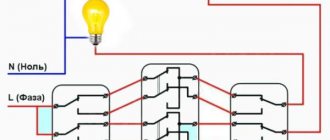
Switch circuit
- the device consists of a pair of independent contacts;
- The upper contacts of the device N1 and N2 are switched to the lower ones by pressing the keys. The elements are connected by a jumper;
- the second contact of the right switch, shown in the diagram, is in phase;
- the contacts of the left mechanism do not intersect with each other, joining two different sources;
- 4 cross contacts are combined in pairs.
The two-key switch is installed as follows:
- A pair of double mechanisms are installed in socket boxes in selected areas.
- For each light source, a separate three-core cable is placed in the socket box, the cores of which are cleared of insulation by about 1 centimeter.
- In the diagram, the cable cores are designated as L (phase), N (working zero), ground (protective).
- The device is equipped with markings, which simplifies the task of connecting wires to the switch terminals. The cores are connected to the terminals in pairs.
- The bundle of wires is carefully placed in the socket box, after which the switch mechanism, frame and cover of the protective housing are installed.
What the marking looks like:
Two-key switch markings
Connection diagram example:
Connection diagrams
To make the work process easier, it is recommended to select wires of a certain light. There is color coding of wires for Russia and other CIS countries. Also, a beginner can learn to distinguish cables from it. According to Russian markings, yellow and green colors are used for “ground”; the neutral cable is usually marked with blue. The phase may be red, black or grey.
Video - Connection diagram for a two-key pass-through and crossover switch from two or more places
Three-key equipment diagram
When installing a triple device, intermediate (cross) switches are used, which are connected between the two side elements.
Three-key equipment diagram
This switch is equipped with two inputs and outputs. The cross element can transfer both contacts at the same time.
Triple equipment assembly process:
- Ground and zero are connected to the light source.
- The phase is connected to the input of one of a pair of pass-through structures (with three inputs).
- The free wire of the light source is connected to the input of the other switch.
- The two outputs of one element, which has three contacts, are combined with the input of a cross device (with two pairs of outputs).
- The two outputs of the pair mechanism (with three contacts) are combined with the other pair of terminals of the next switch (with four inputs).
Video - How to connect a 3-key switch
Operating principle of a pass-through switch
In appearance, pass-through switches are identical to standard ones, but due to their design, their operating principle is significantly different.
So, when you press the key of a regular switch, the circuit simply closes or opens, but if you press the key of a pass-through switch, it opens one group of contacts and closes another.
Important! Unlike standard two-key (single-key) devices, pass-through switches can only work in pairs, since one and the second control the phase supply to the lighting device and if one of them is not in the circuit, then the phase wire will not flow to the lighting source, as a result the light will not light up.
Let us next consider what the connection diagram for a pass-through switch from 2 places should be, since this is considered the most common option for implementing lighting systems in houses, apartments or offices.
Device and types
ordinary
How to correctly define a pass-through switch? Essentially, these are two switching devices that control one lighting fixture (or group).
If you look at a walk-through two-key household switch, then outwardly it is absolutely no different from an ordinary device. It also consists of a working part (contact group) and a protective housing (frame and keys). And its main functions are the same - to break or close an electrical circuit.
But it will never be possible to make a pass-through switch from a regular switch; the second one has a more complex connection diagram. An ordinary two-key switch has three contacts - one incoming (the phase from the supply network is supplied to it) and two outgoing (the phase wires of the lamps must be connected to them). The pass-through model has six contacts.
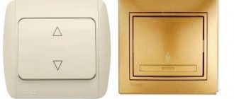
with backlight
If you press a button on an ordinary device, a closed circuit is created between the voltage source and the lamp, resulting in lighting. The pass-through version has an internal movable contact (change-over), when you press a key, it simultaneously opens one circuit and closes the second, that is, it switches from one terminal to another. In this case, the second circuit is the contacts of the paired switch, because the pass-through switching device does not work as an independent device.
sensory
When choosing a pass-through switch model, please note that in addition to key models, there are also touch models. They are more expensive, so be guided by your financial capabilities.
Backlit models are considered very convenient to use; you won’t have to look for such a device for a long time in a dark room. Each key has a luminous window indicating the location of the switch.
Connection diagram for pass-through electrical switches for lighting control from 2 places
The connection diagram of the pass-through switch allows you to effectively control the lighting from 2 points when turning the lighting on and off:
- on a flight of stairs in a cottage;
- in a long corridor;
- in office premises;
- in walk-through rooms;
- in the bedroom (controlling the lighting circuits near the bed and at the entrance to the bedroom) and so on.
To answer the question: “how to connect a 2-key pass-through switch?” you need to understand the principle of its operation. Let's do this using the example of the photo presented above.
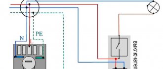
In this circuit, the neutral conductor (in most cases blue) from the distribution box is connected directly to the light source (light bulb). The phase wire (brown) from the distribution box comes to the 1st contact of pass-through switch No. 1, after which it goes from the first contact of switch No. 2 to the second end of the light bulb.
In this case, jumpers must be installed between contacts No. 2 and No. 2, as well as contacts No. 3 and No. 3 of pass-through switches No. 1 and No. 2 (these jumpers are connected in the junction box).
Thanks to these jumpers, the phase to the lighting source can be supplied from either one or a second switch, which will allow you to turn on the lighting from several places.
This is considered the simplest scheme because it allows you to control only one light source. In order, for example, to turn on the LED backlight and the main lighting separately, you need to use a two-key pass-through switch, the operating principle of which you will find in the next section.
Purpose of the changeover switch
Reversible equipment is installed because of its durability and ease of use.
Reversible devices are used:
- in multi-storey buildings (on stairwells of entrances, in multi-storey cottages);
- at different ends of long corridors of apartments and hotels (if it is necessary to turn on the light when entering the room, and turn it off when leaving);
- in the bedrooms (by the bed and by the front door);
- in passages (in the metro);
- in basements;
- in areas with a large area (in sports complexes, hospitals, auditoriums, assembly halls).
Example of use in the photo below:
Example of using a changeover switch
Control circuit for two-key pass-through switch
The principle of operation and connection diagram of a two-key pass-through switch is similar to a single-key switch, however, unlike the previous ones, these devices allow you to control lighting in several groups.
Let's consider the principle of operation of these devices according to the following photo:
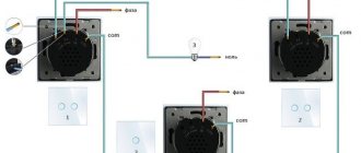
This circuit contains:
- two double pass-through switches;
- power supply 220 V (phase and neutral);
- distribution box in which switching is performed;
- 2 groups of lighting circuits (for example, this could be a chandelier and LED lighting in a hall or room).
In this scheme, “0” (with correct blue color switching) is connected directly from the distribution box to one output of the 1st and 2nd lighting groups. Next, the phase wire (brown) comes into the distribution box and comes out of it and is connected to outputs No. 1 and No. 2 of pass-through switch No. 1.
Next, the outputs from pass-through switch No. 1 with numbers No. 3, 4, 5, 6 go into the distribution box, in which they are connected with similar outputs No. 3, 4, 5, 6. Then from outputs No. 1 and No. 2 of pass-through switch No. 2 the phase goes to the 1st and 2nd lighting groups and is connected to the second contact.
How to install in a junction box
In order for a double pass-through switch or lighting devices to perform their function for many years, the switching process must be approached thoroughly.
Often, due to negligence or lack of extensive experience in performing electrical work, twists can be found in junction boxes. However, this is a serious violation, since over time, contact may be lost in these twists, as a result of which the wires will begin to heat up, burn out, and a fire will occur. It is also strictly forbidden to connect copper and aluminum wires without any interlayer.
For reliable connection of cables and wires in junction boxes, 3 methods are recommended:
- Soldering contacts.
- Welding of conductors using special transformers.
- Connecting conductors using special clamps (WAGO).
Basic recommendations for installing two-key pass-through switches
When installing both standard and two-key pass-through switches, it is recommended:
- The placement height from the floor level should be 90 cm.
- The distance from the door or window opening to the pass-through switch must be at least 15 cm.
- Distribution boxes with switching must be located in a visible place and at the same time they must be placed at a distance of 15–30 cm from the ceiling level.
- For installation of pass-through switches, it is recommended to use a 3-core flexible cable with a cross-section of 1.5 mm² (VVGng, PVSng, ShVVP, and so on).
- Cable and wire products must be laid in corrugation, in grooves or cable channels.
- All metal surfaces of lamps must be grounded.
Basic mistakes when connecting changeover equipment
- A common mistake when installing a pass-through device is incorrectly connecting the wires to the terminals;
- use of a cable with a small cross-section (it is recommended to use a 1.5 mm2 cable);
- It happens that when installing equipment, the wires are connected incorrectly (the phase must be connected to the contact of the first switch, and the second cable of the lighting device to the zero of the junction box);
- you need to be careful when selecting wires for switches (2 keys - three-wire, 3 keys - four-wire);
- Beginners make the mistake of thinking that the common terminal is the one that contains one contact. It is necessary to check the equipment with a tester screwdriver before connecting the cable.
When installing electrical wiring and installing structural elements, you must remember safety rules. Before starting work, it is important to turn off the voltage in the electrical panel. It is not recommended to touch the contacts with bare hands, even when the current is turned off; when installing devices, use only special tools.
conclusions
Pass-through single-key and two-key switches are modern switches that allow you to organize control of one or more lighting sources from different places in one or adjacent rooms.
As can be seen from the above information and photos, we can say that despite the design (single-key or pass-through two-key switch, the connection diagram for 2 sources) is very easy to install and allows you to effectively control the lighting in a huge cottage, a large retail space or in industrial buildings.
To connect these devices it will be enough:
- two pass-through switches with 2 keys or two single-key switches;
- distribution box;
- flexible cable with three cores.