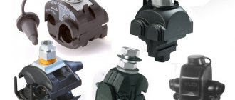
Scope of application of piercing clamps and their characteristics
These devices allow you to quickly connect to the main line, while ensuring the necessary connection conditions. A characteristic feature of such clamps is that during the installation process there is no need to remove the insulation from the SIP, which significantly speeds up the process and makes it as safe as possible.
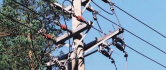
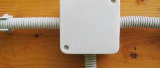
Connection using a waterproof clamp of SIP wires
The main area of application of these devices is supplying power to the consumer's distribution panel, for example, connecting a house or garage to the main trunk line. The clamp body is made of durable plastic that is resistant to ultraviolet radiation and other harmful environmental influences. The contact point itself is reliably protected from moisture. Relatively low cost, easy installation and dismantling and full compliance with regulatory requirements have made this connection method almost standard. The barbaric option for connecting to the main line - “twisting” – is now almost never seen.
Twisting is not only an unreliable, but also an unsafe connection method
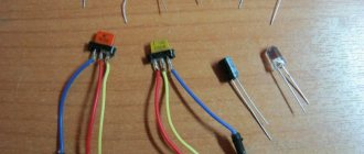
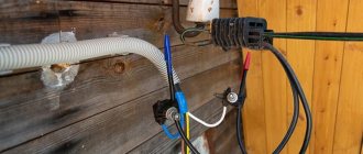
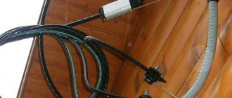
Connection of SIP with VVG cable
When introducing an electrical line into a structure, VVG cable or another similar brand of copper conductor is most often used. Direct contact of copper and aluminum conductors during installation is extremely undesirable. In this case, increased resistance to electric current occurs at the junction, which leads to overheating of the conductors, accelerated corrosion and destruction. Breaking the contact can lead to various negative consequences, including a fire. To prevent this from happening, special methods should be used to separate copper and aluminum conductors from each other.
The simplest of them is to connect a copper and aluminum core using a threaded connection. For this option you will need a steel bolt with a nut of suitable diameter, several simple washers and one engraving washer. Installation of such a connection is very simple: a washer is installed between dissimilar conductors to prevent direct contact of copper with aluminum. It is advisable to choose washers coated with pure tin or solder based on it. After tightening the bolt, the connection must be wrapped with insulating tape. This method is very simple, but extremely unreliable, so it is practically not used.
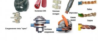
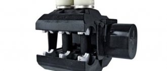
For a better and more reliable connection of SIP with copper cable, completely different methods are used, which are performed using specially designed connecting elements, such as piercing clamps, monolithic aluminum-copper sleeves and branching clamps. Let's consider each option separately.
- Piercing clamps. With this method, the insulation from the cores of the connected cables is not removed. A copper and aluminum conductor with an insulating layer is inserted into the corresponding hole in the clamp, after which the entire structure is tightened with a threaded connection. Tightening can be done either with one top bolt or with separate bots for each core of the connected cables. The body of the piercing clamp is made of durable polymer material with glass fiber reinforcement. It provides reliable protection to the connection from the effects of negative environmental factors.
- Branching compressions. Among experts they are called “nuts”. These connecting elements have in their design three bimetallic plates and tightening bolts, which are enclosed in a protective housing. To connect SIP to copper cable, you need to remove the insulation from the cores, insert it between the plates and secure with bolts. The use of clamps is more preferable for aluminum cores of self-supporting wires, since they are very sensitive to the notches that arise from the spikes of piercing clamps.
- Bimetallic sleeves. These connecting elements are made of copper and aluminum parts combined into one monolithic structure. The connection of dissimilar cores is carried out by crimping. The conductors are stripped and inserted into a sleeve, which is crimped with a special tool, thereby creating reliable contact. The connection point is sealed with a special heat-shrinkable tube filled with an insulating gel. Under the influence of high temperature, the tube contracts and reliably protects the contact from the negative influence of the external environment.
An alternative to all of the above methods of connecting self-supporting insulated wires with VVG copper cable or other brands is the direct insertion of self-supporting insulated wires into the building with a connection to the electrical panel. The rules of the PUE and the requirements of energy supply organizations do not prohibit this option, as it reduces the possibility of electricity theft.
Important! For wooden and other structures that can burn, the installation of self-supporting insulation insulation is prohibited by the rules of the Electrical Installation Rules. In this case, it is necessary to make a transition from a self-supporting cable to a copper cable such as VVG or any other suitable design.
List of main characteristics
The characteristics of clamps of this type are determined by the following parameters:
- The number of branch SIPs that connect to the main core (usually from one to four).
- Cross-section of the main core (mm2).
- SIP cross-section (mm2).
- Maximum current load (A).
- Product weight (g).
As an example, we give a table of characteristics of NILED connecting fittings.
Characteristics of NILED connection clamps
Piercing clamps for Vulture wires: operating principle
To describe how this device works, we give an example of its design.
Design of a piercing clamp for SIP
Designations:
- A – tightening bolt.
- B – sealed housing.
- C – eye for SIP.
- D – eyelet for the main conductor.
- E – cap, placed on the end of the SIP to ensure insulation.
- F – contact pad for the main core.
- G – gear-shaped contacts for SIP.
During the connection process, the bolt is tightened; under its pressure, the gear contact knives (G) cut through the SIP insulation and ensure reliable contact. At the same time, the contact pad (F) ensures adhesion to the main core. Please note that the design of the tightening mechanism is designed in such a way as to prevent bursting. That is, the bolt “breaks” when the threshold force is reached.
Branch piercing clamps for SIP
Such clamps for SIP, such as branch, insulated, with the ability to pierce the insulation, are used for:
1. Connections of wires of one highway or several highways.
2. Making branches from highways.
3. Connections of street lighting to highways.
4. Connecting SIP with bare wire.
5. Connecting SIP with cables.
The industry produces several different models of clamps with the ability to work in different conditions.
Single bolt piercing branch clamp (bare SIP)
Refers to those clamps that are absolutely protected from moisture. Used to remove uninsulated trunk cables to self-supporting insulated wires. The cross section of such a cable is from 16 to 95 mm. The clamp body is made using a polymer that is resistant to weather changes and ultraviolet wave radiation. It is glass reinforced with a fixing bar.
The piercing clamp uses a corrosion-resistant aluminum alloy. Clamp tightening bolt
galvanized by galvanizing, the mechanism is steel, also galvanized. The clamp connection area is filled with antioxidant lubricant.
Single-bolt branch piercing clamp (SIP-SIP)
The clamp is protected from the negative effects of moisture and is used for removal from main insulated cables to self-supporting insulated wires. The cross section of such a wire is 16-95 mm2.
For the manufacture of such a body, glass-reinforced polymer is also used. The case is resistant to atmospheric agents and ultraviolet rays; there is a bar at the bottom for locking with a key.
The piercing clamp is made of aluminum alloy, resistant to corrosion. The tightening bolt and steel spring are galvanized. The clamp connections are filled with antioxidant lubricant.
Two-bolt branch piercing clamp (bare-SIP)
The clamp is made in a waterproof design and is used to remove the bare wires of the main line to the SIP. The cross section of such cables can be 16-96 mm2.
For the manufacture of the body, glass-reinforced polymer is used, resistant to weather changes and ultraviolet rays. At the bottom of the case there is a bar for fixing with a key.
The piercing clamp is made of a special aluminum alloy that is resistant to corrosion. The tightening bolts and steel springs are galvanized. The clamp connections are also filled with a lubricant containing an antioxidant.
Two-bolt branch piercing clamp (SIP-SIP)
The clamp is also made in a waterproof housing and is used for removal from main self-supporting insulated wires. The cross-section of the diameter of such wires can be 16-95 mm2.
The body is made from glass-reinforced polymer, which is resistant to weather changes and ultraviolet rays. At the bottom of the case there is a bar for fixing with a key.
The piercing clamp is made of aluminum alloy, resistant to corrosion. Bolts for tightening clamps and steel springs are galvanized. The clamp connection points are also filled with a lubricant that resists oxidation.
Two-bolt branch piercing clamp (SIP-SIP)
The clamp is also made in a waterproof housing and is used to make a tap from the main insulated aluminum wires. The cross-section of such cables can be 50-120 mm2 to SIP with a cable of 25-70 mm2.
The body is also made of glass-reinforced polymer material, resistant to changes in atmospheric conditions and ultraviolet radiation. At the bottom of the case there is a bar for fastening with a key.
The piercing clamp is made of corrosion-resistant aluminum. The bolts for tightening the clamps and steel springs are also galvanized.
Execution options
Piercing connecting fittings are produced in two versions, depending on the functional purpose. Let's talk briefly about each of them.
A device for connecting bare and insulated wires. The design (see Fig. 4) and operating principle were described above. The main purpose is to connect SIP to power conductors or the main grounding line.
Clamps for connecting SIPs to each other. The design feature of such devices is that the contacts on both eyes have teeth that pierce the insulation. Accordingly, two bolts are used for tightening. The operating principle of the clamp is the same as the previous version. The appearance of the device is shown below.
Piercing clamp for SIP-SIP connection
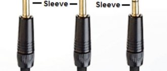
Connection of SIP with copper cable
This type of connection is used very often. You will definitely encounter it in the following situations: when introducing a copper cable into the house, which must be connected to a self-supporting wire, and when connecting SIP to copper contacts inside the distribution board. Connecting SIP to the copper busbars of the electrical panel is very simple. For this operation, it is necessary to use special tips or washers that prevent contact of aluminum with copper. Of course, tips are technically a more correct option. They are made of two parts, aluminum and copper, fused into one monolithic product.
Installation of piercing clamps
The algorithm for organizing a tap using a piercing clamp is quite simple, but there are several nuances that need to be paid attention to:
- As a rule, devices of this type are designed in such a way that installation work can be carried out without turning off the power supply. That is, the tightening mechanism is isolated from the contact area. But, nevertheless, the electrician performing the connection must have the appropriate clearance group.
- To separate the core, special devices (separating wedges) should be used.
Separating wedges
You cannot use other available tools for this purpose, for example, a screwdriver, since there is a high probability of damaging the insulation. Two wedges should be installed with an interval of 20.0-25.0 cm, which allows you to separate the core from the bundle at a distance of 4-6 cm, this is quite enough for work. If possible, you can loosen the support clamp.
- The fittings are suitable for aluminum and copper conductors. It is also an ideal adapter, preventing the formation of a galvanic couple.
- It is prohibited to connect two or more self-supporting insulation insulation systems to one fitting, unless the design requires this. This prohibition is due to the fact that proper reliability and tightness of the contact will not be ensured.
- Clamps must not be reused. There are several reasons for this:
- It is impossible to determine the required clamping force, since the mechanism is “broken,” which threatens to compress the SIP above the breaking force threshold.
- the contact teeth are deformed during crimping. Consequently, when reused, they may no longer pierce the insulating coating or provide the required contact area.
- The teeth of the new clamp have a special coating in the form of silicone grease, which ensures sealing of the cut insulation. A previously used device will no longer have such lubrication; therefore, moisture will get under the insulation.
- It is imperative to put on the cut of the connected SIP the sealed cap that comes with the clamp. There are models with built-in cut sealing. Such devices are preferable, since individual parts tend to get lost; in addition, when working at height, it is inconvenient to reach into a bag every time for a sealed tip.
- To tighten the connecting fittings, use spanners (13 or 17, depending on the design of the clamp) with an insulating coating.
Dielectric spanners
Having dealt with the nuances, let's move on to the procedure:
- Lightly “release” the tightening bolt. This must be done in order not to damage the insulating coating.
- The core and SIP are inserted into the eyes intended for them. In this case, it is necessary to ensure that the cables are clearly in the middle of the clamping contacts. After this, the bolt must be tightened by hand, thereby securing the electrical wires.
- Holding the clamp from the bottom, the bolt is tightened using a spanner wrench (usually 13).
- You need to tighten it until the bolt “breaks”. This indicates that the required clamping force has been achieved.