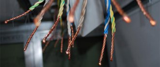
Electrical busbars are used in high-voltage and low-voltage power plants of various types and applications. Without these devices it is impossible to imagine the assembly and installation of an electrical circuit in an enterprise. Busbars act as current conductors, connecting installation elements without energy loss. Thanks to them, it is possible to optimize the operation of the chain, reduce material costs and make installation of equipment much easier. Also, when using tires, the electrical installation becomes smaller in size.
As a rule, conductive busbars are elongated metal plates of different shapes. Depending on the area of use, there are several types of these devices. In the article we will talk about them in detail.
To make equipment maintenance easier, you need high-quality tires
BUS TERMINAL CONNECTIONS
1. The terminals of electrical devices according to GOST 21242 can be flat and pin. Terminal dimensions are given in Appendix 9.
2. Welded connections of busbars with terminals made of homogeneous metals must be carried out in accordance with the instructions given in section 3.
The welded connection of busbars made of aluminum and its alloys with a copper terminal should be performed using a copper-aluminum adapter plate.
3. Demountable connections of busbars with flat terminals, depending on the material of the terminals, busbars and climatic factors of the external environment, must be carried out using one of the methods specified in paragraphs. 1.2 - 1.7.
4. For group A, contact connections of busbars with pin terminals, depending on the busbar material and the value of the rated output current, should be made:
a) for busbars made of copper, steel and aluminum alloy - directly with steel nuts1 (Fig. 1 a);
1 In all cases, thrust nuts made of copper or brass must be used
b) for aluminum busbars with output to a rated current of up to 630 A - directly with nuts made of copper and its alloys in accordance with GOST 5916 (Fig. 2.1 b); for rated current above 630 A * directly with steel or copper nuts with a protective metal coating on the working surface of the bus (Fig. 2.1 c) or using adapter copper-aluminum plates according to GOST 19357 (Fig. 2.1 d), or adapter plates made of aluminum alloy (Fig. 2.1 d).
Rice. 2.1. Pin Connection
1 - output from copper or its alloys; 2 - steel nut; 3 - copper busbar, made of aluminum alloy or steel; 4 - nut made of copper or its alloys; 5 — aluminum or aluminum alloy tire; 6 — metal coating or EPS-98 lubricant; 7 - copper-aluminum plate; 8 - aluminum alloy plate; 9 - aluminum alloy tire
2.5. For group B, contact connections of busbars with pin terminals, depending on the material of the busbars, should be made:
a) copper busbars - directly with steel nuts (Fig. 2.1 a);
b) tires made of aluminum and aluminum alloy - using adapter copper-aluminum plates in accordance with GOST 19357 (Fig. 2.1 d) or adapter plates made of aluminum alloy (Fig. 2.1 d), while the adapter plates made of aluminum alloy must have a protective metal coating or EPS-98 lubricant must be applied.
2.6. The dimensions of the holes in the tires must correspond to the diameter of the pin:
| Pin diameter, mm | 6 | 8 | 10 | 12 | 16 | 20 | 24 | 30 | 33 | 36 |
| Tire hole diameter, mm | 6,6 | 9 | 11 | 14 | 18 | 22 | 26 | 32 | 35 | 39 |
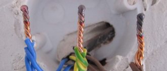
Conductor designation
The grounding conductor is marked PE. It is always indicated in yellow-green color. The colors run in longitudinal lines. Moreover, the use of these two colors separately is prohibited by GOST. For the neutral and middle conductor (working) marked N, blue color is used.
When connecting neutral protective and working conductors, combine all three colors. The marking in this case looks like PEN. The conductor is blue, and at its end and at the connection points there is a yellow-green stripe. Currently, it is also possible to use the opposite color: a yellow-green conductor with a blue stripe at the end.
CONNECTIONS OF FLEXIBLE BUSBARS BETWEEN THEM AND WITH TERMINALS IN OPEN DISTRIBUTION DEVICES
3.1. Connections and branches on copper, steel, aluminum and steel-aluminum flexible busbars of open switchgears should be made by crimping, crimping, using loop or branch bolt clamps. Branches of aluminum and steel-aluminum busbars should preferably be performed by propane-oxygen welding. Terminations should be made using hardware clamps1 connected to the flexible busbar by crimping2, bolts or welding.
1 See Technopromexport catalog “Fittings for overhead power lines and open switchgears”, Moscow, 1975
2 Methods for crimping clamps with a hydraulic tool (press PGE-20, PGR-20M1, Technos, etc.) are given in the “Instructions for connecting wire and cable cores”; crimping with a powder press is in Appendix 10.
3.2. Bolt loop and branch clamps for aluminum and steel-aluminum busbars must be made of aluminum alloys, for copper - from brass, for steel - from steel (Fig. 3.1, 3.2).
Rice. 3.1. Loop clamp 1 - clamping bar; 2 — clamp; 3 - bolt; 4 - nut; 5 - spring washer
Rice. 3.2. Branch clamp
1 - base; 2 — clamp; 3 - bolt; 4 - nut; 5 - spring washer
Bolt loop clamps intended for connecting copper busbars to aluminum must have tinned copper grooves soldered into them at the manufacturer's factory.
3.3. Bolted hardware clamps are designed for tightening tires using dies (Fig. 3.3). For copper busbars they should be made of brass, for aluminum busbars - from aluminum alloys.
Rice. 3.3. Hardware bolted clamps
a - for connection to a rod terminal and a flat one having one hole; b, c - for connection to flat terminals with two and four holes
The design of hardware clamps intended for aluminum busbars includes adapter copper plates connected to the clamp body by soldering or welding. These plates provide better contact when connecting an aluminum hardware clamp to a copper terminal on a device or to a copper-clad or copper-reinforced aluminum terminal.
If the aluminum hardware clamp is connected to the aluminum terminal by bolting or welding, the copper plates should be removed.
Hardware clamps have one, two or four holes for connection to device terminals or buses.
3.4. Hardware clamps that have one hole in the claw with a diameter of 14.5 mm can be drilled to the diameter of the pin terminal, but not more than 30 mm.
3.5. The bars should be secured in the clamp in the following order:
— place the busbar in the corresponding grooves of the clamp (when installing adapter clamps from copper to aluminum, the copper busbar should be in contact with the tinned copper groove, and the aluminum busbar with the aluminum one);
— install dies;
— coat the cut part of the bolts with AMC-1 grease, avoiding its contact with the contact surface;
- tighten the bolts.
The bolts must be tightened with nuts so that all parts of the clamp experience equal pressure along the length of the contact. After the bolts are fully tightened, there should be a gap of 3 - 4 mm between the dies. The proximity of the dies closely indicates that the dimensions of the grooves do not correspond to the given tire and the required pressure in the contact is not provided. Such clamps must be replaced.
3.6. The termination of flexible busbars with hardware clamps for connection to flat terminals of devices should be done in accordance with the design of the terminal.
3.7. Flexible busbars, bewitched by hardware clamps, are connected to the flat terminals of the devices directly.
3.8. Connections of flexible busbars to the pin terminals of devices should be made:
a) copper, terminated with a hardware clamp with one hole, with a terminal diameter of up to 28 mm - directly; for output diameters over 28 mm - through copper plates; with two and four holes - through copper plates;
b) aluminum and steel-aluminium, terminated with hardware clamps - through copper plates.
Definition
Electrical connecting busbars allow you to combine all elements of an electrical installation into one whole. Essentially, these are conductors whose resistance is low.
When several busbars are combined at one point, they speak of busbar trunking. As a rule, they are installed on insulators, which also serve as supports. It is hidden in a special box (channel). Thanks to this, it is protected from environmental factors. The busbar must always be resistant to dynamic and thermal loads and shock current from the electrical network.
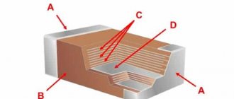
Electric buses are made in several designs. To divide them into types, several classifications are provided.
According to the method of execution, flexible and rigid tires are distinguished. They are also called flat and tubular. Flexible tires do not twist. They should not have a high degree of gravity. Moreover, the degree of tension of all wires should be the same. The length of the tire may change under the influence of temperature. Therefore, rigid models are equipped with flexible jumpers that should compensate for these changes. In addition, they are equipped with vibration dampers.
In addition, electrical buses can be insulated or non-insulated. Already from the name it is clear that in the first case the tire has an insulation layer, but in the second it does not.
Annex 1
Bolts and nuts
| Bolt length | Weight 1000 pcs. (steel), kg. with thread diameter, mm | |||||
| M6 | M8 | M10 | M12 | M16 | M20 | |
| Hex head bolts, GOST 7798 | ||||||
| 16 | 5,930 | 11,80 | 22,70 | 32,57 | — | — |
| 20 | 6,742 | 13,25 | 24,97 | 35,85 | 68,49 | — |
| 25 | 7,871 | 15,07 | 27,82 | 39,95 | 75,87 | 136,4 |
| 30 | 8,981 | 17,35 | 30,66 | 44,05 | 83,24 | 147,9 |
| 32 | 9,426 | 18,140 | 32,03 | 45,68 | 86,19 | 152,5 |
| 35 | 10,090 | 19,32 | 33,88 | 48,43 | 90,62 | 159,4 |
| 40 | 11,200 | 21,30 | 36,96 | 52,87 | 97,99 | 170,9 |
| 45 | 12,310 | 23,27 | 40,05 | 57,31 | 105,70 | 182,5 |
| 50 | 13,42 | 25,25 | 43,13 | 61,76 | 113,60 | 194,0 |
| 55 | 14,53 | 27,22 | 46,22 | 66,20 | 121,50 | 206,8 |
| 60 | 15,64 | 29,200 | 49,30 | 70,64 | 129,40 | 219,1 |
| 65 | 16,76 | 31,170 | 52,39 | 75,08 | 137,30 | 231,5 |
| 70 | 17,87 | 33,14 | 55,47 | 79,53 | 145,20 | 249,8 |
| 75 | 18,98 | 35,12 | 58,56 | 83,97 | 153,10 | 258,1 |
| 80 | 20,09 | 37,69 | 61,64 | 88,42 | 161.00 | 268,1 |
| 85 | 21,20 | 39,07 | 64,73 | 92,86 | 168,90 | 280,8 |
| 90 | 22,31 | 41,04 | 67,81 | 97,29 | 176,80 | 293,2 |
| 95 | — | 43,02 | 70,80 | 101,70 | 184,70 | 305,5 |
| 100 | — | 44,99 | 73,98 | 106,20 | 192,60 | 317,8 |
| Hex nuts of normal accuracy (GOST 5915) | ||||||
| — | — | 9,65 | 16,31 | 30,08 | 59,90 | 117,1 |
| Hex nuts, low, normal accuracy (GOST 5916) | ||||||
| 0,948 | 4,011 | 8,478 | 10,610 | 19,58 | 34,68 | |
Note
To determine the mass of bolts and nuts made of aluminum alloy and brass, the mass indicated in the table should be multiplied by 0.359 for aluminum alloys and by 1.083 for brass.
Features of an electrical panel for a garage
The type of panel used for installation in a garage is slightly different from an apartment panel, but there are some features that must be taken into account:
The body of the shield used for the dacha is of the overhead type. To carry out welding work when repairing a car, it is necessary to install in the panel one automatic machine rated at 50 A and a meter with a current winding. Sockets installed in the electrical panel must be grounded. A charger is additionally installed in the shield to recharge the batteries. To ensure safe operation, the shield is equipped with toggle switches:
- at high voltage – SA 1-4;
- at low voltage – SA 5-7.
Diodes VD-1-4 are installed for reverse voltage. When using three-phase current, a switch is installed.
Choice. The electrical panel for the garage must be equipped with a charger and a switch for three-phase current.
The use of electrical panels reliably protects all devices from environmental influences and mechanical damage, and also allows you to use electrical devices while observing safety precautions.
Appendix 2
Washers (GOST 11371)
| Bolts | Washers | |||
| Diameter, mm | Diameter, mm | Thickness, mm | Weight of steel washers 1000 pcs., kg | |
| interior | outer | |||
| 6 | 6,4 | 12,5 | 1, | 0,853 |
| 8 | 8,4 | 17,5 | 1,6 | 2,320 |
| 10 | 10,5 | 21,0 | 2,0 | 4.080 |
| 12 | 13,0 | 24,0 | 2,5 | 6,270 |
| 16 | 17,0 | 30,0 | 3,0 | 11,300 |
| 20 | 21,0 | 37,0 | 4,0 | 32,900 |
Washers (GOST 6958)
| Bolts | Washers | |||
| Diameter, mm | Diameter, mm | Thickness, mm | Weight of steel washers 1000 pcs., kg | |
| interior | outer | |||
| 6 | 6,4 | 18,0 | 1,6 | 2,79 |
| 8 | 8,4 | 24,0 | 2,0 | 6,23 |
| 10 | 10,5 | 30,0 | 3,0 | 14,60 |
| 12 | 13,0 | 36,0 | 3,0 | 20,80 |
| 16 | 17,0 | 48,0 | 4,0 | 49,60 |
| 20 | 21,0 | 60,0 | 5,0 | 97,40 |
Note
To determine the mass of washers made of aluminum alloy and brass, the mass indicated in the table should be multiplied by: 0.356 for aluminum alloy, 1.083 for brass.
Letter marking
The letter designation will help you read the diagram correctly and determine the type of bus or wire. Like colors, letters have their own meaning.
Electrical wires and tires with alternating current are deciphered as follows:
- L – single-phase network conductor.
- L with numbers 1, 2 or 3 – conductor in a three-phase network.
- N – neutral conductor (or neutral).
- M – middle conductor.
- PE – grounding conductor (protective).
- PEN – combined neutral conductors (protective and working).
With direct current, the designations will look like this:
- L+ – positive (or positive) conductor.
- L- – negative (or negative) conductor.
All these markings and designations are mandatory. They are regulated by accepted regulations.
It’s difficult to remember all this at once. But an experienced electrician knows all this. This marking will allow you to determine where and what is connected. And this will be enough for an ordinary person to understand, for example, what kind of tire is needed for electric machines. It may be needed when repairing electrical wiring in the house. It’s easy to connect additional sources to it later.
Source
Appendix 9
The terminals of contact electrical devices are flat and pin (GOST 21242)
1. Dimensions of flat terminals
Table P9.1
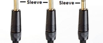
Pin sizes (threads)
| Rated current, A, before switching on | Terminal material1) | ||
| Steel | Brass | Copper | |
| Tensile strength, 107 Pa | |||
| 50 | 32 | 25 | |
| 2,5 — 8,3 | M3 | M3 | — |
| 16 | M4 | M4 | — |
| 25 | M5 | M5 | — |
| 40 | MB | M6 | — |
| 63 | — | M6 | — |
| 100 | — | M8 | — |
| 160 | — | M10 | — |
| 250 | — | M12 | M10 |
| 320 | — | M16 | M12 |
| 400 | — | M20 | M 16 |
| 630 | — | — | M20×1.5 |
| 800 | — | — | M24×2.0 |
| 1000 | — | — | M30×2.0 |
| 1250 | — | — | M33×2.0 |
| 1600 | — | — | M36×2.0 |
| 2000 | — | M42×3.0 | |
| 2500 | — | — | M48×3.0 |
| 3200 | — | — | M56×4.0 |
1) It is permissible to use other materials that ensure reliable contact.
Marking for three-phase alternating current
“Hints”, which are expressed in the color and letter designation of tires and wires, will help you identify the elements of electrical installations. They are not chosen randomly. They are regulated by standards.
There are two ways to color code tires. The first implies that the marking of electrical busbars is applied at the manufacturing stage. The manufacturer uses insulation of different colors. The second is suitable in cases where the product has one color. In such situations, colored electrical tape is used to mark different phases.
In the case of three-phase current, the marking will look like this:
- Phase “A” turns yellow.
- Phase “B” is colored green.
- Phase “C” is colored red.
What are they?
According to the section configuration
The G-type is a “G” shaped rail where one curved end is shorter and lower than the opposite edge. It is rare to find such a profile on the domestic market, since it is designed for installation of equipment of European standards.
The C-type is symmetrical and more common. The edges of the rail are equally curved, which provides reliable fixation for terminal blocks and clamps of other devices.
Omega-type has a completely different cross-section, similar to the Greek letter “omega”: the ends of the bar are sharply bent in both directions from the rail, forming peculiar “ears”. This design is adapted to almost all electrical elements and devices.
According to the presence of holes for fastenings
Perforated ones have holes approximately every centimeter, which greatly simplifies the process of installing the slats.
- according to the material of manufacture:
- made of aluminum;
- made of stainless steel (more common).
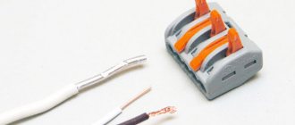
Connection
Installing and connecting the cross-module is not difficult. The case is simply mounted on a DIN rail, so it can be installed very quickly. Switching wires is also easy. The video below shows how to connect a crossover module, and also clearly demonstrates the advantage of using it:
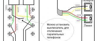
Connection diagram
Advantage of installation
So we looked at what a cross-module is, why it is needed and what sizes this product comes in. Finally, we recommend buying a modular distribution block from trusted manufacturers: ABB, IEK, Legrand, Dekraft or Schneider Electric. The quality of materials plays a very important role in the operation of this device.
We also recommend reading:
- How to assemble a distribution board
- What types of DIN rails are there?
- Connection diagrams for a three-phase electricity meter
Advantages and disadvantages
First, let's talk about the advantages of the connecting bus for circuit breakers. So, the comb has the following advantages when installing electrical wiring:
- Better connection of switching equipment. If the connection of jumpers is represented by two ends of the wire in one terminal, then the use of a comb bus reduces this value by 2 times, which is positively reflected in the quality of the contact.
- As we have already said, the connecting comb for milking machines can withstand up to 63 A. Make a cable from wire with a cross-section of 16 mm2. it will be much more difficult.
- Wiring in the switchboard using a distribution bus looks neater, as can be seen in the photo below:
As for the disadvantages, they are as follows:
- It is not always possible to connect machines from different manufacturers. The fact is that different companies can produce modular switching products of different heights. As a result, the tap does not always reach the smaller AV connector.
- More problematic is replacing the circuit breakers in the panel. To replace one device, you will have to loosen the connecting bus on all connectors, otherwise you won’t be able to raise it higher, and without this you won’t be able to get the machine.
- If there is a need to add another AV to the panel, you will have to either change the comb completely or connect it with a jumper, which will negatively affect the aesthetic appearance of the electrical panel. In addition, when replacing, you will have to turn off the voltage on all supply lines, which is sometimes very undesirable, especially in production.
By the way, the comb connecting bus can be used to connect not only circuit breakers, but also RCDs, as well as automatic circuit breakers. We will tell you later how to connect this connector in the panel.