Many daily processes require precise timing, both starting and finishing on time. An example is cooking food or the sequence and timing of various chemical reactions.
Technical devices are no exception. Their timely activation and termination of work is the beginning and end of the automation processes of any production or service. Control of stopping and starting the operation of equipment in such cases is carried out using a time relay.
Application area
A time relay is a device designed to turn on/off devices and control processes at a certain period of time.
Such equipment is quite often used in industry to control production processes without human intervention. Relays are no less often used in everyday life. It can be used for systematic watering, turning on lighting at certain times, etc.
Electronic microprocessor time relay model PCR-513 can be programmed by the user
Liquid crystal display
LCD Display Data
At the top of the display: days of the week MO - Monday; TU - Tuesday; WE—environment; TH - Thursday; FR - Friday; SA - Saturday; SU - Sunday. The day of the week is set with the D+ button. In the middle part of the display: current and programmable time. The time is set with the , H+ and M+ buttons. In the lower left part of the display: numbers of on and off cycles ON - on; OFF - disabled; numbers from 1 to 16 - cycle number. Cycles are configured using the button in the lower right part of the display: control mode ON - constantly on; AUTO - automatic mode; OFF - permanently disabled. The control mode is set using the MANUAL button
Types and classification
Devices such as time relays are divided into:
- block;
- modular;
- built-in
Block ones differ in the specific installation process, which requires individual power supply from the network. Built-in ones do not require a separate power supply, as they are most often used as auxiliary elements in more complex circuits. Modular time relays are also not connected to a separate power line. Modular relays are mounted on a DIN rail.
Time relays can also be:
- electromagnetic;
- pneumatic;
- electronic;
- motor.
Electronic or electromagnetic relays are mainly used for household use. This is explained by the fact that they are as efficient as possible, and their cost is low and affordable for any consumer.
Design features
Like any device of this type, the electronic timer TE 15 consists of the following structural elements:
- small-sized switching power supply
- microprocessor and its electronics
- information LCD display
- interface control unit (buttons for programming)
- relay connecting or disconnecting the load
- battery (needed to save settings if the power is turned off)
The presence of a programmable microprocessor allows you to set eight different program cycles that will control the load. This is done using the buttons installed on the front panel (Fig. 3).
Rice. 3 Control unit buttons
The information display can operate in two modes: display the current time and be used to set operating modes.
Advantages and disadvantages of the device
Electronic relays have the advantage that they perform their functions with high precision. The only negative quality that can be noted is that they require precision in programming; the time interval that can be set is significantly less than that of electromechanical ones. It is also worth noting the fairly high cost.
The main advantages of electromagnetic relays are their low price; they do not require constant maintenance, regular programming, or changing settings. The disadvantage of such devices is their limited service life, as well as not very good operation with direct current.
Time relays on the modern market are presented in a wide variety of types and models
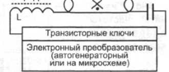
On transistors
The transistor circuit is the easiest to assemble and the least expensive of all the options. The simplest one includes only 8 elements that can be placed without a board by soldering together. Often such a simple time relay is created and used for lighting: after pressing the toggle switch, the lamp lights up for a specified period of time, then turns off itself.
What you will need:
- e/m relay 250 V, 5 A, higher parameters are allowed;
- transistor KT973A, similar ones, for example, 973B, are also suitable;
- diode KD105B or other suitable;
- microswitch (“mikrik”, button or with a slider);
- resistors 3 pcs.: 100 Ohm; 2.2 mOhm and variable at 820 Ohm (it will regulate the time pause);
- capacitor 3300 uF, 25 V.
The homemade product can be used, for example, to turn on ventilation in the garage.
Work algorithm:
- Switching starting position S1 - “off”. Capacitor C1 is still discharged and when the first element is switched to another position, its charging starts.
- Trans. VT1 is still open because the charged C1 current flows through its base. When charging, it decreases and VT1 comes out of saturation after a short period of time (from the state when the emitter-collector resistance is the lowest, the composite transistors do not seem to enter saturation).
- The collector current VT1 drops faster; at the moment there is not enough of it for the executive release K1 to keep the contacts K1.1 closed, they are released.
- To restart the relay, move the switch to the “off” position so that the capacitor is discharged and after 5-10 seconds. - “on” The duration of the delay depends on the capacitance of this element (the higher it is, the longer the pause) and on the position of the trimmer resistor R1 (the resistance increases - the longer the pause). Diode VD1 is designed to protect trans. VT1.
Final look:
Simple assembly on one bipolar transistor
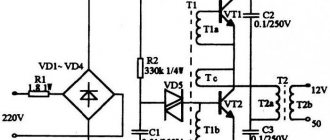
Spare parts for 12 volt turn off delay relay:
- e/m release 10 A, 250 V;
- capacitor 3.3 mF, 25 V;
- diode KD105B (or analogue);
- resistors: 1 kOhm; from 1 to 100 Ohms, in our case 18 Ohms;
- switch.
Using a multimeter we determine the diode leads:
Determine the resistance of the relay winding. The ratio of supply voltage to it must not exceed max. current on the collector Ikmax of the applied trans. (KT315 Ikmax=100 mA=0.1 A).
We check the transistor with a multimeter:
Next, a homemade 12 V time relay is designed according to the following diagram:
Assembly step by step in illustrations:
Here are other similar extremely simple schemes (the first has a delay from 2 seconds to 9 minutes 20 seconds):
How does it work
The algorithm for the first scheme we described (it is also similar to the others analyzed in the section):
- Switch S1 in charging position - con. C1 stores energy through resistor R1 (the number of ohms should not be too low).
- When C1 is “full,” the “micrik” is switched to “on.” - it begins to discharge through resistor R2 and transistor base VT1.
- While the discharge is in progress, the relay contacts are closed. When the current becomes weak enough, they open.
Elementary effective option with a delay of 10 minutes
The option considered below is regarded by users as one of the best among simple homemade products of this type.
Delay - 10 min. You can do without paying. Adjustment - standard resist. R1, control the product with contacts. You can also create a platform, the layout below:
With two transistors, also for switching loads
There are 2 transistors in the circuit:
- the first (B1) - adjustment, pause control. Starts a timer;
- the second is an electronic key, activating and turning off the power of the device being serviced.
The difficulty lies in selecting resistance R3. We will need such that the relay closes only when a pulse arrives from B2. Reverse activation of the load occurs only when B1 is triggered; this parameter must be selected experimentally.
Principle of operation
The operating principle of a time relay is as follows.
Since these are devices that count time, each of them has a timer that is set for a certain period. Therefore, it is necessary to set the timer for the required on or off time. The timer is built into the front of the device. Depending on the specified characteristics, this device will turn off the power supply and turn it on at a certain time. This cycle will continue until the relay is switched to rest.
A time relay, regardless of its design and characteristics, can be set from one second to 999 hours.
ABOUT NEW DEVELOPMENTS
During the operation of the TE-15 device, a number of shortcomings were revealed, one of which, as noted, was a temporary malfunction of the LCD display.
Therefore, in order to increase operational reliability and improve the existing device, EKF began to supply models of new digital timers such as TE-80 and TE-80-24-230. These models, like the TE-15, belong to the PROxima line, but they have improved characteristics.
In later models, the number of programs available to the user has increased significantly. For example, they already remember up to 40 on/off cycles.
The introduced additional pulse operating mode allows you to double the number of operating cycles. In addition, for example, the cost of the TE-80 device model does not differ from the cost of the TE-15.
Thanks to the increased display size and more convenient buttons, it has become much easier to program and operate the device. Additionally, the electronic timer TE-80-24-230 has the ability to operate from a 24 V DC source.
Also, offline storage of information is provided in TE-80 for up to three years, and in TE-80-24-230 for up to 10 years.
Conclusion
Thus, in recent years, the time relay fleet has undergone significant changes. Electronic digital timers have replaced outdated electromechanical devices.
Devices built on the basis of microprocessor technology have a number of advantages and wide possibilities for connection and operation.
Flexible configuration, simple programming, small size and ease of load switching allow the use of electronic timers to control various types of technological equipment. They have become an integral part in both industry and the domestic sector.
PS Everyone is subject to their own individual train of thought, so if you have any questions, additions, clarifications or wishes, be sure to leave them in the comments. I will try to answer and dot all the “i’s” together.
PPS The main tool for making money online and not only is a computer. How to give it reliability, making it fast and immortal, and also speed up its operation up to 30 times is given in the following newsletter: barabyn.ru/wp/computer.
Specifications
All devices that are used in the electrical network must have their characteristics consistent with its parameters, that is, the conditions under which their operation will be stable must be met.
Regardless of the type and specific model, time relays are characterized by the following parameters:
- the voltage at which this device will operate stably;
- switching current, which determines the control current of the device;
- wear resistance, determined by the number of switches on or off and is more suitable for electromagnetic relays;
- type of protection;
- number of contacts;
- device power, indicating the maximum load this device can switch without connecting a contactor.
Based on these data, you can select a device with the required characteristics for certain parameters of the serviced electrical network.
Generator autostart unit
As an automatic input of a reserve, we will consider in more detail the BAZG-1 device, which is a generator autostart unit. With its help, remote control is provided that does not require the presence of people. The main function of the unit is to start and stop the power plant engine. There are five attempts to start, including 5 seconds for the start itself, and 15 seconds for a break between starts with automatic control of the air damper.
The BAZG-1 unit is part of the automatic backup power supply system. An external source issues a command that starts and subsequently controls the operation of the engine. In order for the system to work fully, you will need a shield that switches to reserve.
The BAZG-1 device can work in conjunction with an inverter, which provides starting of the generator and further recharging of the battery. The generator starts and stops by closing and opening two contacts. If the startup attempt is unsuccessful, the unit goes into emergency mode. To exit it, you need to remove power from the unit or cancel the start command. The generator cools down for 30 seconds before shutting down the engine completely.
How to read labels
When labeling such devices, manufacturers try to simplify readability as much as possible. The manufacturer and model of the device are initially indicated on the case. The voltage suitable for normal operation of the device is also indicated. In most cases it is 220 V.
It is also marked for what magnitude and type of current (direct or alternating) the device is suitable for operation. The appliance must also indicate the maximum load current for the particular appliance.
Almost all time relays have terminal markings and a designation for zero and phase connections.
Do-it-yourself homemade electrical contact pressure gauge
Hello! Many people know firsthand about such a measuring device as a pressure gauge. But many people find it difficult to imagine the device and the principle of its operation.
A pressure gauge is designed to measure the pressure of a liquid or gas. Moreover, the pressure gauge for measuring gas and liquid pressure is not structurally different from each other. So if you have a pressure gauge lying around somewhere to measure liquid pressure, then you can safely use it to measure gas pressure and vice versa.
Design and principle of operation of the pressure gauge
To better understand how the pressure gauge works and works, look at the figure below.
The pressure gauge consists of a body with a measurement scale, a copper flat tube 1 folded in the shape of a circle, a fitting 2, a transmission mechanism 3 from the tube to the pointer 4. Using the fitting, the pressure gauge is wrapped in a vessel where the pressure of the medium (gas or liquid) is to be measured.
How does a pressure gauge work?
When gas and liquid under pressure are supplied through fitting 2, the folded tube 1 will tend to straighten, and through the transmission mechanism the movement of the tube will be transmitted to the arrow 4. It, in turn, will indicate the amount of pressure, which can be read using a scale. When the pressure decreases, the tube will collapse again and the arrow will indicate a decrease in pressure.
Electric contact pressure gauge device
I think you can guess how an electric contact pressure gauge works. Its design is no different from a conventional pressure gauge, except that it has built-in contacts. There are usually two of them and their position on the pressure gauge scale can be changed.
What if you don’t have an electrical contact pressure gauge, but you really need one? What to do then? Then you need to make a homemade electric contact pressure gauge.
I'll tell you how to make a homemade electric contact pressure gauge. To do this, you will need a simple pressure gauge, two small strips of tin from a tin can, double-sided tape and two thin wires.
Using a sharp awl, pry up and remove the large retaining ring. Then remove the glass and then the rubber washer. Drill two holes in the pressure gauge housing to allow two wires to pass through them.
Cut two strips from tin and bend them in the shape of the letter L. Solder a thin insulated wire to the base. From double-sided tape, cut two strips equal in size to the strips and stick it on the strips. Next, glue the resulting contacts to the pressure gauge scale within the specified pressure limits.
Pass the wires through the holes and bring them out.
Reinstall the rubber gasket and then the glass. Secure everything with a locking ring. That's it, the homemade electric contact pressure gauge is ready. For example, I used this in a homemade automatic water supply system for a private house.
Connection diagram for electrical contact pressure gauge
In order for this pressure gauge to influence any actuator, a special circuit is needed. You can see an example of this scheme in the figure below.
At a minimum pressure of the medium (gas or liquid) in the electric contact pressure gauge, contacts 1 and 2 will be closed. In this case, the electromagnetic relay K1 will operate. It, in turn, with its contacts K1.1 will supply power to the winding of the magnetic starter K3. Using contacts K3.1, it will bypass contacts K1.1, and when the contacts in pressure gauge 1 and 2 open, relay K1 will release its contacts K1.1. But at the same time, the starter winding K3 will continue to flow around with current. With its contacts K3.2, the magnetic starter will supply power to the motor M of the pump or compressor.
With a further increase in pressure in the pressure gauge, contacts 1 and 3 close. At the same time, the electromagnetic relay K2 will operate and with its contacts will open the power circuit of the coil K3 of the magnetic starter. Contacts K3.2 will open and the power supply to motor M will disappear. With a further decrease in pressure and the closure of pressure gauge contacts 1 and 2, the cycle will repeat.
Manufacturer analysis
Timing relays are manufactured by many manufacturers with factories located throughout the world. The table below shows the most popular models in our country, indicating the manufacturers and type of device mounting.
| Model | Manufacturer country | Company name | Fastening |
| RVTs-10/D | Ukraine | UKR RELAY | DIN rail |
| TR4N 4CO | Poland | Relpol | DIN rail |
| TM M1 | Italy | LOVATO Electric | DIN rail |
| IO 1080/IO | Italy | Perry | DIN rail |
| LT4H-AC240VS | Malaysia | Panasonic | To panel |
Time relay connection diagrams
No complex circuits are used to connect the time relay. When installing it, it is important to know what load it will switch.
This circuit allows you to perform various operations by turning on/off the relay in normal mode
The connection diagram presented above is used in most cases for home use. This scheme ensures stable operation of the device. The only drawback is that the time relay can only be connected to one line with a small load. For example, street lighting or watering the lawn.
Connection diagram of a time relay to a network with electrical appliances with a significant load
A circuit with a contactor is used in cases where it is necessary to disconnect a more powerful load. Its use in everyday life can also be often found. In it, the role of a switching device for a more powerful load is played by a contactor. Such a circuit can control, for example, the operation of an asynchronous motor. It is also used if it is necessary to switch a more powerful load using a low-power time relay.
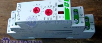
Connection diagram of an ERF-09 time relay to a three-phase network via a contactor
The time relay can also be connected in a three-phase network. The diagram presented above clearly demonstrates this. It is used in places with three-phase voltage. The main switching device is a contactor, which is controlled by a time relay.
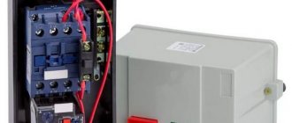
Magnetic starter design
The picture below shows the components of a typical starter. The stationary lower part, when the coil is connected to the power supply, forms an electromagnetic field that attracts the moving element. The contacts connected to the armature close the operating circuit. If the winding is de-energized, the spring will return the system to its original state.
Main functional elements of the starter
The core of the electromagnet is assembled from plates in the shape of the letter “W”. A large number of components block parasitic currents (skin effect). The number of turns is selected taking into account the supply voltage.
Sectors with designations
Explanatory inscriptions on the body are divided into three groups:
- general information and scope (AS1-4);
- information about permissible currents in load circuits (conversion to kW or reverse is performed taking into account the mains voltage);
- graphic designation of contact groups (the broken line indicates synchronous switching).
Each area can be explored in detail. To familiarize yourself with the classification by purpose categories, follow the standards of GOST R 50030.4.1.-2002. The designation AC1 indicates the possibility of connecting the starter to heating elements, incandescent lamps and other loads with weakly expressed reactive characteristics. If you need to ensure the start of a powerful engine, choose a model of the AC3 category.
Contact attachment
This part is mounted on a 220V electromagnetic starter to expand the basic functions:
- activation of reverse engine mode;
- additional load management;
- turning on the light indication.
For your information. A typical attachment mechanism contains two pairs of contacts. Rigid fixation of the block in a certain place is ensured by the special shape of the protrusions of the docking platform. When choosing the appropriate model, you should take into account the compliance with the starter, as well as the normally closed/open state of the contact group.
Contact groups of starters
According to current standards, input and output terminals are marked with the Latin letters L and T, respectively. In reality, taking turns doesn't matter. You can connect paired contacts to the power source and load in any combination. This is the main difference from a relay, where a permanent connection is created with one of the power supply circuits.
Important! It is recommended to follow standard standards so as not to complicate troubleshooting in the circuit and installation work. A separate contact group (13H0, 14H0) is designed for the operation of an independent “pickup” circuit. In this mode, the push-button start is activated by pressing once without holding
In this mode, the push-button start is activated by pressing once without holding
A separate contact group (13H0, 14H0) is designed for the operation of an independent “pickup” circuit. In this mode, the push-button start is activated by pressing once without holding.
Stop button
The control circuit of any starter is organized using two buttons without fixing the on position. “Stop” is indicated in red to enhance safety. In an emergency, this clear identification speeds up the disconnection of the power source.
Starter connection diagram
In the initial position of the “Stop” button, the circuit is closed. When pressed, the induction coil is disconnected from the current source. The electromagnetic field disappears. The spring returns the armature to its original state while simultaneously opening the main contact group. The secondary closure of the circuit in this section does not matter, since the general break is provided by the “Start” button.
For your information. It should be emphasized that modern starters are compact. Such products are suitable for mounting on a standard DIN rail.
Start button
This control element is produced in black (green) color. In the initial state, the contacts are open. Pressing activates the formation of a magnetic field and the movement of the main contact group. “Self-recovery” ensures the functionality of the working power circuit after the start button is returned to its initial position.
Step-by-step installation instructions
In order to independently connect a time relay, you need to decide on which network the installation will take place. It can be single-phase or three-phase. You also need to know in advance what this device will switch, that is, what load needs to be turned off or on.
Based on this data, you need to purchase a device with the required characteristics, or any available one, but you also need to purchase a contactor complete with it.
Tip No. 1: Before installing the time relay, it is necessary to de-energize the entire electrical network for safe work. This is done using an input machine.
The time relay is installed after the electricity meter. At the next stage, using the device’s passport data, it is necessary to determine where its input and output are. The input is the terminals to which you want to connect the wire. Output - these are the terminals from which the switching voltage will come out.
16A continuous pulse time relay is often used in households
Tip #2: Before installation, you also need to check the device for functionality. This must be done before the power goes out.
To do this, you need to connect a cord with a plug to the device according to a given diagram and set the minimum response time. Using a tester, the presence of voltage is checked at the output contacts.
Before connecting, the time relay must be installed securely. Most of these devices are mounted on a DIN rail. After installation, connection is made. The tension of the bolts should be maximum, since if the contact is poor, the device will heat up and can quickly fail, or even worse, it can cause a fire.
Types of motion sensors
To classify devices, we define two main factors: the presence and type of sensor device, as well as installation features.
The main element in the circuit breaker under consideration is a motion sensor. There are several varieties of it, based on different physical laws.
In all cases, the result is the same: when an object appears in the controlled area, the sensor is triggered and the contacts of the circuit supplying the lighting devices are closed.
The most common motion sensor is infrared - it does not emit anything, is relatively cheap and can be installed not only indoors, but also outdoors
Motion sensors for automatically turning on and off lights are:
- Acoustic.
- Infrared.
- Ultrasonic.
- Microwave.
The first two categories of sensors belong to passive devices; they do not emit anything. The detectors of the two remaining varieties are active devices. These options send waves of various lengths into the room, and by the nature of their reflection they determine the presence or absence of new objects in their coverage area.
Equipment of the “active” class with an emitter and receiver is more expensive than “passive” models. The devices are more complex in design, but have a low level of false alarms. Passive devices in this regard are much inferior to their active counterparts, but are cheaper than their competitors.
Acoustic sensors are triggered by the sounds of doors opening, the clicking of heels, and simply sharp claps. This option is best taken for corridors of public buildings.
It is also ideal as an addition to other sensors, so that the light can be turned on by clapping your hands. It is not recommended to install it alone in a private house. There will be too many false reactions to various sharp sounds.
Infrared sensors are designed to be triggered by human heat. But they also react to animals and heated radiators. They must be carefully configured, and the coverage area must be set so that radiators do not fall into it. This is the simplest, most durable and cheapest touch sensor for automatic light control.
Operating principle of ultrasonic sensors. Ultrasonic and microwave sensors are similar in operating principle, they only have a different range of emitted waves
Sensors operating by emitting microwaves and ultrasound are not recommended for installation in residential premises. A person is not able to feel their impact, but it is there, but there is definitely no benefit from it. It has been noticed that domestic animals often react to this radiation in a sharply negative manner.
Such emitters are more suitable for parking lots or open areas. At the same time, active motion sensors also have a limited range.
When organizing control over a large area of ultrasonic devices, you will have to install a lot. Plus, many of them only work during sudden movements. A slowly walking person may completely “fall out” of their field of action.
The ideal option is a combined sensor with several methods of detecting people entering the controlled area. It is more reliable and less likely to trigger erroneously. However, you will have to pay a lot for this accuracy, since such sensors are obviously more expensive than conventional analogs.
Installation errors
The main mistake is connecting a time relay to devices with too much load, for example, an electric boiler. To control the heater, it is necessary to connect a relay through a magnetic starter connected to the boiler.
Also, no less often, time relays are installed in rooms with climatic conditions that are not suitable for normal operation of the device. The temperature should be in the range of -20 - 50°C with a humidity not exceeding 80%.
- Installing a magnetic starter (diagram)
- What is a power limiter (application)
- UZM-3-63 protection device and connection diagram
- How to choose a circuit breaker by power, current, pole
- Installing a power limiter (diagram)
A little history
Previously, a mechanical timer was popular. Built into an outlet, it could turn on household appliances for a certain time (see Fig. 2). In essence, it was a countdown timer; accordingly, its scope of application was limited.
Rice. 2 Kitchen timer - Lemanso LM671 socket
In fact, this is an ordinary socket with a timer; the peak of popularity of such devices occurred in the mid-80s of the last century. Time passed, gradually mechanical devices replaced electromechanical ones, which, in turn, were replaced by electronic ones, such as an electronic stopwatch. The functionality of these devices has expanded significantly. Now it's the turn of digital devices.
Let's return to the topic of the article.