Advantages and disadvantages
The main advantages of this method of laying electrical cables include:
- Increased level of safety compared to installing wiring in the wall. Any accidental damage to the line associated with driving in nails, dowels and other fasteners, which is accompanied by the use of a drill, jackhammer or grinder, is excluded.
- The total amount of cable required to organize the network is reduced. A lot more wires are required to run in the wall.
- You don't have to be a qualified specialist to handle the task yourself. Difficulties can arise only when placing the cable inside a corrugated or metal pipe.
- The junction boxes are located near the wall or at the bottom, which eliminates the possibility of cable breakage.
- There is no need to chisel the walls, apply a thick layer of plaster or perform other finishing work.
Installing wires on the floor allows you to get rid of wall slitting.
Floor wiring scares people for the following reasons:
- Serious difficulties when performing repair work or when it is necessary to replace the electrical cable. Sooner or later the chain may break. It is almost impossible to find the emergency area on your own, so you will have to dismantle the system and lay a new wire. However, the problem can be avoided if you follow the rules and recommendations for installing floor wiring. For example, you should make sure that the cable placed in the pipe moves freely through it. Before pulling out the cable, tie a strong rope or wire to the far end so that you can then easily pull the new wire into the pipe.
- The cost of the work increases due to the need to purchase corrugation, which is not needed when installing in walls, when the cable is hidden inside the groove or under a thick layer of plaster.
With floor installation, replacement becomes more complicated and the cost of work increases
. There are only two disadvantages, but the first is easily eliminated if you follow the installation technology flawlessly.
The final stage of installation
Once you have ensured that the cable has not been damaged during installation, the trench can be backfilled. All laid communications should be covered with sand. Its layer, as at the bottom of the trench, should be 15 cm. The sand, according to the scheme described above, is first moistened with water and then compacted. After this, the trench is simply filled with soil to half the remaining depth. Now you need to place a special signal tape in it. It will serve as an additional signal that a cable is laid below.
Laying warning tape in a trench
It is especially important to lay such a tape when laying it around the territory of a private house. It will protect the gasket from accidental excavations, which are most possible in this situation. After this, the remaining soil is poured into the trench and compacted.
Requirements and standards of the PUE
Laying cables in the floor is officially permitted by the 7th edition of the PUE and refers to hidden wiring. In Chapter 2.1 of these rules it is noted that when forming cable routes, they can be used
- round pipes, boxes of various types with a rectangular cross-section, as well as flexible metal or other fireproof hoses;
- it is possible to lay it directly in the structure of the building structure in a groove formed for this purpose, followed by coating with putty or plaster;
- It is permissible to lay wires into the structure of the structure under a layer of concrete directly at the factory during its manufacture.
To connect wires, you can use crimping, screw clamps of various types, and soldering. In places where the splice is formed, an installation supply of cable should be provided, sufficient to make at least one additional connection. According to the requirements of paragraph 2.1.23, the connection points must be accessible, allowing repair or maintenance to be carried out. Further, paragraph 2.1.24 puts forward the requirement that there are no mechanical impacts on the connection areas.
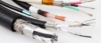
Installation can be carried out using either a flexible multi-wire cable or a rigid single-wire cable. The conductors themselves can be either copper or aluminum. The minimum cross-section depends on the material, connection method and design. When connecting with screw terminals, the minimum cross-section of copper wire is 1 mm², increasing to 2 mm² when switching to aluminum. Copper conductors can also be connected by soldering with a minimum cross-section of 0.5 mm² for a single-wire conductor and 0.35 mm² for a multi-wire conductor. The exact cross-sectional value is determined by calculating the consumer’s power at the project execution stage.
It is separately indicated that when installed in a channel, regardless of its design, it must be possible to replace the electrical wiring if such a need arises.
Communication cable laying standards
Requirements for laying communication cables depend on several criteria, which include, among other things: the installation method (in the ground or in the air), climatic conditions in the region, the type and characteristics of the cable products used.
Rules and regulations for laying communication cables in the ground
The communication cable can be laid in the ground by trenching (the trench is dug before installation) and trenchless methods (using cable-laying equipment). In soils of categories I, II and III (unless the standard design for laying communication cables provides otherwise), trenchless installation is always used. The same applies to category IV soils, provided that soil digging is carried out 2–3 times. If the use of cable-laying mechanization equipment in the area is complicated (for example, rocky terrain), the use of drilling and blasting equipment is permissible.
1.2. Laying depth
The rules for laying communication cables (optical and electrical, armored and unarmored) provide for the following values of installation depth in soils of categories I–IV:
• 1.2 m for trunk, trunk connecting and optical intrazonal cable communication lines (MKLS/MSKLS/VZKLS, respectively). • 0.9 m - electric cables of VZKLS lines of wire broadcasting class I. • 0.8 m - electric cables of primary networks outside populated areas (0.7 m when laid in populated areas), as well as wire broadcast lines of class II.
The standards for laying communication cables in soils of category V and higher determine the following values of masonry depth (the requirements are also valid for soils of category IV developed by drilling and blasting equipment):
• 0.5 m - for all types of cables, provided that rock reaches the surface to a height of up to 0.4 m. • 0.7 m - all types of cables if there is a soil layer above the rock up to 0.6 m thick. In this case The communication cable is buried in the rock to a depth of 0.5 m. If the thickness of the soil layer is more than 0.7 m and less than 1.3 m, the cable is not buried in the rock, but is laid above it at a distance of 0.1 m.
The depth of laying cable lines in permafrost soils and soils with deep freezing is carried out in accordance with the requirements of SNiP for laying communication cables, design and construction of foundations for buildings and structures in permafrost areas (SNiP II-15-74 and SNiP II-18-76).
1.3. Recommendations for laying communication cables in trenches
Laying a communication cable (PUE 2.3.83) in a pre-developed trench involves the construction of a cushion in its lower part and an upper covering layer of sandy soil 10 cm thick. According to clause 2.3.86 of the PUE, joint laying of communication and power cables is permissible in one trench when maintaining a distance of 500 mm between them. Cables of wired broadcasting lines can also be laid together, provided that they have the same performance class (the distance between them is also 500 mm). At the same time, it is not recommended to lay more than 6 cables in one trench (unless the standard design for laying communication cables does not contain special requirements with justifications for the decisions made).
When crossing cable lines with railway tracks or highways, the communication cable is laid in pipes with a diameter of 100 mm, made of polyethylene or asbestos cement. The same requirement is valid for laying single-pair cables for service stations and wired broadcast networks.
When constructing trenches in soils with high water levels and when laying pipes above the depth of seasonal soil freezing, additional measures must be taken to protect cables, given in the “Instructions for protecting communication cables from being crushed by ice in a flooded cable duct of the Russian Ministry of Communications.”
The laying of cable lines through areas with stray currents (for example, electrified tram tracks) is carried out in accordance with the current GOST for laying communication cables (GOST 67-78).
Norms and rules for laying communication cables in cable ducts and manifolds
The rules for laying cables in sewers are different for different types of cables. Optical cables are laid, as a rule, in free channels in the amount of 5–6 units. If electrical cables are already laid in the channel, the “optics” are laid in a polyethylene pipe (or without it if the cable is armored with an additional protective sheath).
Requirements for laying certain types of subscriber communication cables in sewers:
• KM-4, KMA-4: laying only in a free channel. Cables with an outer diameter of 40 mm are laid in the lower rows of the sewer system. The requirements for location in the channel also apply to cables of types TP, TZ and T3A. • MKT-4, MKTA-4, VKPA-10: installation of up to 3 units in one channel is possible. • MKS, ZKP, ZKV: laying of these types of cables in one channel is unacceptable (except for individual cases and subject to joint laying for no more than 1 km).
Joint installation of communication cables and wired broadcast cable lines in a single sewerage block is permitted under the following conditions:
• rated voltage does not exceed 240 V along the entire length of the cable line; • the length of the parallel cable laying section does not exceed 2 km (RBPZEP and RMPZEP cables) and 3 km (RBPZEPB, RMZEPB cables); • absence of communication cables used in frequency division data transmission systems (FDM) in a single channel; • all cables must have a protective screen grounded at both ends to a grounding device with resistance in accordance with GOST 464-79.
Rules and regulations for laying communication cables in collectors:
• With a single-row arrangement of cables: power cables are laid on top, wired broadcast cables are laid below, other communication cables are even lower, and heating and water supply lines are located below them. • In a double-row arrangement, it is permissible to lay cables on both sides of the aisle. In this case, on one side, the cables are arranged in the following order (from top to bottom): wired broadcasting, electrical wiring, communications and heat-conducting channels underneath them. On the other side (top to bottom): power cables, wired broadcasting, communication cables, plumbing. • Communication cables must be removed from power cables at a distance of 20 cm, from heating and water supply systems - at a distance of 10 cm.
Suspension of cables on overhead line supports
Hanging of communication cables is usually carried out during the construction of telephone distribution lines of the urban telephone system, inter-exchange lines of the telephone network and intra-zonal networks, where another method of installation is difficult. In this case, the cables are suspended on existing overhead lines (the cable capacity should not exceed 100 pairs) below the existing power lines. It is permissible to hang GTS and STS cables with a capacity of no more than 30 pairs in populated areas on rack supports installed on the roofs of buildings.
Suspended structures require the use of special brands of cables equipped with a steel supporting cable - TPPept, VKPAPut, VKPAPt, KSPZPt and others. The cable is grounded at both ends and additionally every 250 m in populated areas and 2–3 km in all other areas.
Requirements for laying communication cables across water barriers
Laying cable lines across water barriers (rivers, lakes, etc.) is carried out depending on local conditions by laying the cable under water, over a bridge or over overhead lines.
When laying cables of primary networks with a capacity of up to 100 pairs over a bridge across non-raftable and non-navigable rivers up to 100 m wide, it is permissible to use suspended structures. The main lines are laid along two sections at a distance of 300 m from each other. A number of other structures can be used for laying across the bridge in accordance with SNiP 2.05.03-84. This method also involves the use of cables with a plastic, steel or aluminum (plastic-coated) sheath. Laying lead-sheathed cables over bridges is prohibited.
When laying underwater from railway and road bridges, the cables are located at the following distance:
• 1000 m (main road bridges) and 200 m (regional and local bridges) when laying cables across inland waterways, water canals, navigable rivers, and reservoirs. • 300 m – laying through rafting rivers. • 50–100 m – non-raftable and non-navigable rivers.
Cables are laid buried in the bottom of the reservoir, regardless of the depth of navigable and raftable rivers, as well as non-navigable and non-raftable rivers with a depth of more than 3 m. Laying without burial along the bottom of reservoirs and lakes is permissible.
The depth of cable penetration, depending on the nature and depth of water obstacles, can be:
• 1 m - when laying through water barriers with a stable bed (0.5 m with a changing bed); • 1 m - through drainage channels (with protection from mechanical damage by reinforced concrete slabs) and 2 m (without protection). • 1.2 m - reservoirs up to 6 m deep and 300 m wide, with a current speed of about 1.5 m/s. Laying will be carried out using a trenchless method with 2-3 times of corking the bottom.
Depending on the specific situation, the communication cable can be laid in plastic or metal pipes along the entire length of the underwater route (in coastal areas the use of pipes is mandatory).
The Kabel.RF® company is one of the leaders in the sale of cable products and has warehouses located in almost all regions of the Russian Federation. After consulting with the company’s specialists, you can purchase the brand of communication cable you need at competitive prices.
Some features
Returning to the first disadvantage of floor wiring, we emphasize that the specifics of installing electrical wiring of any type are clearly stated in the document PUE (“Electrical Installation Rules”). The main point is the availability of the entire system for inspection and repair work.
The points where wires connect/split must be free from mechanical tension from the material covering the floor. For this reason, various pipes made of corrugated, metal or polyethylene are used. The surface of this product takes the load of the coating. Remember that there must be enough free space inside for the wire to move.
One of the main elements of the electrical network in the house are distribution boxes. But placing them under the flooring is unrealistic, so the products are mounted in the wall. It is important to choose the correct height above the floor to avoid short circuits when the apartment is partially flooded and to prevent free access for children.
Since the corrugated pipe used for wiring must be smooth, in most cases it can be replaced with a regular polyethylene pipe with the appropriate diameter. However, the final decision is entirely up to you. Metal, corrugated and plastic products differ in technical characteristics and cost per linear meter.
Is it possible to do the work yourself?
The option of arranging electrical wiring on the floor is not the simplest, but it is the most convenient for self-installation. You can do this kind of work with your own hands, but you don’t always use the method of laying it on the floor, since the wires are often pulled far from the panel.
In order to decide whether to use this method and how to implement it, it is necessary to consider each stage of the work in more detail.
Having determined the advantages for yourself, it is easy to make a choice in favor of the method.
Start of excavation work
Once this method of laying the cable for street lighting has been chosen, you should not immediately start digging a trench. Before starting direct excavation work, you need to obtain all the necessary permits, as well as approve the project, which must contain all measurements and parameters for the trench and other aspects of the work.
Note! Obtaining permits and approving the project is necessary, among other things, in order to avoid the situation of damage to communications already existing in the ground when digging a trench.
Cable trench
To go through all the organizations at once and get the desired permit, you need to study the geological basis and add your power system for street lighting into it. After this, to create a trench in accordance with all the rules and regulations, it is necessary to carry out the following manipulations:
- measure the territory of the site at the place of work;
- Next, mark the future trench. To do this, you should use a special device - a level. It will also help determine the exact location of the lighting poles based on the previously created project;
- According to the markings, dig a trench in the ground.
At this point, the stage of creating the trench ends and you can begin the actual laying, according to the created project.
In what cases should you resort to installing electrical wiring in the floor?
Laying cables in the floor is not always the right solution. Sometimes it is worth resorting to the usual chiselling of walls, laying wiring and subsequent putty. But there are several options in which you should lean toward installing wires in the floor.
- When installing completely new wiring in a room without repair. This situation awaits the owner who recently purchased a home. And most often, a complete lack of repair can only be observed in new buildings. And then laying the cable in the floor will be the ideal solution. There is no need to violate the integrity of the walls, and the work will take much less time than when installing hidden wiring.
- When laying cables and wires in wooden houses, where the use of plastic cable ducts is not relevant. Then it is necessary to lay the cables in the floor, discreetly leading branches to sockets and switches. Distribution boxes are also installed in the floor.
Dimensions table
Table - dimensions of trenches, volumes of earthworks:
| Trench type | Width in mm | Height in mm | Volume of excavation work per 100 m of trench, m3 | Volume of fine sifted earth or sand per 100 meters of trench, m3 | Laying depth | |
| Digging a trench | backfilling | |||||
| T-1 | 200 | 900 | 18 | 12 | 6 | 700 |
| T-2 | 300 | 27 | 18 | 3 | ||
| T-3 | 400 | 36 | 24 | 12 | ||
| T-4 | 500 | 45 | 30 | 15 | ||
| T-5 | 600 | 54 | 36 | 18 | ||
| T-6 | 700 | 63 | 42 | 21 | ||
| T-7 | 800 | 72 | 48 | 24 | ||
| T-8 | 900 | 81 | 54 | 27 | ||
| T-9 | 1000 | 90 | 60 | 30 | ||
| T-10 | 300 | 1250 | 37,5 | 28,5 | 9 | 900 |
| T-11 | 500 | 62,5 | 47,5 | 15 | ||
| T-12 | 600 | 75 | 57 | 18 | ||
| T-13 | 800 | 100 | 78,6 | 24 | ||
| T-14 | 900 | 112 | 85 | 27 | ||
| T-15 | 1000 | 125 | 95 | 30 | ||
Table - selection of the type of trench in accordance with the number of cables laid in it up to 10 kV:
| Trench type | Number of cables, pcs. | |||||||
| with cable diameter, mm | ||||||||
| To 10 | Up to 20 | Up to 30 | Up to 40 | Up to 50 | Up to 60 | Up to 70 | Up to 80 | |
| T-1 | 1;2 | 1 | 1 | 1 | 1 | 1 | 1 | 1 |
| T-2 | 2 | 2 | 2 | 2 | 2 | |||
| T-10 | ||||||||
| T-3 | 3 | 3 | 3 | 3 | 2 | 2 | ||
| T-4 | 4 | 4 | 4 | 3 | 3 | 3 | ||
| T-11 | ||||||||
| T-5 | 5 | 5 | 4 | 4 | 3 | |||
| T-12 | ||||||||
| T-6 | 6 | 6 | 5 | 5 | 4 | |||
| T-7 | 6 | 5 | 5 | 4 | 4 | |||
| T-13 | ||||||||
| T-8 | 6 | 6 | 5 | 5 | ||||
| T-14 | ||||||||
| T-9 | 6 | 6 | ||||||
| T-15 | ||||||||
Important and useful information about laying cables in a trench is in this section.
How to properly lay cables in the floor
You should remember the basic rule: when installing a cable in a concrete floor, ordinary corrugation is used, and when installing in a wooden floor, metal is used. Laying wiring without any protection is prohibited by all regulatory documents.
What you should know when starting to install electrical wiring on the floor:
- All connections must be made only in junction boxes. The presence of twists in the floor, without additional protection, is unacceptable. Also, other types of connections cannot be left open: using sleeves or terminal blocks, bolted connections, etc.
- It is very convenient to place the junction box on the floor surface. This allows you to quickly identify and eliminate the problem without compromising the integrity of the floor covering.
- The corrugation should not be filled more than half with cable. This should be taken into account and a corrugation of the appropriate diameter should be selected. Only then, to replace the wire, can it be completely removed from the floor.
- You should not install too long lines - 20 m is enough. If the use of longer conductors is required, then special transit boxes must be used.
- There should not be more than two bends on one cable, the angles of which are 90 degrees or higher. This will have a detrimental effect on the further operation of the electrical network and, if necessary, the conductor will be impossible to get.
- When laying a cable in a wooden floor, you should not attach it to the joists; in this case, special holes are made in them, through which the corrugation is then passed. The presence of such holes will not affect the stability of the floor covering in any way. For additional safety, all wooden floor elements must be treated with a special composition that prevents combustion.
- When starting to pour a concrete floor, you must remember that the thickness of the cement screed above the wiring should be approximately 30 cm. For better stability (but not for electrical safety purposes), reinforced mesh is also placed in the screed.
- The corrugation with conductors should not intersect; all cables should run parallel to each other. When crossing them, it will be necessary to raise the floor level, which implies additional consumption of building material.
Electrical laboratory » Questions and answers » PUE 7th edition » 2.3.83 - 2.3.101. Laying cable lines in the ground
LAYING CABLE LINES IN THE GROUND
2.3.83. When laying cable lines directly in the ground, the cables must be laid in trenches and have a backfill on the bottom and a layer of fine earth on top that does not contain stones, construction waste and slag. Cables along their entire length must be protected from mechanical damage by covering them at voltages of 35 kV and above with reinforced concrete slabs with a thickness of at least 50 mm; at voltages below 35 kV - with slabs or ordinary clay bricks in one layer across the cable route; when digging a trench with an earth-moving mechanism with a cutter width of less than 250 mm, as well as for one cable - along the cable line route. The use of silicate, as well as clay hollow or perforated bricks is not allowed. When laid at a depth of 1-1.2 m, cables of 20 kV and below (except for city power supply cables) may not be protected from mechanical damage. Cables up to 1 kV should have such protection only in areas where mechanical damage is likely (for example, in places of frequent excavation). Asphalt surfaces of streets, etc. are considered as places where digging is carried out in rare cases. For cable lines up to 20 kV, except for lines above 1 kV that supply power receivers of category I*, it is allowed in trenches with no more than two cable lines to use signal plastic tapes instead of bricks that meet the technical requirements approved by the USSR Ministry of Energy. It is not allowed to use warning tapes at the intersections of cable lines with utility lines and above cable couplings at a distance of 2 m in each direction from the crossed utility line or coupling, as well as at the approaches of lines to switchgears and substations within a radius of 5 m. ____________ * According to local conditions, with the consent of the owner of the lines, it is allowed to expand the scope of application of signal tapes.
The signal tape should be laid in a trench above the cables at a distance of 250 mm from their outer covers. When placing one cable in a trench, the tape must be laid along the axis of the cable; with a larger number of cables, the edges of the tape must protrude beyond the outermost cables by at least 50 mm. When laying more than one tape across the width of a trench, adjacent tapes must be laid with an overlap of at least 50 mm wide. When using signal tape, laying cables in a trench with a cable cushion, sprinkling the cables with the first layer of earth and laying the tape, including sprinkling the tape with a layer of earth along the entire length, must be carried out in the presence of a representative of the electrical installation organization and the owner of the electrical networks.
2.3.84. The depth of cable lines from the planning mark must be no less than: lines up to 20 kV 0.7 m; 35 kV 1 m; at the intersection of streets and squares, regardless of the voltage, 1 m. Oil-filled cable lines of 110-220 kV must have a laying depth from the planning mark of at least 1.5 m. It is allowed to reduce the depth to 0.5 m in sections up to 5 m long when entering lines into buildings, as well as where they intersect with underground structures, provided that the cables are protected from mechanical damage (for example, laying in pipes). The laying of 6-10 kV cable lines across arable land must be done at a depth of at least 1 m, while the strip of land above the route can be occupied for crops.
2.3.85. The clear distance from a cable laid directly in the ground to the foundations of buildings and structures must be at least 0.6 m. Laying cables directly in the ground under the foundations of buildings and structures is not allowed. When laying transit cables in basements and technical undergrounds of residential and public buildings, one should be guided by the SNiP of the Gosstroy of Russia.
2.3.86. When laying cable lines in parallel, the horizontal clear distance between the cables must be at least: 1) 100 mm between power cables up to 10 kV, as well as between them and control cables; 2) 250 mm between 20-35 kV cables and between them and other cables; 3) 500 mm* between cables operated by different organizations, as well as between power cables and communication cables; ________________ * Agreed with the USSR Ministry of Communications.
4) 500 mm between oil-filled cables 110-220 kV and other cables; in this case, low-pressure oil-filled cable lines are separated from one another and from other cables by reinforced concrete slabs placed on edge; in addition, the electromagnetic influence on communication cables should be calculated. It is allowed, if necessary, by agreement between operating organizations, taking into account local conditions, to reduce the distances specified in clauses 2 and 3 to 100 mm, and between power cables up to 10 kV and communication cables, except for cables with circuits sealed by high-frequency telephone communication systems, up to 250 mm, provided that the cables are protected from damage that may occur during a short circuit in one of the cables (laying in pipes, installing fireproof partitions, etc.). The distance between control cables is not standardized.
2.3.87. When laying cable lines in a planted area, the distance from the cables to the tree trunks must, as a rule, be at least 2 m. It is allowed, in agreement with the organization in charge of the green spaces, to reduce this distance provided that the cables are laid in pipes laid by digging . When laying cables within a green area with shrub plantings, the specified distances can be reduced to 0.75 m.
2.3.88. When laying in parallel, the horizontal clear distance from cable lines with voltages up to 35 kV and oil-filled cable lines to pipelines, water supply, sewerage and drainage must be at least 1 m; to gas pipelines of low (0.0049 MPa), medium (0.294 MPa) and high pressure (more than 0.294 to 0.588 MPa) - at least 1 m; to high pressure gas pipelines (more than 0.588 to 1.176 MPa) - at least 2 m; to heating pipes - see 2.3.89. In cramped conditions, it is allowed to reduce the specified distances for cable lines to 35 kV, with the exception of distances to pipelines with flammable liquids and gases, to 0.5 m without special cable protection and to 0.25 m when laying cables in pipes. For oil-filled cable lines 110-220 kV in a convergence section with a length of no more than 50 m, it is allowed to reduce the horizontal clear distance to pipelines, with the exception of pipelines with flammable liquids and gases, to 0.5 m, provided that a protective wall is installed between the oil-filled cables and the pipeline , eliminating the possibility of mechanical damage. Parallel laying of cables above and below pipelines is not permitted.
2.3.89. When laying a cable line parallel to a heat pipe, the clear distance between the cable and the wall of the heat pipe channel must be at least 2 m, or the heat pipe throughout the entire area close to the cable line must have such thermal insulation so that additional heating of the ground by the heat pipe in the place where the cables pass at any time of the year is not possible exceeded 10°C for cable lines up to 10 kV and 5°C for lines 20-220 kV.
2.3.90. When laying a cable line parallel to railways, the cables must, as a rule, be laid outside the road exclusion zone. Laying cables within the exclusion zone is allowed only in agreement with organizations of the Ministry of Railways, and the distance from the cable to the axis of the railway track must be at least 3.25 m, and for an electrified road - at least 10.75 m. In cramped conditions It is permissible to reduce the specified distances, while the cables throughout the approach area must be laid in blocks or pipes. For electrified roads running on direct current, the blocks or pipes must be insulating (asbestos-cement, impregnated with tar or bitumen, etc.)*. __________________ * Agreed with the Ministry of Railways.
2.3.91. When laying a cable line parallel to tram tracks, the distance from the cable to the axis of the tram track must be at least 2.75 m. In cramped conditions, this distance can be reduced, provided that the cables throughout the approach area will be laid in insulating blocks or pipes specified in 2.3.90.
2.3.92. When laying a cable line parallel to highways of categories I and II (see 2.5.145), the cables must be laid on the outside of the ditch or the bottom of the embankment at a distance of at least 1 m from the edge or at least 1.5 m from the curb stone. Reducing the specified distance is allowed in each individual case in agreement with the relevant road departments.
2.3.93. When laying a cable line in parallel with an overhead line of 110 kV and above, the distance from the cable to the vertical plane passing through the outermost wire of the line must be at least 10 m. The clear distance from the cable line to the grounded parts and grounding conductors of overhead lines above 1 kV should be no less than 5 m at voltages up to 35 kV, 10 m at voltages 110 kV and above. In cramped conditions, the distance from cable lines to underground parts and grounding conductors of individual overhead line supports above 1 kV is allowed at least 2 m; in this case, the distance from the cable to the vertical plane passing through the overhead line wire is not standardized. The clear distance from the cable line to the overhead line support up to 1 kV must be at least 1 m, and when laying the cable in the approach area in an insulating pipe, 0.5 m. In the territories of power plants and substations in cramped conditions, it is allowed to lay cable lines at distances of at least 0.5 m from the underground part of the supports of overhead communications (current conductors) and overhead lines above 1 kV, if the grounding devices of these supports are connected to the grounding loop of the substations.
2.3.94*. When cable lines cross other cables, they must be separated by a layer of earth at least 0.5 m thick; this distance in cramped conditions for cables up to 35 kV can be reduced to 0.15 m, provided that the cables are separated throughout the entire intersection area plus 1 m in each direction with slabs or pipes made of concrete or other equal strength material; in this case, communication cables must be located above power cables. ___________________ * Agreed with the USSR Ministry of Communications.
2.3.95. When cable lines cross pipelines, including oil and gas pipelines, the distance between the cables and the pipeline must be at least 0.5 m. This distance can be reduced to 0.25 m, provided that the cable is laid at the intersection plus at least 2 m in each direction in pipes. When an oil-filled cable line crosses pipelines, the clear distance between them must be at least 1 m. For cramped conditions, a distance of at least 0.25 m is allowed, but provided that the cables are placed in pipes or reinforced concrete trays with a lid.
2.3.96. When cable lines up to 35 kV cross heat pipes, the distance between the cables and the ceiling of the heat pipe in the clear must be at least 0.5 m, and in cramped conditions - at least 0.25 m. In this case, the heat pipe at the intersection plus 2 m in each direction from the outer cables must have such thermal insulation that the temperature of the ground does not increase by more than 10 ° C in relation to the highest summer temperature and by 15 ° C in relation to the lowest winter temperature. In cases where the specified conditions cannot be met, one of the following measures is allowed: deepening the cables to 0.5 m instead of 0.7 m (see 2.3.84); use of a cable insert with a larger cross-section; laying cables under the heat pipeline in pipes at a distance of at least 0.5 m from it, while the pipes must be laid in such a way that cable replacement can be done without excavation work (for example, inserting pipe ends into chambers). When an oil-filled cable line crosses a heat pipe, the distance between the cables and the ceiling of the heat pipe must be at least 1 m, and in cramped conditions - at least 0.5 m. In this case, the heat pipe at the intersection plus 3 m in each direction from the outermost cables must have such thermal insulation so that the ground temperature does not rise by more than 5°C at any time of the year.
2.3.97. When cable lines cross railways and highways, the cables must be laid in tunnels, blocks or pipes across the entire width of the exclusion zone at a depth of at least 1 m from the roadbed and at least 0.5 m from the bottom of drainage ditches. In the absence of an exclusion zone, the specified laying conditions must be met only at the intersection plus 2 m on both sides of the road surface. When cable lines cross electrified and subject to direct current* railways, the blocks and pipes must be insulating (see 2.3.90). The intersection must be at a distance of at least 10 m from the arrows, crosses and points of connection of suction cables to the rails. The intersection of cables with the tracks of electrified rail transport should be made at an angle of 75-90° to the axis of the track. ________________ * Agreed with the Ministry of Railways.
The ends of blocks and pipes must be recessed with jute braided cords coated with waterproof (crumpled) clay to a depth of at least 300 mm. When crossing dead-end industrial roads with low traffic intensity, as well as special paths (for example, on slips, etc.), cables, as a rule, should be laid directly in the ground. When the route of cable lines crosses a newly constructed non-electrified railway or highway, relocation of existing cable lines is not required. At the intersection, reserve blocks or pipes with tightly sealed ends should be laid in the required quantity in case of cable repairs. In the case of a transition of a cable line into an overhead line, the cable must exit to the surface at a distance of at least 3.5 m from the base of the embankment or from the edge of the canvas.
2.3.98. When cable lines cross tram tracks, the cables must be laid in insulating blocks or pipes (see 2.3.90). The intersection must be carried out at a distance of at least 3 m from the switches, crosses and points of connection of suction cables to the rails.
2.3.99. When cable lines cross vehicle entrances to courtyards, garages, etc., cables must be laid in pipes. Cables at intersections of streams and ditches should be protected in the same way.
2.3.100. When installing cable boxes on cable lines, the clear distance between the cable box body and the nearest cable must be at least 250 mm. When laying cable lines on steeply inclined routes, installing cable couplings on them is not recommended. If it is necessary to install cable joints in such areas, horizontal platforms must be made underneath them. To ensure the possibility of reinstalling the couplings in the event of their damage on the cable line, it is necessary to lay the cable on both sides of the couplings with a reserve.
2.3.101. If there are stray currents of dangerous magnitudes along the cable line route, it is necessary to: 1. Change the cable line route in order to bypass dangerous areas. 2. If it is impossible to change the route: provide measures to minimize the levels of stray currents; use cables with increased resistance to corrosion; carry out active protection of cables from the effects of electrocorrosion. When laying cables in aggressive soils and areas with stray currents of unacceptable values, cathodic polarization must be used (installation of electrical drains, protectors, cathodic protection). For any methods of connecting electrical drainage devices, the standards for potential differences in the suction sections, provided for by SNiP 3.04.03-85 “Protection of building structures and structures from corrosion” of the State Construction Committee of Russia, must be observed. It is not recommended to use cathodic protection with external current on cables laid in saline soils or saline bodies of water. The need to protect cable lines from corrosion should be determined based on the combined data of electrical measurements and chemical analyzes of soil samples. Protection of cable lines from corrosion should not create conditions that are dangerous for the operation of adjacent underground structures. The designed corrosion protection measures must be implemented before the new cable line is put into operation. If there are stray currents in the ground, it is necessary to install control points on cable lines in places and at distances that make it possible to determine the boundaries of dangerous zones, which is necessary for the subsequent rational selection and placement of protective equipment. To control potentials on cable lines, it is allowed to use the places where cables exit to transformer substations, distribution points, etc.
Places where it is beneficial to use the method
Electrical wiring on the floor is convenient in houses that have not yet undergone any renovation. Such buildings include newly erected new buildings, where, as a rule, only pre-finishing has been done. You will not have to violate the integrity of the walls; the cable can be laid in a place convenient for you in the floor, and the necessary wiring can be made from it to switches and sockets.
Installation under the floor will also be a profitable solution for a wooden house. In this case, wiring disadvantages associated with difficult access will disappear. For a wooden house, this solution is quite relevant, since running cable ducts along the walls will significantly affect the interior of the rooms, and retro-style wiring will cost much more than modern wiring.
By placing the cable under the floor, you will not only hide all the wires and make the wiring convenient, but if necessary, you can easily pull it out from under the boards and make repairs.
Advantages of corrugation
The corrugation, which is used when installing in a screed, must be rigid or heavy, as it is also called.
It has almost the same appearance as a light PVC corrugated tube. However, the price for these products differs several times! As an alternative, many use orange or black HDPE corrugation. Three types of corrugated tubes and their characteristics PVC, HDPE, PP:
PVCHPNDPP
PP
However, do not forget that corrugated HDPE is flammable! Although the majority here are reassured by the moment of its installation on a concrete slab, and even a screed poured on top.
When using cheap PVC, during work, you will step on it more than once and push it with your own weight. At the same time, do not forget about careless handling of the stepladder and falling of heavy objects. All this can easily damage the cable insulation.
Anyone who dares to lay a cable in a screed without protection, that is, without corrugation, may face serious problems in the future. Unfortunately, the screed sometimes cracks, and along with them the wire will break.
By the way, regarding the myths about the replacement of wiring laid in corrugation, you can read in detail in the article “Installing cables in corrugation - errors and misconceptions.”
The only full-fledged replacement option can only be when laying a wide plastic cable channel or pipes into the wall.
This is often done on the wall where the TV will be hung. And then, in this case, completely different cables are used.
When installing on the floor, it is advisable to place the entire cable at a distance from the edge of the wall (approximately 30cm). There is no need to make connections close to it.
When installing baseboards, bar counters or other furniture, the cable can easily be pierced and damaged.
As for junction boxes, the best option would be to install all connections in the socket boxes. That is, where switches and sockets are installed, recessed socket boxes are used and all switching is performed inside them. If you need to audit contacts or reconnect something, there will be no problems with this.
The mechanism of the switch or socket itself is removed, the wires are pulled out from there and all the work is carried out. Then everything is put together in reverse order.
In this case, you do not need to dismantle and then re-stretch the suspended ceiling, as is the case with wiring along the top.
Distance between cables
When installing a line in one trench, it is allowed to place no more than 6 cables. But they must be laid at a certain distance so that there is no short circuit or failure of the entire electrical line. There must be a gap of at least 10 cm between the wires.
But do not forget about the cable power indicator , the distance between the lines during parallel horizontal installation depends on it:
Between power wires with a power rating of up to 10 kV there should be no more than 10 cm;- Between 20-35 kV lines the gap should be 25 cm;
- The distance between cables used in production, between power wires and communication lines should be 50 cm;
- Between oil-filled wires with a power of 110-220 kV and other communications there should be 50 cm or more.
Oil-filled cable lines are separated from each other by reinforced concrete slabs, which are installed on the ribs.
Safe installation
Before installing the cable, make sure it is intact. Special distribution boxes are used for each individual section. Avoid any twists that reduce the reliability of the system as a whole. The boxes described above are placed on the walls at a safe height to prevent moisture from entering during flooding or interference from children. In some cases, the selected height may be minimal.
The installation box can be installed directly in the floor. In this case, it should be protected by a durable removable lid that can be easily removed so that, if necessary, the master can access the contents. Don’t forget about the possibility of creating a floor wiring diagram, which will make it easier to find the right node or wire in the future.
Junction box in the floor
Another important condition for increasing the safety level of electrical wiring is the correct filling of the corrugation. Do not try to cram a lot of wires inside such a tube. It is advisable to leave about 60% of the total tube space empty. The maximum length of one line (from the distribution panel to the socket or switch) should not exceed 20 m. When placing at right angles, make sure that there are no more than two cables. However, the recommendation is similar for situations with sharper angles. Try to avoid any sharp bends.
In wooden houses, placing wires along joists is unacceptable. Installation is carried out using pre-drilled technical holes. When using wooden parts, they must be treated with a high-quality composition that prevents combustion. Avoid branching the route directly from the panel, this will significantly complicate repair work if the electrical wiring is damaged.
Laying wires in the technological holes of the log.
Switchboard rooms (page 6)
* The numerator indicates currents for cables located in the same plane with a clear distance of 35-125 mm, the denominator indicates currents for cables located closely in a triangle.
Table 1.3.26. Correction factor for the number of working cables lying nearby in the ground (in pipes or without pipes)
| Clear distance between cables, mm | Coefficient for the number of cables | |||||
| 1 | 2 | 3 | 4 | 5 | 6 | |
| 100 | 1,00 | 0,90 | 0,85 | 0,80 | 0,78 | 0,75 |
| 200 | 1,00 | 0,92 | 0,87 | 0,84 | 0,82 | 0,81 |
| 300 | 1,00 | 0,93 | 0,90 | 0,87 | 0,86 | 0,85 |
PUE - 2.3.15.
Cable lines must be constructed in such a way that during installation and operation the occurrence of dangerous mechanical stresses and damage in them is excluded, for which:
cables must be laid with a reserve length sufficient to compensate for possible soil displacements and temperature deformations of the cables themselves and the structures along which they are laid; It is prohibited to lay cable reserves in the form of rings (turns);
cables laid horizontally along structures, walls, ceilings, etc. must be rigidly secured at the end points, directly at the end seals, on both sides of bends and at connecting and locking couplings;
cables laid vertically along structures and walls must be secured in such a way that deformation of the shells is prevented and the connections of the cores in the couplings are not broken under the influence of the cables’ own weight;
structures on which unarmored cables are laid must be made in such a way that the possibility of mechanical damage to the cable sheaths is excluded; in places of rigid fastening, the sheaths of these cables must be protected from mechanical damage and corrosion using elastic gaskets;
cables (including armored ones) located in places where mechanical damage is possible (movement of vehicles, machinery and cargo, accessibility to unauthorized persons) must be protected in height by 2 m from the floor or ground level and by 0.3 m in earth;
when laying cables near other cables in operation, measures must be taken to prevent damage to the latter;
cables must be laid at a distance from heated surfaces that prevents heating of the cables above the permissible level, while protection of the cables from the breakthrough of hot substances in the places where valves and flange connections are installed must be provided.
PUE - 2.3.18.
Cable structures and structures on which cables are laid must be made of fireproof materials. It is prohibited to install any temporary devices in cable structures or store materials and equipment in them. Temporary cables must be laid in compliance with all requirements for cable laying, with the permission of the operating organization.
PUE
—
2.3.19.
Open laying of cable lines should be carried out taking into account the direct effect of solar radiation, as well as heat radiation from various types of heat sources. When laying cables at latitudes greater than 65°, protection from solar radiation is not required.
PUE
—
2.3.20.
The radii of the internal bending curve of cables must have a multiple of at least those specified in the standards or technical specifications for the corresponding brands of cables in relation to their outer diameter.
PUE
—
2.3.21.
The radii of the internal bending curve of the cable cores when performing cable terminations must have, in relation to the given diameter of the cores, a multiple of not less than those specified in the standards or technical specifications for the corresponding brands of cables.
PUE
—
2.3.23.
Each cable line must have its own number or name. If a cable line consists of several parallel cables, then each of them must have the same number with the addition of the letters A, B, C, etc. Openly laid cables, as well as all cable couplings, must be equipped with tags with the designation on the cable tags and end couplings brand, voltage, section, number or name of the line; on the coupling tags - coupling numbers and installation dates. Tags must be resistant to environmental influences. On cables laid in cable structures, tags must be located along the length at least every 50 m.
PUE
—
2.3.33.
Inside buildings, cable lines can be laid directly along building structures (open and in boxes or pipes), in channels, blocks, tunnels, pipes laid in floors and ceilings, as well as along machine foundations, in shafts, cable floors and double floors.
PUE
—
2.3.40.
When laying cable lines in cable structures, as well as in industrial premises, armored cables should not have protective coverings made of flammable materials on top of the armor, and unarmored cables on top of metal sheaths. For open installation, it is not allowed to use power and control cables with flammable polyethylene insulation. The metal sheaths of cables and the metal surfaces on which they are laid must be protected with a non-flammable anti-corrosion coating. When laying in rooms with an aggressive environment, cables that are resistant to this environment must be used.
PUE
—
2.3.48
. For cable lines of mobile mechanisms, flexible cables with rubber or other similar insulation that can withstand repeated bending should be used (see also 1.7.111).
PUE
—
2.3.52.
In four-wire networks, four-core cables must be used. Laying neutral conductors separately from phase conductors is not permitted. It is allowed to use three-core power cables in an aluminum sheath with a voltage of up to 1 kV using their sheath as a neutral wire (fourth wire) in four-wire AC networks (lighting, power and mixed) with a solidly grounded neutral, with the exception of installations with an explosive atmosphere and installations in which, under normal operating conditions, the current in the neutral wire is more than 75% of the permissible long-term current of the phase wire. The use of lead sheaths of three-core power cables for this purpose is allowed only in reconstructed city electrical networks of 220/127 and 380/220 V.
PUE
—
2.3.65.
When connecting and terminating power cables, coupling designs that comply with their operating and environmental conditions should be used. Connections and terminations on cable lines must be made in such a way that the cables are protected from the penetration of moisture and other harmful substances from the environment into them and that the connections and terminations can withstand the test voltages for the cable line and comply with GOST requirements.
PUE
—
2.3.71.
Cables with metal sheaths or armor, as well as cable structures on which cables are laid, must be grounded or neutralized in accordance with the requirements given in Chapter. 1.7.
PUE
—
2.3.72.
When grounding or neutralizing the metal sheaths of power cables, the sheath and armor must be connected by a flexible copper wire to each other and to the housings of the couplings (end, connecting, etc.). On cables of 6 kV and higher with aluminum sheaths, the grounding of the sheath and armor must be carried out with separate conductors. It is not required to use grounding or neutral protective conductors with a conductivity greater than the conductivity of the cable sheaths, however, the cross-section in all cases must be at least 6 mm. The cross-sections of grounding conductors of control cables should be selected in accordance with the requirements of 1.7.76-1.7.78.
If an external end coupling and a set of arresters are installed on the structure support, then the armor, metal shell and coupling must be connected to the grounding device of the arresters. In this case, using only metallic cable sheaths as a grounding device is not allowed.
Overpasses and galleries must be equipped with lightning protection in accordance with RD 34.21.122-87 “Instructions for the installation of lightning protection of buildings and structures” by the USSR Ministry of Energy.
PUE
—
2.3.75.
When a cable line transitions into an overhead line (OHL) and if there is no grounding device at the overhead line support, cable couplings (mast) can be grounded by attaching the metal sheath of the cable, if the cable coupling at the other end of the cable is connected to a grounding device or the grounding resistance of the cable sheath complies with the requirements of Chapter. 1.7.
PUE
—
2.3.109.
The transition of cable lines from blocks and pipes to buildings, tunnels, basements, etc. must be carried out in one of the following ways: by directly introducing blocks and pipes into them, by constructing wells or pits inside buildings or chambers near their outer walls. Measures must be taken to prevent the penetration of water and small animals from trenches into buildings, tunnels, etc. through pipes or openings.
PUE
—
2.3.110
. The channels of cable blocks, pipes, their outlets, as well as their connections must have a treated and cleaned surface to prevent mechanical damage to the cable sheaths during pulling. At cable exits from blocks to cable structures and chambers, measures must be taken to prevent damage to the sheaths from abrasion and cracking (use of elastic linings, compliance with the required bending radii, etc.).
PUE
—
2.3.120
. In cable structures, it is recommended to lay cables in entire construction lengths, and the placement of cables in structures should be done in accordance with the following:
1. Control cables and communication cables should be placed only under or only above power cables; however, they should be separated by a partition. At intersections and branches, it is allowed to lay control cables and communication cables above and below power cables.
2. Control cables may be laid next to power cables up to 1 kV.
3. Power cables up to 1 kV are recommended to be laid over cables above 1 kV; however, they should be separated by a partition.
4. Various groups of cables: working and backup cables above 1 kV of generators, transformers, etc., supplying power receivers of category I, it is recommended to be laid at different horizontal levels and separated by partitions.
5. The dividing partitions specified in paragraphs 1, 3 and 4 must be fireproof with a fire resistance rating of at least 0.25 hours.
When using automatic fire extinguishing using air-mechanical foam or sprayed water, the partitions specified in clauses 1, 3 and 4 may not be installed. On external cable overpasses and in external partially enclosed cable galleries, the installation of dividing partitions specified in clauses 1, 3 and 4 is not required. In this case, mutually redundant power cable lines (with the exception of lines to electrical receivers of special group I category) should be laid with a distance between them of at least 600 mm and are recommended to be located: on overpasses on both sides of the span supporting structure (beams, trusses); in the galleries on opposite sides of the aisle.
PUE
—
2.3.123.
In cable structures, the laying of control cables and power cables with a cross-section of 25 mm or more, with the exception of unarmored cables with a lead sheath, should be carried out along cable structures (consoles).
Control unarmored cables, power unarmored cables with a lead sheath and unarmored power cables of all designs with a cross-section of 16 mm or less should be laid on trays or partitions (solid or non-solid).
It is allowed to lay cables along the bottom of the channel with a depth of no more than 0.9 m; in this case, the distance between a group of power cables above 1 kV and a group of control cables must be at least 100 mm, or these groups of cables must be separated by a fireproof partition with a fire resistance rating of at least 0.25 hours.
The distances between individual cables are given in table. 2.3.1.
Filling power cables laid in channels with sand is prohibited (for an exception, see 7.3.110).
In cable structures, the height, width of passages and the distance between structures and cables must be no less than those given in table. 2.3.1. Compared to the distances given in the table, a local narrowing of passages up to 800 mm or a reduction in height to 1.5 m over a length of 1.0 m is allowed with a corresponding reduction in the vertical distance between cables for one-sided and two-sided structures.
Table 2.3.1. Shortest distance for cable structures
| Smallest dimensions, mm, when laying | ||
| Distance | in tunnels, galleries, cable floors and overpasses | in cable ducts and double floors |
| Clear height | 1800 | Not limited, but not more than 1200 mm |
| Horizontally in the clear between structures when they are located on both sides (passage width) | 1000 | 300 at a depth of up to 0.6 m; 450 at a depth of more than 0.6 to 0.9 m; 600 at a depth of more than 0.9 m |
| Horizontally in the light from the structure to the wall with a one-sided arrangement (passage width) | 900 | Same |
| Vertically between horizontal structures *: | ||
| for power cables voltage: | ||
| up to 10 kV | 200 | 150 |
| 20-35 kV | 250 | 200 |
| 110 kV and above | 300** | 250 |
| for control and communication cables, as well as power cables with a cross-section of up to 3x25 mm and voltage up to 1 kV | 100 | |
| Between supporting structures (consoles) along the length of the structure | ||
| Vertically and horizontally in the clear between single power cables with voltages up to 35 kV*** | Not less than cable diameter | |
| Horizontally between control cables and communication cables*** | Not standardized | |
| Horizontally in the clear between cables with voltage 110 kV and above | 100 | Not less than cable diameter |
| ____________________ * The useful length of the console should be no more than 500 mm on straight sections of the route. ** When cables are arranged in a 250 mm triangle. *** Including for cables laid in cable shafts. |
PUE
—
2.3.124.
Laying of control cables is allowed in bundles on trays and in multilayers in metal boxes, subject to the following conditions:
1. The outer diameter of the cable bundle must be no more than 100 mm.
2. The height of the layers in one box should not exceed 150 mm.
3. Only cables with the same type of sheaths should be laid in bundles and multilayers.
4. Fastening of cables in bundles, multilayered in boxes, cable bundles to trays should be done in such a way that deformation of the cable sheaths under the influence of its own weight and fastening devices is prevented.
5. For fire safety purposes, fire-barrier belts must be installed inside the boxes: in vertical sections - at a distance of no more than 20 m, as well as when passing through the ceiling; in horizontal sections - when passing through partitions.
6. In each direction of the cable route, a reserve capacity of at least 15% of the total capacity of the boxes should be provided. Laying power cables in bundles and multi-layers is not allowed.
PUE
—
2.3.134.
When laying cable lines in industrial premises, the following requirements must be met:
1. Cables must be accessible for repair, and openly laid cables must be accessible for inspection.
Cables (including armored ones) located in places where machinery, equipment, cargo and vehicles are moved must be protected from damage in accordance with the requirements given in 2.3.15.
2. The clear distance between the cables must correspond to that given in table. 2.3.1.
3. The distance between parallel power cables and all kinds of pipelines, as a rule, should be at least 0.5 m, and between gas pipelines and pipelines with flammable liquids - at least 1 m. At shorter approach distances and at intersections, the cables must be protected from mechanical damage (metal pipes, casings, etc.) throughout the entire approach area plus 0.5 m on each side, and, if necessary, protected from overheating.
Cable crossings of passages must be carried out at a height of at least 1.8 m from the floor.
Parallel laying of cables above and below oil pipelines and pipelines with flammable liquids in a vertical plane is not allowed.
PUE
—
2.3.135.
Laying of cables in the floor and interfloor ceilings should be done in channels or pipes; Tightly sealing cables in them is not allowed. The passage of cables through ceilings and internal walls can be carried out in pipes or openings; After laying cables, gaps in pipes and openings must be sealed with easily pierced fireproof material.
Laying cables in ventilation ducts is prohibited. It is allowed to cross these channels with single cables enclosed in steel pipes.
Open cable routing in staircases is not permitted.
PUE
—
7.1.34.
In buildings, cables and wires with copper conductors* should be used.
Supply and distribution networks, as a rule, must be made of cables and wires with aluminum conductors if their design cross-section is 16 mm2 or more.
The power supply to individual electrical receivers related to the engineering equipment of buildings (pumps, fans, heaters, air conditioning units, etc.) can be provided by wires or cables with aluminum conductors with a cross-section of at least 2.5 mm2. In museums, art galleries, and exhibition spaces, it is permitted to use lighting busbar trunking systems with a degree of protection IP20, in which the branch devices to the lamps have detachable contact connections located inside the busbar trunking box at the time of switching, and busbar trunking systems with a degree of protection IP44, in which the branching devices to the lamps are made with using plug connectors that ensure the branch circuit is broken until the plug is removed from the socket. In these premises, lighting busbars must be powered from distribution points by independent lines.
In residential buildings, the cross-sections of copper conductors must correspond to the calculated values, but not be less than those indicated in Table 7.1.1.
_________
*Until 2001, according to the existing construction backlog, the use of wires and cables with aluminum conductors was allowed.
PUE
—
7.1.42.
Through the basements and technical undergrounds of sections of the building, it is allowed to lay power cables with a voltage of up to 1 kV, supplying electrical receivers of other sections of the building. The specified cables are not considered as transit; laying transit cables through basements and technical undergrounds of buildings is prohibited.
PUE
—
7.1.43.
Open laying of transit cables and wires through storerooms and warehouses is not permitted.
PUE
—
7.1.44.
The lines supplying refrigeration units of trade and public catering enterprises must be laid from the ASU or main switchboard of these enterprises.
PUE
—
7.2.51.
Cables and wires must be accepted with copper conductors; electrical wiring must not spread fire:
— in auditoriums, including in the space above the halls and behind suspended ceilings;
— on stage, in attics with flammable structures;
— for control circuits of fire-fighting devices, as well as fire and security alarm lines, sound systems, stage lighting lines and electric drives of stage mechanisms. In other rooms for supply and distribution networks, it is allowed to use cables and wires with aluminum conductors with a cross-section of at least 16 mm2.
PUE
—
7.2.53.
Cables and wires must be laid in steel pipes within the stage (stage, arena), as well as in auditoriums, regardless of the number of seats.
_____________________________________________________________________________
10. Advertising lighting.
PUE
—
6.1.15.
In lighting installations for building facades, sculptures, monuments, and illumination of greenery using lighting devices installed below 2.5 m from the ground surface or service area, voltages of up to 380 V can be used with a protection degree of lighting devices of at least 1P54. In lighting installations for fountains and swimming pools, the rated supply voltage of lighting devices immersed in water should be no more than 12V.
PUE
—
6.4.1.
To power gas-light tubes, dry transformers in a metal casing must be used, having a secondary voltage no higher than 15 kV. Transformers must withstand long-term operation during a short circuit in the secondary winding circuit. Exposed current-carrying parts of openly installed transformers must be removed from combustible materials and structures by at least 50 mm.
PUE
—
6.4.2.
Transformers for powering gas-light tubes should be installed, if possible, in close proximity to the tubes they feed, in places inaccessible to unauthorized persons, or in metal boxes designed in such a way that when the box is opened, the transformer is switched off from the primary voltage side. It is recommended to use these boxes as a structural part of the transformers themselves.
PUE
—
6.4.3.
In a common box with a transformer, it is allowed to install blocking and compensating devices, as well as primary devices. voltage, subject to reliable automatic disconnection of the transformer from the network using a locking device that operates when the box is opened.
PUE
—
6.4.4.
Storefronts and similar display cases, in which high-voltage parts of gas lighting installations are mounted, must be equipped with a lock that only acts to disconnect the installation from the primary voltage side when opening the display cases, i.e., voltage must be supplied to the installation manually by personnel when the display case is closed.
PUE
—
6.4.5.
All parts of the gas lighting installation located outside display cases equipped with interlocking must be at a height of at least 3 m above ground level and at least 0.5 m above the surface of service areas, roofs and other building structures.
PUE
—
6.4.6.
Parts of the gas lighting installation accessible to unauthorized persons and live parts must be fenced in accordance with Chapter. 4.2 and are equipped with warning posters.
PUE
—
6.4.7.
Open current-carrying parts of gas-light tubes must be separated from metal structures or parts of the building at a distance of at least 20 mm, and insulated current-carrying parts - at least 10 mm.
PUE
—
6.4.8.
The distance between open current-carrying parts of gas-light tubes that are not at the same potential must be at least 50 mm.
PUE
—
6.4.9.
The exposed conductive parts of the gas light installation on the high voltage side, as well as one of the terminals or the middle point of the secondary winding of the transformers feeding the gas light tubes, must be grounded.
PUE
—
6.4.10.
Transformers or a group of transformers feeding gas-light tubes must be disconnected from the primary voltage side in all poles by a device with a visible break, and also protected by a device designed for the rated current of the transformer. To disconnect transformers, it is allowed to use package switches with a fixed position of the handle (head).
PUE
—
6.4.11.
The electrodes of the gas-light tubes at the places where the wires are connected should not experience tension.
PUE
—
6.4.12.
The network on the high voltage side of advertising lighting installations must be made with insulated wires having a test voltage of at least 15 kV. In places accessible to mechanical influence or touch, these wires should be laid in steel pipes, boxes and other mechanically strong fireproof structures. For jumpers between individual electrodes having a length of no more than 0.4 m, the use of bare wires is allowed, provided that the distances given in 6.4.7 are observed.
PUE
—
6.4.13.
Advertising installations on streets, roads and squares, matching in shape and color with the shape and color of traffic lights, should be placed at a height of at least 8 m from the road surface.
| Due to its large volume, this material is placed on several pages: 6 |
Get text
Installation of wire in a screed
Well, at the last stage, let's look at the installation itself. It is not so complicated and can be done with your own hands, but we should pay attention to some nuances.
We make walls for embedded boxes
- First of all, we are building walls to install embedded parts for sockets, switches and wiring to them. After all, these devices cannot be placed close to the floor. In this case, the groove should be of such a depth that the wire fits in the corrugation, and then the putty layer should be at least 1 cm.
Pulling wires in a corrugated
- The next step is to lay the corrugation. It is better to lay the corrugation with the wires already stretched, although this can be done later. When laying corrugations, we try to eliminate their intersection and get rid of sharp corners. This will make it easier for you to change the wire if necessary.
We try to avoid intersection of corrugated hoses
- After this, we connect all electrical points. It is mandatory to check their functionality with voltage applied. Ideally, even turn on all electrical points for a day, and then see if we have heating anywhere.
We fix the corrugation to the floor
- If we used plastic corrugation, then we fix it to the floor. This is necessary in case it starts to float while pouring the screed. This practically does not happen with metal corrugation, but it is better to secure it in the same way as in the video.
- Well, at the very last stage we directly fill the floor. In this case, it is better to remove the voltage from all wires in this room. The screed must provide at least a 3 cm layer above the corrugation. The functionality of the network should be checked only after the concrete has completely dried, which is 15–30 days.
Distance from other engineering networks
Laying lines in trenches next to other utility networks should be carried out at a certain distance:
- If there is a water supply, drainage, or sewerage system parallel to the highway, then the distance between these objects should be no more than 1 meter;
- If a gas pipe with a pressure indicator from 0.0049 to 0.0058 MPa is installed in parallel, then the distance should be at least 1 meter, but if the pipe pressure is higher than 0.0058 MPa, then the distance will be at least 2 meters;
- The distance between the line and the heating main is 2 meters;
- If the power transmission network is laid along railways, then it is better to install it in the exclusion zone;
- If the power line is laid along tram tracks, then it should be built at a distance of 2.75 meters;
- If in forest plantations, park areas, then there should be a gap of about 2 meters between trees and cables. This figure can be reduced, but it must be at least 0.45 meters, and the wires must be laid in pipes;
- If the electrical network is laid along highways of categories I and II, then it is better to install the cable from the outer area of the sole or a ditch from the edge of the road surface at a distance of at least 1 meter. The distance between the line and the curb stone is 1.5 meters.
If the electric wire is laid near the foundations of buildings, then it is better to install the line at a distance of 60 cm. From the power transmission line supports with a voltage of 1 kV and below to the power line there should be at least 2 meters, and to the grounding - 5 meters.
Combined electrical option
However, there is no need to take all of the above as an axiom and install electrics in your apartment only on the ceiling, or only on the floor.
A very common option is a combined solution to this issue. Some of the wires run on top, and some on the bottom.
Sometimes equally, sometimes not. The reason for this may be the very large volume and ramification of the entire wiring architecture.
If you have at least two or three dozen modular protection devices in your electrical panel, and at the same time you also have a low-current panel, then when installing all this equipment on the floor, you would get a huge trail of wires.
The wider it is, the higher the likelihood of overlaps and intersections of corrugations with each other. Such intersections are not good. And in some cases they can even lead to an increase in the thickness of the screed.
Therefore, the ideal solution here would be a combined option. A small amount of corrugations (primarily low-current) can be run along the ceiling.
And lay the power wires in a screed.
Also, in the future, it will be possible to run additional lines along the ceiling that you did not initially plan, for example, for the air conditioning system.
Laying cables in a concrete floor: installation rules and features
Laying wiring on a concrete floor has its pros and cons, but today it is the most relevant.
The advantages of such installation include a high level of electrical safety - even in the event of a breakdown, the dangerous potential will not reach the resident, even those located near the breakdown site. A layer of concrete will hide the entire electrical network, and a reinforced belt will give the structure additional strength. With proper installation and subsequent operation, wires in concrete will function properly for several decades.
Now we should move on to the disadvantages. The main disadvantage of installing cables in the floor is the impossibility of creating connection points. After all, if a twist or terminal block burns out in concrete, then it is almost impossible to find the location of the damage. Therefore, it is necessary to lay solid lines directly from the panel or connection points located above the floor level.
According to technical standards, the concrete layer above the electrical wiring must be at least 30 cm. If the room is large, creating such a screed will require a large amount of building material, which leads to additional costs.
To replace the electrical wiring located in the floor screed, as well as when troubleshooting or laying a new line, it is necessary to dismantle the concrete surface. And after all the work, re-fill the floor. In order for concrete to gain the required hardness, a certain time must pass, so eliminating errors in cable laying in a concrete floor may take more than one day.
To cut concrete pavement, diamond blades are used, the cost of which is now quite high. You may also need a hammer drill, the use of which will lead to a large amount of construction waste.
Pros and cons
When laying electrical wiring, in practice several options for solving this problem, at least comparable in popularity, are used. The very absence of a clearly defined leader among them clearly indicates that each of the available options has its own advantages and disadvantages. Thus, each specific wiring installation is based on the one that provides the greatest benefit for the given local conditions. The inevitable disadvantages of the chosen method should be of secondary importance.
Advantages.
- the use of concrete screed as the basis for cable ducts ensures high electrical and fire safety; the wire in such a channel is surrounded by fireproof materials, and most varieties of modern floor coverings are an excellent additional insulator;
- the risk of insulation damage is minimized;
- the ability to select the optimal route reduces cable consumption, i.e. reduces the cost of repairs;
- turning to underground laying allows you to avoid labor-intensive wall slitting;
- comparative simplicity of channel formation;
- permissibility of movement of metal corrugation when pouring concrete.
The disadvantages of hidden floor gaskets are actually an extension of the advantages. They express themselves
- the difficulty of localizing the location of cable damage;
- in a channel with a large number of turns, problems arise with removing the failed cable and then inserting a new one into it.
- Sometimes the disadvantages include the need to use rather expensive conventional or corrugated metal pipes.
On a wooden floor
Laying in the structure of wooden floors is complicated by the fact that it is carried out in a fire hazardous environment. Taking into account this feature, cable products whose shells do not propagate fire should be used for installation. The best according to this criterion are cables whose letter part of the brand is supplemented with the symbols “ng” - non-flammable.
The best results are obtained by using metal pipes, which also protect against mechanical damage. A blind metal tray is also acceptable.
The formation of a cable channel system is performed in the following sequence:
- First, pipe laying routes are formed. To pass through the logs, technological holes are made in them, which can be replaced with cuts
- Metal pipes of individual channels are installed according to the design, followed by fastening to the transverse beams. The main means of fastening pipes is perforated tape; self-tapping screws are used for fixation.
- If there is a large gap in the places where the beams pass through, it is sealed with polyurethane foam.
- Individual sections of pipes are connected to each other through junction boxes. An example of such a connection is shown in Figure 8.
- Regardless of the type of metal pipe, they must be grounded to form channels.
- Power cables are pulled into the formed tubular channels.
When cable ducts pass through wooden structures, the use of protective sleeves and short sections of pipes is not mandatory.
When using a system for underground laying of electrical cables, taking into account the high fire hazard of wooden structures, it is necessary to additionally treat them with fire retardant compounds.
An example of installing a junction box with grounding of pipes and foaming of mounting cuts in joists.
Laying cables in the floor has a number of advantages, but due to certain technological difficulties in implementation, it is advisable to use it in the process of new construction of city apartments. For wooden houses, this limitation shifts to the level of major repairs.
In the process of forming the wiring, it is advisable to provide a system of mounting boxes, and the pipes between the individual boxes should have a minimum number of turns. The process of forming electrical wiring using a gasket in the floor is not highly technologically complex; with the use of modern building materials, it can be performed without outside help with initial qualifications and without the use of special tools.
Energy site
Armored and unarmored cables indoors and outdoors in places where mechanical damage is possible (movement of vehicles, loads and machinery, accessibility for unqualified personnel) must be protected to a safe height, but not less than 2 m from the ground or floor level and at a depth of 0 .3 m in the ground. (SNiP 3.05.06-85 “Electrical devices” clause 3.63.)PUE clause 2.3.15 cables (including armored ones) located in places where mechanical damage is possible (movement of vehicles, machinery and cargo, accessibility for unauthorized persons) d.b. protected in height by 2 m from the floor or ground level and by 0.3 m in the ground
PUE
2.1.52. Open laying of unprotected insulated wires directly on bases, on rollers, insulators, on cables and trays should be carried out:
1. For voltages above 42 V in rooms without increased danger and for voltages up to 42 V in any rooms - at a height of at least 2 m from the floor or service area.
2. For voltages above 42 V in high-risk and especially dangerous areas - at a height of at least 2.5 m from the floor or service area.
These requirements do not apply to descents to switches, sockets, starting devices, panels, lamps installed on the wall.
In industrial premises, descents of unprotected wires to switches, sockets, devices, panels, etc. must be protected from mechanical influences to a height of at least 1.5 m from the floor or service area.
In domestic premises of industrial enterprises, in residential and public buildings, the specified slopes may not be protected from mechanical influences.
In rooms accessible only to specially trained personnel, the height of openly laid unprotected insulated wires is not standardized.
GOST R 50571.5.52-2011 Low-voltage electrical installations. Part 5-52. Selection and installation of electrical equipment. Electrical wiring
522.6 Shock (AG) 522.6.1 Electrical wiring shall be selected and installed to minimize damage from mechanical external forces such as shock, foreign body penetration, or compression during installation, operation, or maintenance. 522.6.2 In fixed installations where moderate severity (AG2) or high severity (AG3) impacts may occur, protection shall be provided by: — the mechanical characteristics of the electrical wiring; or - the choice of its location; or - by additional local or general mechanical protection; or - a combination of the above methods. Notes 1. For example, areas under the floor in forklift operating areas. 2. Additional mechanical protection can be achieved by using appropriate cable fittings (ducts, pipes). 522.6.3 Cable installed under the floor or above the ceiling shall be installed in such a way as to prevent damage from contact with the floor or ceiling and/or elements for their fixation. 522.6.4 The level of protection of electrical equipment shall be maintained after cables and conductors are connected. 522.8 Other Mechanical Impacts (AJ) 522.8.1 Electrical wiring shall be selected and installed in such a manner as to prevent damage to the sheath and insulation of cables or insulated conductors and their connections during installation and operation. The use of silicone lubricants for tightening and installing cables and wires in pipes, placement in cable and special cable boxes, cable trays and cable ladders is not allowed. 522.8.2 For concealed electrical wiring in building structures, pipes or special conduit systems shall be completely installed for each circuit before insulated wires or cables are tightened therein. 522.8.3 The bend radius of wires and cables must be such that they do not cause damage when tightened. 522.8.4 When laying wires and cables on supporting structures with supports, the distance between the supports must be such as to prevent damage to the wires and cables from their own weight. NOTE Electrodynamic forces arising from short circuits should be taken into account for single-core cables with a cross-sectional area greater than 50 mm. 522.8.5 For locations where electrical wiring is subject to constant tension (for example, tensile force on vertical sections of the route from its own weight), the appropriate type of cable or conductor of the required cross-section and installation method should be selected in order to prevent damage to the conductors and cables from their own weight. 522.8.6 Electrical wiring that involves the tightening and pulling of wires or cables shall be provided with appropriate means of access to perform such an operation. 522.8.7 Electrical wiring in floors shall be adequately protected to prevent damage during normal use of the floor. Electrical wiring that is rigidly fixed and embedded in walls must be located horizontally, vertically or parallel to the edges of the walls of the room. 522.8.8 Electrical wiring laid in building structures without fastening may be located along the shortest path. Electrical wiring in ceilings may be located along the shortest path. 522.8.9 Electrical wiring shall be installed to avoid the application of mechanical forces to conductors and connections. 522.8.10 Cables, pipes or special conduits installed in the ground shall be provided with protection from mechanical damage or shall be installed underground at a depth that minimizes the risk of such damage. Cables laid underground must be marked with cable covers or suitable warning tape. Pipes and special ducts laid underground must be identified accordingly. Notes 1. Requirements for underground pipes are given in IEC 61386-24. 2. Mechanical protection may be provided by using pipes buried in the ground in accordance with IEC 61386-24, or by using armored cables or other suitable methods such as covering with slabs. 522.8.11 Cable shelves and their outer enclosures shall not have sharp edges that could damage cables or insulated conductors. 522.8.12 Cables and conductors shall not be damaged by means of securing. 522.8.13 Cables, busbars and other electrical conductors that pass through expansion joints shall be selected and installed so that their movement will not cause damage to the electrical equipment, such as the use of flexible wiring. 522.8.14 If electrical wiring passes through a partition, it must be protected from mechanical damage, for example, by a metal sheath or the use of armored cables, or by using a pipe or O-ring. NOTE Electrical wiring shall not be permitted to pass through a member of a building structure that is intended to carry a load unless the integrity of the load-carrying member cannot be guaranteed after the load has been applied.
Subtleties of laying cables in a floor screed
Let's consider certain nuances associated with laying an electrical cable under a concrete screed.
Marking and diagram
Before starting work, you should make a marking to indicate where under the floor the corrugation with the electrical cable will be located. Consider those elements that will be placed on the wall or floor; they also need to be noted.
For convenience, create a diagram on paper where the location of the wires will be marked. This will come in handy if you need to drill into the floor: you can avoid getting caught in a wire.
The diagram should show the dimensions of the wires, as well as the distance at which they are removed from the walls. If possible, mark the depth of the wiring under the floor.
It is much more convenient to groove walls or install socket boxes using markings. You will be able to carry out the work more accurately, check how evenly all the structural elements will be located without starting work, and evaluate whether their location is convenient.
Laying electrical wiring in the floor
When installing the electrical cable, you should pay attention to its fixation. Fastening is carried out using plastic clamps, which avoids any shifts during installation of the screed. If you ignore this point, it is more likely that the wiring will simply move out of place, making the previously created diagram irrelevant. You may not even know about it, and in the worst case, you will realize it when you accidentally drill into the cable. To increase the strength of the screed and protect the corrugated pipe, experts recommend using reinforcement or mesh made of polymers.
You should not save money and purchase low-quality cable channels. Make sure to choose durable products that will improve the reliability of your home's electrical wiring. Electrical installation components must be routed from the distribution panel. Ideally, each wire should have a separate channel, since a large number of branches will complicate the potential replacement of the damaged section. This may lead to the need to open up the floor.
When you pass the cable through the channels, the created passages should be covered with plaster. It can be replaced with cement mixture or plaster. Next, a floor screed with a thickness of at least 30 mm is performed. The load on the box should be minimal to avoid deformation and destruction of the surface with subsequent damage to the wiring.
In addition to saving on materials, electrical wiring in the floor provides freedom when arranging furniture in the room. Think in advance about the location of sockets depending on where the household appliances will be located. Try to create the required number of plugs to eliminate the need for tees and extensions. It is always better to connect each device to a separate point.
Floor socket device
As you can see, installing electrical wiring in the floor is much simpler than installing wires in the walls. However, there are some nuances and the need for impeccable implementation of the rules and recommendations prescribed in the PUE. If you doubt the quality of the work performed, contact professional specialists. A qualified electrician will install reliable wiring, drawing up its diagram in advance and calculating the amount of materials and equipment (making an estimate).
Depth and width
When laying underground, trenches are made along the entire route without breaks. It is first necessary to calculate the depth and width of the hole.
At what depth should the cable be located? The standard depth is considered to be 70-90 cm . If you can’t bury yourself to this level, you can reduce it, but it’s better to lay the wires in pipes or in a protective sheath.
Corrugated hose or special pipes can be used as a shell, the outer surface of which is made of polypropylene with a rigid structure, and the inner area is made of soft polyethylene.
As stated above, depth depends on the type of terrain . In areas with lawns, its indicator can be standard - no more than 90 cm. But in areas under road surfaces, it is better to dig deeper so that the road does not fail in the future.
On normal soil, the depth should be at least 0.7 meters. If unfavorable conditions are observed, for example, the soil is loamy or highly unstable, then the depth can reach up to 1.3 meters.
In addition to depth, it is worth calculating the width correctly. For one cable it should be within 25-30 cm. If two or more lines are laid, then there should be a distance of 10 cm between them. There should be a distance of at least 15 cm from the cables to the wall.
Depth determination depending on power
When calculating trench depth, it is recommended to take into account power indicators. All parameters are shown in the table below:
| Power | Depth indicator |
| At entrances to structures, if there is an intersection with underground structures | 50 cm |
| 20-35 kV | 70 cm |
| From 35 to 110 kV, at all street intersections, on driveways, installation in areas with arable soil | 1 meter |
| From 110 kV and more (oil-filled lines) | 1.5 meters |
What to do if it floods
The most common question that arises for any apartment owner who has agreed to install wires on the floor: “What will happen to the electrics if you are flooded for some reason?”
Nothing catastrophic. All wiring is carried out not only in a corrugated cable, but also with a cable having several layers of insulation.
The most important thing is to check during the pouring of the screed that there are no joints or insulation burrs underneath it. The cable must only be solid. Then you won’t have any problems with the wiring, even if it’s ankle-deep in flooding.