Owners of apartments, private houses and other electrified objects are often faced with the question of determining the values of basic electrical quantities, since calculating the power based on the permissible current strength and a known voltage or solving the inverse problem is not very simple.
Direct application of the well-known Ohm's law without taking into account the characteristics of household networks and devices can lead to an incorrect result.
In this material we will understand what power is and tell you how to calculate this indicator.
Basic concepts of quantities
Electrical calculations are based on well-known relationships between current (I, Ampere), voltage (U, Volt), power value (P, Watt) and resistance (R, Ohm). Practical calculations usually require knowledge of the values of the first three.
We warn you that numerical expressions of the listed values are not enough - additional characteristics are needed that reveal the power consumption mode.
Electric current strength
The calculation of the sufficient cross-section of the conductors and the rating of the circuit breaker for a specific branch of the electrical network is carried out according to the value of the maximum possible current strength for this section. This is necessary to prevent the wiring from catching fire, which often results in a fire.
The operating parameters of machines and RCDs are selected according to regulatory requirements. To determine the permissible cross-section of the cores depending on the maximum possible current strength, it is necessary to use the table provided by the product manufacturer, because the cables are most often produced according to specifications, and not according to GOST.
Having the same markings, cables produced in accordance with GOST (left) and TU (right) differ both visually and in basic characteristics
Since the strength of the electric current can be calculated based on the power consumed by the devices and the network voltage, it is necessary to correctly determine the values of these two indicators.
Household voltage
Many apartment owners believe that the standard phase voltage for household needs is approximately 220 V. In most cases, this is true. Although, according to GOST 29322-2014, from October 1, 2015, within the Russian Federation there should have been a transition to a 230 V system compatible with the EEC countries.
A deviation of 5% from the standard is acceptable for any period, and 10% for a period not exceeding 1 hour. Thus, according to the old rules, the voltage value can fluctuate in the range from 198 to 242 V, and according to the current GOST - from 207 to 253 V.
There are also cases when the voltage in the network for a long time is significantly lower than the standard one. This situation arises when the total power of electrical appliances connected to the branch is much higher than planned and when most of them are turned on, a “network drawdown” occurs.
This problem occurs in the area of responsibility of organizations responsible for the supply of electricity, and is associated with overloading of distribution transformers, deterioration of substations or insufficient wire cross-section.
A reduced input voltage leads not only to a change in the current parameter and possible tripping of the protection, but also to rapid breakdown of electrical appliances containing asynchronous electric motors or complex electronics
To find out the real voltage value, you need to periodically take measurements using a voltmeter. If the indicators fluctuate greatly, then it is necessary to use a stabilizer or a more expensive converter with an electricity storage function.
Nuances in the concept of power of electrical appliances
All devices that consume electricity have such a parameter as power. The higher this indicator, the more energy the device takes from the circuit.
There are three types of power:
- Active (P). Characterizes the rate of conversion of electrical energy into another form, for example electromagnetic or thermal. It must be taken into account when calculating the irreversible costs of electricity, and therefore the cost of operating the device. Unit of measurement – W.
- Reactive (Q). Characterizes the energy that comes from the source (transformer) to the reactive elements of the consumer (capacitors, motor windings), but then almost instantly returns to the source. The unit of measurement is W or var (interpretation is reactive volt-ampere).
- Full (S). Characterizes the load that the consumer imposes on the circuit elements. It is used when calculating the cross-sectional area of the cable and choosing the rating of the machines, that is, the current strength is calculated based on the full power of all electrical appliances connected to the circuit. The unit of measurement is W or V*A (V*A – volt amperes).
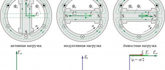
All these parameters can be recalculated through the phase angle that occurs between the voltage vector and current (f):
P = S * cos(f);
Q = S * sin(f);
S2 = P2 + Q2.
Household devices in which the total power can significantly exceed the active power include refrigerators, washing machines, fluorescent and some energy-saving lamps, as well as power electronics units.
On motors, active power and coefficient are usually indicated. In this case, the total power is calculated as follows: S = P / cos(f) = 750 / 0.78 = 962 W
There is also such a thing as peak or starting power. The fact is that accelerating engines requires much more effort than maintaining their rotation. Therefore, when you turn on appliances such as a refrigerator or washing machine, a short-term load surge occurs on a section of the circuit.
Starting currents can be several times higher than operating currents. When calculating the required cable cross-section and selecting the rating of the machine, this should be taken into account.
To do this, you need to determine the device with the greatest difference in starting and operating power and add it to the total value. The starting currents of other devices can be ignored, since the probability of simultaneous activation of motors for different consumers is practically zero.
Power current voltage, calculations for a single-phase network 220 V
Current strength I (in amperes, A) is calculated using the formula:
P – electrical full load (must be indicated in the technical data sheet of the device), W (watt)
U – voltage of the electrical network, V (volts)
The table below shows the load values of typical household electrical appliances and the current they consume (for a voltage of 220 V).
| electrical appliance | Power consumption, W | Current strength, A |
| Washing machine | 2000 – 2500 | 9,0 – 11,4 |
| Jacuzzi | 2000 – 2500 | 9,0 – 11,4 |
| Electric floor heating | 800 – 1400 | 3,6 – 6,4 |
| Stationary electric stove | 4500 – 8500 | 20,5 – 38,6 |
| microwave | 900 – 1300 | 4,1 – 5,9 |
| Dishwasher | 2000 — 2500 | 9,0 – 11,4 |
| Freezers, refrigerators | 140 — 300 | 0,6 – 1,4 |
| Electric meat grinder | 1100 — 1200 | 5,0 — 5,5 |
| Electric kettle | 1850 – 2000 | 8,4 – 9,0 |
| Electric coffee maker | 6з0 — 1200 | 3,0 – 5,5 |
| Juicer | 240 — 360 | 1,1 – 1,6 |
| Toaster | 640 — 1100 | 2,9 — 5,0 |
| Mixer | 250 — 400 | 1,1 – 1,8 |
| Hairdryer | 400 — 1600 | 1,8 – 7,3 |
| Iron | 900 — 1700 | 4,1 – 7,7 |
| Vacuum cleaner | 680 — 1400 | 3,1 – 6,4 |
| Fan | 250 — 400 | 1,0 – 1,8 |
| TV | 125 — 180 | 0,6 – 0,8 |
| Radio equipment | 70 — 100 | 0,3 – 0,5 |
| Lighting devices | 20 — 100 | 0,1 – 0,4 |
Various electricity consumers are connected through appropriate machines to the electric meter and then to a general machine, which must be designed for the load of the devices with which the apartment will be equipped. The wire that supplies power must also satisfy the load of energy consumers.
Linear and phase relationships
Nowadays, the practice of connecting household objects to three-phase electrical networks has become widespread.
This is justified for the following reasons:
- Significant energy consumption. In this case, connecting a high-power single-phase network will be very irrational due to the large cross-section of the cable and the high material consumption of the transformer.
- Availability of devices operating on three phases. The implementation of a circuit for connecting such a device to a single-phase circuit is not very simple and is fraught with interference that occurs, for example, when starting an asynchronous motor.
There are two ways to connect three-phase devices - “star” and “triangle”.
Schematic diagrams of power transmission in three phases. They received the name “star” and “triangle” due to their geometric similarity with these objects
In star-type circuits, the linear and phase currents are identical, and the linear voltage is 1.73 times greater than the phase voltage:
Il = If;
Ul = 1.73 * Uph.
This formula explains the known voltage ratio for household and low-voltage industrial networks with a frequency of 50 Hz: 220 / 380 V (according to the new GOST: 230 / 400 V).
With a triangle connection, on the contrary, the voltage is the same, and the linear currents are greater than the phase currents:
Il = 1.73 * Iph;
Ul = Uph.
These formulas can only be used with symmetrical phase loads. If the current consumption across the cables is different (unbalanced receiver), then calculations are carried out using the rules of vector algebra, and the resulting equalizing current is compensated by the neutral wire. However, for networks with connected household appliances, such cases are rare.
Collection of loads.
When the design scheme has been determined, when the decision has been made as to what will work in our design and what will “sit on our neck,” we should understand as thoroughly as possible what affects our design. And here we first encounter the concept of “load”. Load is any external influence that affects our structure. The list of loads is not that long:
- Load from its own weight (yes, even under its own weight an incorrectly calculated structure can break) and from the weight of other elements and materials.
- The load from the weight of people, furniture, equipment - in general, everything that may or may not exist, but it is important to take this into account and not miscalculate.
- Snow load.
- Wind load.
- Load from temperature influences (under the influence of temperatures, materials expand to the point of destruction; this phenomenon can also be expressed in the form of load).
- Seismic load.
As you can see, all this (well, with the exception of its own weight) comes from the outside, but has a significant impact on any design. Moreover, each load can be located in space in an arbitrary manner in relation to the calculation object - perpendicular, and at an angle, and along the axis. Loads can be combined with each other or exclude each other. In general, there are a lot of options, but we need to combine all this into a single system, find the worst option and design a structure that can bear this worst option on its own shoulders. What method is used in calculations to convert loads into a digestible format? After all, there can be a lot of loads, but looking at them, it is not immediately possible to understand whether they have a bad or good effect on the structure. It is to clarify the picture with loads that the calculation algorithm contains the next, very important step.
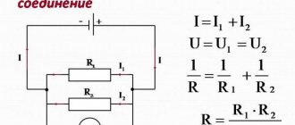
Relationship between basic quantities
The most common task faced by ordinary consumers is calculating the actual current strength. So how to correctly calculate amperage based on known voltage and power values? It is necessary to solve it by justifying the cross-sectional values of the cores and the rating of the machine, having technical information about the devices that will be powered into this circuit.
After calculating the current, cables with the smallest permissible cross-section are often selected. However, this is not always correct, since such a solution leads to significant restrictions when it is necessary to add new electrical appliances to the network.
Sometimes it is necessary to carry out reverse calculations and determine what total power can be connected to devices at a known voltage and maximum permissible current, which is limited by existing wiring.
You can solve these two problems for a single-phase circuit using a simple formula:
I = S/U;
S = U * I,
where S is the total total power of all electrical consumers.
A pie chart reflecting Ohm's law and expressing the dependence of power, current, voltage and resistance is suitable for calculating the parameters of a single-phase circuit
To solve the problem of calculating current using known or calculated values of power and voltage in a three-phase circuit, you need to know the total load imposed on each phase.
Both the required cross-section of the cable cores and the minimum permissible rating of the machine are selected according to the busiest line, considering that:
S = 3 * max{S1, S2, S3}.
I = S / (U * 1.73).
The permissible power for each phase can be calculated using the following formula:
S1,2,3 < S / 3 = I * U / 1.73,
where I is the maximum permissible current for existing wiring.
Video about the laws of electrical engineering
From the following video you can learn what electricity is and the power of electric current. Examples of practical application of the laws of electrical engineering are given.
Electricity has long been used by humans to satisfy their needs, but it is invisible, not perceived by the senses, and therefore difficult to understand. Power, current, voltage, all these characteristics of electricity were studied by famous scientists who gave them definitions and described the mutual connections between them using mathematical methods.
Power current voltage resistance
It should also be remembered that the value of electrical resistance is influenced by several factors:
- the structure of a substance that determines the presence of free electrons in a conductor and affects the resistivity
- cross-sectional area and length of the current conductor
- temperature
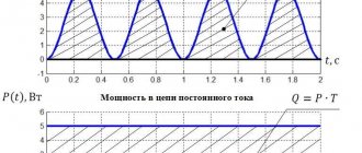
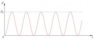
The table below shows general relationships for DC and AC circuits that can be used to analyze the operation of power supply circuits.
Perform a calculation to determine the forces.
Efforts are precisely the data that helps the engineer understand how the structure feels under the influence of the entire set of loads. If loads (external forces) are what influence the circuit from the outside, then forces are what each element of the design circuit feels directly in its own skin. A person stands on your leg - this is a load applied to your leg as a structure; you felt the pressure of this person’s weight, it causes certain tensions, deformations in you - this is a force in your leg.
One very experienced designer told me that when he checks the solutions of other engineers, he imagines himself in the place of the design. And sometimes he discovers that someone has attached a significant load not to the torso, arms or legs (in general, not to the hardy elements), but has hung it from the ear or nose, or even tried to catch it on the hair. These are jokes, but very deep ones. If you learn to imagine the work of a structure: to imagine in the form of images the forces arising in it from all loads, to imagine its deformations from these efforts, you can significantly make your life easier, and the life of the structure too.
There are not so many types of efforts; they are all collected in two concepts - forces and moments. Effort in the form of force is always direct, it either compresses, stretches, or tries to cut. The force in the form of a moment tries to bend or twist. If you take a rod (beam, column), its “well-being” is very easy to describe with several meanings:
- longitudinal force N, which either compresses or stretches along the axis;
- transverse force Q, which tries to cut the rod across the section (like we cut a carrot with a knife) or at least help it lose stability;
- bending moment M, which tends to bend the rod and bend it;
- torque T, which tries to twist the rod the same way we twist a wet towel.
All these are forces obtained as a result of structural calculations (taken from the typical Lyra example).
It turns out that loads are the initial data for the calculation, and efforts are the result. Why then does there arise confusion in concepts? I think because the efforts found are not the final result, but an intermediate one. Taking into account these efforts, the load-bearing capacity of the section is further checked, reinforcement is calculated and selected. And in this further calculation, efforts take the place of the initial data. And the next stage is emerging for us.