Exposed electrical wiring indoors
2.1.52.
Open laying of unprotected insulated wires directly on bases, on rollers, insulators, on cables and trays should be carried out: ¶ 1. At voltages above 42 V in rooms without increased danger and at voltages up to 42 V in any rooms - at a height of at least 2 m from the level of the floor or service area. 
2. For voltages above 42 V in high-risk and especially dangerous areas - at a height of at least 2.5 m from the floor or service area. 
These requirements do not apply to descents to switches, sockets, starting devices, panels, lamps installed on the wall. 
In industrial premises, descents of unprotected wires to switches, sockets, devices, panels, etc. must be protected from mechanical influences to a height of at least 1.5 m from the floor or service area. 
In domestic premises of industrial enterprises, in residential and public buildings, the specified slopes may not be protected from mechanical influences. 
In rooms accessible only to specially trained personnel, the height of openly laid unprotected insulated wires is not standardized. 
2.1.53. In crane spans, unprotected insulated wires should be laid at a height of at least 2.5 m from the level of the crane trolley platform (if the platform is located above the crane bridge deck) or from the crane bridge deck (if the deck is located above the trolley platform). If this is not possible, then protective devices must be installed to protect personnel on the trolley and crane bridge from accidentally touching the wires. A protective device must be installed along the entire length of the wires or on the crane bridge itself within the location of the wires. 
2.1.54. The height of open laying of protected insulated wires, cables, as well as wires and cables in pipes, boxes with a degree of protection not lower than IP20, in flexible metal hoses from the level of the floor or service area is not standardized. 
2.1.55. If unprotected insulated wires intersect with unprotected or protected insulated wires with a distance between the wires of less than 10 mm, then additional insulation must be applied to each unprotected wire at the intersection points. 
2.1.56. When crossing unprotected and protected wires and cables with pipelines, the clear distance between them must be at least 50 mm, and with pipelines containing flammable or flammable liquids and gases - at least 100 mm. When the distance from wires and cables to pipelines is less than 250 mm, wires and cables must be additionally protected from mechanical damage for a length of at least 250 mm in each direction from the pipeline. 
When crossing hot pipelines, wires and cables must be protected from high temperatures or must be designed accordingly. 
2.1.57. When laying parallel, the distance from wires and cables to pipelines must be at least 100 mm, and to pipelines with flammable or flammable liquids and gases - at least 400 mm. 
Wires and cables laid parallel to hot pipelines must be protected from high temperatures or must be designed accordingly. 
2.1.58. In places where wires and cables pass through walls, interfloor ceilings or where they exit outside, it is necessary to ensure the possibility of changing electrical wiring. To do this, the passage must be made in a pipe, duct, opening, etc. In order to prevent the penetration and accumulation of water and the spread of fire in places of passage through walls, ceilings or exits to the outside, the gaps between wires, cables and the pipe (duct, opening) should be sealed etc.), as well as backup pipes (ducts, openings, etc.) with an easily removable mass from non-combustible material. The seal must allow replacement, additional installation of new wires and cables and ensure the fire resistance limit of the opening is not less than the fire resistance limit of the wall (floor). 
2.1.59. When laying unprotected wires on insulating supports, the wires must be additionally insulated (for example, with an insulating pipe) in places where they pass through walls or ceilings. When these wires pass from one dry or wet room to another dry or wet room, all wires of one line can be laid in one insulating pipe. 
When passing wires from a dry or damp room to a damp one, from one damp room to another damp one, or when wires exit a room outside, each wire must be laid in a separate insulating pipe. When leaving a dry or damp room into a damp or outside building, wire connections must be made in a dry or damp room. 
2.1.60. On trays, supporting surfaces, cables, strings, strips and other supporting structures, it is allowed to lay wires and cables close to each other in bundles (groups) of various shapes (for example, round, rectangular in several layers). 
The wires and cables of each bundle must be fastened together. 
2.1.61. In boxes, wires and cables can be laid in multilayers with an ordered and random (scattered) mutual arrangement. The sum of the cross-sections of wires and cables, calculated by their outer diameters, including insulation and outer sheaths, should not exceed: for blind boxes, 35% of the clear cross-section of the box; for boxes with openable lids 40%. 
2.1.62. Permissible long-term currents on wires and cables laid in bundles (groups) or multilayered must be taken into account reducing factors that take into account the number and location of conductors (cores) in the bundle, the number and relative position of bundles (layers), as well as the presence of unloaded conductors. 
2.1.63. Pipes, ducts and flexible metal hoses of electrical wiring must be laid so that moisture cannot accumulate in them, including from condensation of vapors contained in the air. 
2.1.64. In dry, dust-free rooms, in which there are no vapors and gases that negatively affect the insulation and sheath of wires and cables, it is allowed to connect pipes, ducts and flexible metal hoses without sealing. 
The connection of pipes, ducts and flexible metal hoses to each other, as well as to ducts, electrical equipment housings, etc. must be done: 
2.1.65. The connection of steel pipes and boxes used as grounding or neutral protective conductors must comply with the requirements given in this chapter and Ch. 1.7. 
Source
Requirements for electrical wiring in residential buildings according to PUE 7
Requirements for electrical wiring of residential buildings are given in section 3 in chapter 3.1 of PUE 7 (Rules for electrical installations in the seventh edition).
Electrical wiring and cable lines
7.1.32. Internal wiring must be carried out taking into account the following:
- Electrical installations of different organizations, separate administratively and economically, located in the same building, can be connected by branches to a common supply line or fed by separate lines from the ASU or main switchboard.
- It is allowed to connect several risers to one line. On branches to each riser supplying apartments in residential buildings with more than 5 floors, a control device combined with a protection device should be installed.
- In residential buildings, lamps in staircases, lobbies, halls, floor corridors and other indoor premises outside apartments must be powered via independent lines from the ASU or separate group panels powered from the ASU. Connecting these lamps to floor and apartment panels is not allowed.
- For staircases and corridors with natural light, it is recommended to provide automatic control of electric lighting depending on the illumination created by natural light.
- It is recommended to supply electrical installations of non-residential buildings with separate lines.
7.1.33. Supply networks from substations to VU, ASU, main switchboard must be protected from short-circuit currents.
7.1.34. In buildings, cables and wires with copper conductors* should be used.
(* Until 2001, according to the existing construction backlog, the use of wires and cables with aluminum conductors is allowed)
Supply and distribution networks, as a rule, must be made of cables and wires with aluminum conductors if their design cross-section is 16 mm2 or more.
The power supply of individual electrical receivers related to the engineering equipment of buildings (pumps, fans, heaters, air conditioning units, etc.) can be provided by wires or cables with aluminum conductors with a cross-section of at least 2.5 mm2.
In museums, art galleries, and exhibition spaces, it is permitted to use lighting busbar trunking systems with a degree of protection IP20, in which the branch devices to the lamps have detachable contact connections located inside the busbar trunking box at the time of switching, and busbar trunking systems with a degree of protection IP44, in which the branching devices to the lamps are made with using plug connectors that ensure the branch circuit is broken until the plug is removed from the socket.
In these premises, lighting busbars must be powered from distribution points by independent lines.
In residential buildings, the cross-sections of copper conductors must correspond to the calculated values, but not be less than those indicated in Table 7.1.1.
7.1.35. In residential buildings, laying vertical sections of the distribution network inside apartments is not allowed.
It is prohibited to lay wires and cables from the floor panel in a common pipe, common box or channel that supply lines to different apartments.
Fire-retardant installation in a common pipe, common box or channel of building structures made of non-combustible materials, wires and cables of supply lines of apartments together with wires and cables of group lines of working lighting of staircases, floor corridors and other indoor premises is allowed.
Table 7.1.1. The smallest permissible cross-sections of cables and wires of electrical networks in residential buildings
| Line names | Smallest cross-section of cables and wires with copper conductors, mm2 |
| Group network lines | 1,5 |
| Lines from floor to apartment panels and to the settlement meter | 2,5 |
| Distribution network lines (risers) for supplying apartments | 4 |
7.1.36. In all buildings, group network lines laid from group, floor and apartment switchboards to general lighting fixtures, plug sockets and stationary electrical receivers must be three-wire (phase - L, neutral working - N and neutral protective - PE conductors).
Combining zero working and zero protective conductors of different group lines is not allowed.
The neutral working and neutral protective conductors are not allowed to be connected on panels under a common contact terminal.
Conductor cross-sections must meet the requirements of clause 7.1.45.
7.1.37. Electrical wiring in the premises should be replaced:
hidden - in the channels of building structures, embedded pipes;
open - in electrical skirting boards, boxes, etc.
In technical floors, undergrounds, unheated basements, attics, ventilation chambers, damp and especially damp rooms, it is recommended that electrical wiring be carried out openly.
In buildings with building structures made of non-combustible materials, permanent, monolithic installation of group networks is allowed in the grooves of walls, partitions, ceilings, under plaster, in the floor preparation layer or in the voids of building structures, carried out with cable or insulated wires in a protective sheath. The use of permanently embedded wiring in panels of walls, partitions and ceilings, made during their manufacture at construction industry factories or carried out in the mounting joints of panels during the installation of buildings, is not allowed.
7.1.38. Electrical networks laid behind non-passable suspended ceilings and in partitions are considered as hidden electrical wiring and should be carried out; behind ceilings and in the voids of partitions made of flammable materials in metal pipes with localization capabilities and in closed boxes; behind ceilings and in partitions made of non-combustible materials* - in pipes and ducts made of non-flammable materials, as well as flame retardant cables. In this case, it must be possible to replace wires and cables.
(* Suspended ceilings made of non-combustible materials mean those ceilings that are made of non-combustible materials, while other building structures located above suspended ceilings, including interfloor ceilings, are also made of non-combustible materials)
7.1.39. In rooms for cooking and eating, with the exception of apartment kitchens, open laying of cables is allowed. Open wiring of wires in these rooms is not allowed.
In apartment kitchens, the same types of electrical wiring can be used as in living rooms and corridors.
7.1.40. In saunas, bathrooms, toilets, showers, as a rule, hidden electrical wiring should be used. Open cable routing is allowed.
In saunas, bathrooms, toilets, showers, laying wires with metal sheaths, in metal pipes and metal sleeves is not allowed.
In saunas for zones 3 and 4 according to GOST R 50571.12-96 “Electrical installations of buildings. Part 7. Requirements for special electrical installations. Section 703: Premises Containing Sauna Heaters" electrical wiring with an insulation temperature rating of 170°C must be used.
(Note from the portal buildingclub.ru: more detailed information about electrical wiring in baths and saunas can be found on our portal: Electrical wiring in the bathroom, shower, sauna and bathhouse according to PUE 7
7.1.41. Electrical wiring in attics must be carried out in accordance with the requirements of Section. 2.
7.1.42. Through the basements and technical undergrounds of sections of the building, it is allowed to lay power cables with a voltage of up to 1 kV, supplying electrical receivers of other sections of the building. The specified cables are not considered as transit; laying transit cables through basements and technical undergrounds of buildings is prohibited.
7.1.43. Open laying of transit cables and wires through storerooms and warehouses is not permitted.
7.1.44. The lines supplying refrigeration units of trade and public catering enterprises must be laid from the ASU or main switchboard of these enterprises.
7.1.45. The selection of conductor cross-sections should be carried out in accordance with the requirements of the relevant chapters of the PUE.
(Note from the portal buildingclub.ru: you can find out more about the cross-section of conductors on our portal: requirements for cables according to PUE.
Single-phase two- and three-wire lines, as well as three-phase four- and five-wire lines when supplying single-phase loads, must have a cross-section of zero working (N) conductors equal to the cross-section of phase conductors.
Three-phase four- and five-wire lines when supplying three-phase symmetrical loads must have a cross-section of zero working (N) conductors equal to the cross-section of phase conductors, if the phase conductors have a cross-section of up to 16 mm2 for copper and 25 mm2 for aluminum, and for large cross-sections - at least 50 % cross-section of phase conductors.
The cross-section of PEN conductors must be at least the cross-section of N conductors and at least 10 mm2 for copper and 16 mm2 for aluminum, regardless of the cross-section of the phase conductors.
The cross-section of PE conductors must be equal to the cross-section of phase conductors with a cross-section of the latter up to 16 mm2, 16 mm2 with a cross-section of phase conductors from 16 to 35 mm2 and 50% of the cross-section of phase conductors with larger cross-sections.
The cross-section of PE conductors not included in the cable must be at least 2.5 mm2 - in the presence of mechanical protection and 4 mm2 - in its absence.
Grounding of electrical installations up to 1000V according to PUE 7
Color of conductors in the cable according to PUE 7, GOST R 50462 and GOST 31996
Color chart for cable cores according to GOST R 50462-2009
PUE point
I'm trying to find a section about cable inserts (Pipe in the wall), tell me where to read. (office type premises)
This is section 2 “Electricity sewerage.” In general, it would be good to clarify which cable is the input cable?
gesund wrote: I'm trying to find a section about cable inserts (Pipe in the wall), tell me where to read. (office type premises)
what did I find, thanks to Mikhail 53 for the tip where to look
PUE wrote: 2.1.58. In places where wires and cables pass through walls, interfloor ceilings or where they exit outside, it is necessary to ensure the possibility of changing electrical wiring. To do this, the passage must be made in a pipe, duct, opening, etc. In order to prevent the penetration and accumulation of water and the spread of fire in places of passage through walls, ceilings or exits to the outside, the gaps between wires, cables and the pipe (duct, opening) should be sealed etc.), as well as backup pipes (ducts, openings, etc.) with an easily removable mass from non-combustible material. The seal must allow replacement, additional installation of new wires and cables and ensure the fire resistance limit of the opening is not less than the fire resistance limit of the wall (floor).
Maybe I’ll ask around in this thread. Is it possible for Ng-Ls from the boiler room (introductory and Av. Osve) in transit through the battery in a metal hose (including through walls)?
gesund wrote: I'm trying to find a section about cable inserts (Pipe in the wall), tell me where to read. (office type premises)
AND? Wall penetrations, is a pipe needed? Wall material?
serks wrote: Ng-Ls from the boiler room (introductory and Av. Osve) in transit through the battery in a metal hose (including through the walls) is it possible?
Most likely no. And it's not about the metal sleeve. B-1A. Explosion hazard class of the premises. Study VSN 332-74.
PROPAB wrote: Most likely, no. And it's not about the metal sleeve. B-1A. Explosion hazard class of the premises. Study VSN 332-74.
3.16. The rules of this subsection apply to the installation of electrical wiring of power, lighting and secondary circuits with voltages up to 1000 V AC and DC, laid inside and outside buildings and structures using insulated installation wires of all sections and non-armored cables with rubber or plastic insulation with a cross-section of up to 16 mm2.
Openings in walls and ceilings must have a frame that prevents their destruction during operation. In places where wires and cables pass through walls, ceilings or where they exit outside, the gaps between the wires, cables and the pipe (duct, opening) should be sealed with an easily removable mass of non-combustible material.
The seal should be made on each side of the pipe (box, etc.).
When laying non-metallic pipes openly, sealing the places where they pass through fire barriers must be done with non-combustible materials immediately after laying cables or wires into the pipes.
Sealing the gaps between pipes (ducts, openings) and the building structure (see clause 2.25), as well as between wires and cables laid in pipes (ducts, openings), with an easily removable mass of fireproof material should provide fire resistance corresponding to the fire resistance of the building structure .
Source
Is it permissible to lay a cable along wooden walls in a country house and secure it with brackets? | Elcomelectro
About the company » Questions and answers » Is it permissible to lay a cable along wooden walls in a country house and secure it with brackets?
No, it is not permissible to lay and fasten the cable openly, on a combustible base, which includes wood.
Link to the regulatory framework:
PUE clause 2.1.32. When choosing the type of electrical wiring and the method of laying wires and cables, electrical safety and fire safety requirements must be taken into account. PUE clause 2.1.37. When laying open protected wires (cables) with shells made of combustible materials and unprotected wires, the clear distance from the wire (cable) to the surface of bases, structures, parts made of combustible materials must be at least 10 mm. If it is impossible to ensure the specified distance, the wire (cable) should be separated from the surface by a layer of fireproof material protruding from each side of the wire (cable) by at least 10 mm. PUE clause 2.1.38. When hidden laying of protected wires (cables) with shells made of combustible materials and unprotected wires in closed niches, in the voids of building structures (for example, between the wall and the cladding), in grooves, etc. With the presence of combustible structures, it is necessary to protect wires and cables with a continuous layer of fireproof material on all sides. PUE clause 2.1.39. When laying pipes and ducts made of non-combustible materials openly on non-combustible and non-combustible bases and structures, the clear distance from the pipe (duct) to the surface of structures and parts made of combustible materials must be at least 100 mm. If it is impossible to ensure the specified distance, the pipe (box) should be separated on all sides from these surfaces by a continuous layer of fireproof material (plaster, alabaster, cement mortar, concrete, etc.) with a thickness of at least 10 mm. PUE clause 2.1.40. When laying pipes and ducts made of non-combustible materials hidden in closed niches, in voids of building structures (for example, between a wall and cladding), in furrows, etc. pipes and ducts should be separated on all sides from the surfaces of structures and parts made of combustible materials by a continuous layer of non-combustible material with a thickness of at least 10 mm. PUE clause 2.1.41. When crossing short sections of electrical wiring with elements of building structures made of combustible materials, these sections must be made in compliance with the requirements of 2.1.36-2.1.40.
PUE clause 2.1.58. In places where wires and cables pass through walls, interfloor ceilings or where they exit outside, it is necessary to ensure the possibility of changing electrical wiring. To do this, the passage must be made in a pipe, box, opening, etc. In order to prevent the penetration and accumulation of water and the spread of fire in places of passage through walls, ceilings or exits to the outside, gaps between wires, cables and pipes (ducts, openings, etc.), as well as backup pipes (ducts, openings, etc.) should be sealed. .p.) easily removed mass from fireproof material. The seal must allow replacement, additional installation of new wires and cables and ensure the fire resistance limit of the opening is not less than the fire resistance limit of the wall (floor).
www.megaomm.ru
In what cases are sleeves used when cables pass through walls?
Hello, can you tell me in what cases are sleeves used when passing cables through walls?
In all cases, when cables are laid behind impenetrable suspended ceilings or pass through partitions with flammability group G2-G4, they must be laid in steel pipes or blind steel boxes with localization capability.
Can you tell me what standard technical documentation is written in it?
Do you need a sleeve when passing a metal grounding strip through a wall?
PUE, clause 2.1.58. In places where wires and cables pass through walls, interfloor ceilings or where they exit outside, it is necessary to ensure the possibility of changing electrical wiring. To do this, the passage must be made in a pipe, box, opening, etc. In order to prevent the penetration and accumulation of water and the spread of fire in places of passage through walls, ceilings or exits to the outside, gaps between wires, cables and pipes (ducts, openings, etc.), as well as backup pipes (ducts, openings, etc.) should be sealed. .p.) easily removed mass from fireproof material. The seal must allow replacement, additional installation of new wires and cables and ensure the fire resistance limit of the opening is not less than the fire resistance limit of the wall (floor).
clause 2.1.79. Entries into buildings are recommended to be made through walls in insulating pipes so that water cannot accumulate in the passage and penetrate into the building.
Source
How to route a cable through a wall according to the rules?
When installing electrical wiring and cable lines, you often have to solve the problem of how to route a wire or cable through the external walls of buildings and internal partitions. There are many requirements for the passage of electrical conductors through obstacles, and it is very important to comply with each of them, because this affects not only the ease of repair and replacement of wiring, but also the safety of its use. In this article we will tell you how to lay cables through a wall made of wood, brick and concrete in accordance with the requirements of regulatory documents.
Gasket requirements
The requirements for this type of work are regulated by two main regulatory documents. The first source is the PUE, which should always be consulted when it comes to installing electrical installations. The second document is SNiP 3.05.06-85, which describes the standards for the construction and installation of electrical devices. Information on this issue is also contained in Federal Law 123, which formulates fire safety requirements.
To carry out construction and installation work, it is necessary to have an appropriate project. If it is intended to lay a cable or wire through walls, the project must contain an architectural and construction part. The openings that a wall or partition must have through which wires and cables are supposed to be laid must be indicated on the project drawings.
Openings (openings) made in accordance with the design in walls, partitions, ceilings and foundations should not be framed by weakened areas that may collapse during operation. In general, installations through walls must meet the following requirements:
- the laying must provide the ability to replace wires and cables during operation.
- When installing wiring, it must be ensured that fire, smoke and moisture cannot spread through the installation openings from one room to another.
Compliance with these conditions is ensured by observing the following rules:
- Laying of cables and electrical wiring through fireproof walls and ceilings is carried out in pipes, ducts or directly in openings. At the same time, only protected (armored) cable can be laid in openings, without the use of additional protection. We talked about how to conduct electrical wiring in pipes in a separate article.
- If the wall, partition or ceiling is made of combustible material, conductor products are laid in steel pipes.
- The space between the wires and pipes or boxes, as well as all backup openings and boxes, are sealed. We also talked about how to seal a cable gland.
The material used to seal openings must be easily removable if necessary. The fire resistance of the sealant cannot be inferior to the fire resistance of the wall, partition and ceilings. Sealing using sealing material is carried out on both sides of pipes, ducts, and openings.
If the cable passes through the wall in a section of pipe, its bending radius, if any, should not exceed the permissible bending radius of the conductor grade used (this parameter is indicated in the technical specifications).
Installation technology
First, let's look at how to pass a power cable or wire through the wall of a wooden house or log building.
The first step is to determine the entry point where the wall is drilled. The diameter of the hole is determined based on the thickness of the steel pipe in which the conductor will be placed. Before stretching the cable, its edges should be carefully processed with a file to remove sharp burrs that could damage the insulation. For additional protection of the cable line, it is better to lay it in corrugation.
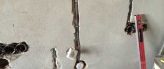
After installation, the pipe filling requirements must be met. In this case, you can use an asbestos cord, wrapping it around the cable and driving it tightly into the pipe on both sides. The photo shows a wooden wall and laying a power cable through it:
How to conduct electrical wiring through the wall and perform wiring is shown in the photo below:
Where:
- Steel pipe.
- Distribution box.
- Asbestos cement lining.
- Cable channel.
- Corrugation.
- Asbestos cement lining.
- Double socket.
For example, the options for how to route a cable through a brick wall are shown:
The sequence of work is as follows:
- An opening of the required size is made in the brick wall.
- A piece of corrugation (sleeve) is inserted into the prepared opening.
- A heat-shrinkable seal is installed on the pipe.
- The space between the sleeve and the opening is filled with mortar.
- A cable or wire, previously placed in a corrugated pipe, is passed through the sleeve.
- The space between the corrugation and the sleeve is sealed with one of the materials that meets the requirements of the rules.
- By thermal exposure (for example, using a hair dryer), the seal shrinks until the point of entry of the electrical conductor into the sleeve is completely sealed.
If the wall is made of concrete, the technology is the same as for a brick one. The photo below shows an example of laying a cable through a concrete wall:
For industrial use, inflatable cable seal technology is of interest. The seal is an inflatable chamber made of metalized laminate. The cable line is wrapped with a sealant on which a sealant is applied. The chamber is then inflated to fill the passage, after which the helium valve is securely locked. How the passage is filled is shown in the photo:
That's the whole technology of laying cable through a wall made of wood, concrete and brick. As you can see, laying a line through obstacles is not particularly difficult, the main thing is to be familiar with the requirements for electrical installation!
It will be useful to read:
Like(0)Dislike(0)
samelectrik.ru
Normative base
A few points from the regulatory documentation regarding cable passages:
this paragraph has a completely different content than the “similar” paragraph 3.18 of SNiP 3.05.06-85
6.3.1.13 The laying of cables and insulated wires in a protective sheath through building structures (walls, partitions, ceilings, etc.) must be carried out in textured holes (openings) using cable penetrations that comply with GOST R 53310.
The nodes where cables intersect enclosing building structures must have a fire resistance limit not lower than the required limits established for these structures.
6.4.1.25 Cable penetrations through walls, partitions and ceilings in production premises and cable structures must be made through sections of pipes, ducts, textured holes in reinforced concrete structures or open openings. Gaps in sections of pipes, ducts and openings after laying cables must be sealed with a special material that meets the requirements of GOST R 53310, SP 2.13130. The cable penetration must be made in such a way that its design allows adding new or changing previously laid cable lines during operation.
Mineral wool boards, fire-resistant sealants, thermally expanding materials or similar can be used as cable penetration material. Gaps in passages through walls may not be sealed if these walls or partitions are not standardized in the working documentation by the fire resistance limit.
We also have:
The following is the author's opinion, which may be somewhat inaccurate. I will be glad to receive critical comments and additions.
In my opinion, the PUE provides the most systematic approach; other documents somewhat complement and clarify it.
In clause 2.1.58 the following requirements can be highlighted:
How and with what can cable passages be sealed and why?
About the company » Questions and answers » How and with what can cable passages be sealed and why?
When constructing new buildings and structures, or when reconstructing old premises for various purposes, the projects must provide for the conditions and requirements for the placement of power supply communications in them. The main governing document is the PUE (electrical installation rules). The employees of our electrical laboratory are well aware of these requirements and have practically fulfilled them more than once. They constantly monitor changes in modern requirements, study additions, SNiPs, GOSTs and other regulations.
The documents detail the requirements, where and how, what cables and wires are laid. The requirements are described and take many factors into account:
- fire safety;
- operating conditions and location of buildings and structures;
- production sector in which electrical installations are involved;
- power and maximum current loads;
- types of wires and cables to be laid and many other details.
Basic requirements for cable passages through the wall
Paragraph 2.1.58 of the PUE states that in order to ensure the possibility of laying additional wiring or replacing the old one, cables and wires through the walls are laid in boxes or pipe cuttings. To prevent the penetration of fire or water, the gaps between the cable and the pipe are sealed with fire-resistant material, which can be easily removed if necessary. The fire resistance of the filler must be no lower than the fire resistance of the wall in which the cable passes.
Sections of SNiP 3.05.06-85 clarify many individual details and expand the capabilities of performers; the content names specific materials used to seal cable passages. In addition, it determines specific cases that through walls made of combustible material, pipes in passages must be metal or asbestos. Examples of the composition and proportion of the sealing mass for sealing cable passages are given:
- 1:10 cement and sand;
- 1:3 clay and sand;
- 1.5:11:1 clay-sand and cement;
- 2:1 gypsum and expanded perlite, other options;
- Red foam with fire safety certificate.
The gaps between the sleeves for cable passage and the wall are sealed with cement mortar or concrete. In cases where the walls are not a fire barrier, these gaps do not need to be sealed. When organizing cable passages through ceilings and walls, provision must be made for laying backup pipes, metal, asbestos or plastic, depending on the conditions. In addition to pipe cuttings, industrially manufactured sleeves are used for transitions of cables and wires of different diameters through walls. Nuclear power plants use special sealed devices. These structures contain plates with grooves for different cable diameters.
Employees of construction companies or managers of organizations that operate buildings cannot always correctly navigate the implementation of many requirements. It is especially important to fulfill the requirements efficiently and at minimal cost, to choose the best option and materials for sealing gaps in cable passages, taking into account the conditions at your facility.
Thanks to extensive practical experience and knowledge, and high-level technical support, the electrical laboratory can conduct high-quality tests. Our employees will tell you how, with what and why you need to seal the passages for cables, in each specific case, they will help you practically and draw up all the necessary documents for the work done.
www.megaomm.ru
Pass execution
You can see that various passage options are allowed: both in pieces of pipes and simply through the frame. The mandatory presence of sleeves is not required anywhere, and the term “sleeve” itself is not used. The main thing is not to damage the cable sheath when pulling and ensure the replacement of the wiring. The simplest solution is pipe sections, but you can also make a neat hole, plaster it and, if necessary, reinforce it. The use of corrugated pipes is possible only if they are not filled (to ensure replacement).
Filling the Passage
As you can see, regulatory documents operate in terms of “fire resistance limit of a structure” and this conceals a key nuance regarding the passage of cables.
If our wall does not have a standardized fire resistance limit, then PUE clause 2.1.58 and SP 76.13330.2016 clause 6.4.1.25 are slightly different in the interpretation of filling: PUE requires in any case to be sealed with fireproof material, but SP allows not to seal it. However, it “admits”: who needs extra holes - only mice and those who like to eavesdrop on what’s going on in the next office.
A small nuance: the PUE uses the term “fireproof”, which is absent in modern regulatory documentation, however, SNiP 2.01.02-85* (replaced by the muddy SP 112.13330.2011) has the definition “1.4. Building materials according to flammability (flammability) are divided into three groups: non-combustible (non-combustible), slow-burning (difficult to burn) and combustible (combustible).” Those. non-combustible materials are needed, and all installation “fireproof” and “fireproof” foams belong to group G1 - low-flammability.
Let's move on to structures that have a standardized fire resistance limit. If possible, this information should be obtained from the developer of fire protection systems or try to obtain from architects.
Usually in old administrative buildings it is impossible to obtain such documentation, for example, when work is only carried out on cosmetic repairs of existing premises of a couple of floors or the laying of communication networks.
The following is a simplified diagram that is not a “silver bullet”.
We determine structures with a standardized fire resistance limit:
If there are unfilled openings in the wall (for example, it is not brought to the ceiling above the level of the false ceiling or “stands” on the false floor), the thickness of the wall is one sheet of plywood - we do not have a wall in the fire protection sense and the fire resistance of such a structure is not standardized (I have seen server rooms with such walls).
Next, you need to determine the normalized fire resistance limit of such structures. With the help of the federal law “Technical Regulations on Fire Safety Requirements” dated July 22, 2008 N 123-FZ, we determine the functional hazard class of the building (type - FH.H). If our building contains several functional hazard classes, then we consider that there are fire barriers of type 1 between them. Then we find out what degree of fire resistance our building has and use tables 21 and 23 to determine the limits (this should be relatively easy for an engineer).
It is worth noting that all “dedicated” technical rooms must have a fire resistance of at least EI45/REI45; this can be achieved, for example, by using a half-brick brick wall (at least 65 mm thick) or a plasterboard partition of type C111, according to standard Knauf solutions ( in offices, partitions are usually made of type C112 with fire resistance EI60, but as the architects explained to me, this is to comply with noise standards).
If we cannot determine whether a wall has normalized fire resistance or not, we assume that it has normalized fire resistance.
GOST R 53310-2009 Cable penetrations, sealed entries and busbar penetrations. Fire safety requirements. Fire resistance test methods
3.1 cable penetration : A structural element, product or prefabricated structure intended for sealing the passage of cables through enclosing structures with rated fire resistance limits or fire barriers and preventing the spread of fire into adjacent rooms within a rated time. Cable penetration includes cables, embedded parts (ducts, trays, pipes, etc.), sealing materials and prefabricated or structural elements.
There is a small nuance for cable penetrations: they should not reduce the fire resistance limit of the structure, while filling door and window openings have weaker requirements.
The time has come to choose how and what to seal. There are many solutions on the market, but before using them, we be sure to check for a certificate in accordance with GOST R 53310-2009 (one-component “fire-fighting” foam usually has a certificate only in accordance with GOST 30247, which is not suitable for solving our problem).
The principle of operation for all penetrations is approximately the same - a fire-resistant material is used (burns slowly), which, when exposed to temperature, expands and closes all cavities.
When choosing a filling solution, it is important to pay attention to the thickness of the structure into which the cable penetration is installed.
Options for sealing fire penetrations
| Vulcan DP slabs from DKS | Fire-resistant panels Probably the cheapest method in terms of implementation: install mineral slabs in a textured hole, simultaneously treating everything with sealant. Can be used if you plan to rarely add or replace cables. |
| PYROBAG pillows from OBO BETTERMANN | Fire-resistant pillows The shell of the pillows is made of fiberglass, which is not affected by humidity. The installation is quite clean - you just need to “stuff” the pillows tightly. A good option for horizontal penetrations with frequent replacement or wiring of cables. Vertical penetrations require supporting structures to prevent the cushions from falling out under their own weight. There are also gaps between the pillows and, for example, DKS recommends sealing them with sealant to prevent smoke penetration. |
| CFS-BL blocks from Hilti | Foam blocks are actually an analogue of pillows, only they can be mounted without gaps. Cut with a stationery knife. Some manufacturers have round sections. |
| Foam from Hilti | Two-part foam and sealants/mastics Typically used to seal small penetrations or gaps in penetrations from larger “assemblies”. Sealants can be used in conjunction with mineral wool (see manufacturers' recommendations). |
| Penetration from Roxtec | Modular blocks of sealed penetrations When you have a lot of money, you need tightness and all that... This is really cool. There are “similar” solutions to Roxtec - CFS-T from Hilti and NTM from the Russian one. |
| Cuff "OGNEZA-PM-K" | Cuffs They are used mainly for pipes, but here the domestic one “distinguished itself”, which uses them as a cable penetration and even allows the cuffs to be recessed inside the passage hole (when installing a steel pipe), making them almost flush with the structure being protected. |
| EZ-Path from Cablofil | “Drawing boxes” Once upon a time, EZ-Path penetrations from Cablifil (part of the group) were unique on the market, but now similar penetrations “OGNEZA-PM-K” (modular) from “OGNEZA” have appeared, and also with a “killer” price CFS-SL GA from Hilti (round section). This option allows you to report and re-stretch cables quite often. |
| CFS-D from Hilti | Disc Amazing solution. I don’t know how Hilti received the necessary certificate, but at a price of 150 rubles. per disk - this is simply an excellent competitor to pena for single cables. |
| “Stop Fire” promotes the patented Stop Fire – it looks interesting and apparently inexpensive. I think it's worth paying attention. |
- Penetrations made of metal products with an area of up to 100 cm2 are not required to be grounded (PUE, clause 1.7.77, clause 6).
- When using pipes, the regulatory documentation does not stipulate anywhere how far the edges should protrude from the final coating.
- When using metal pipes, take into account “SP 76.13330.2016 Electrical devices. Updated version of SNiP 3.05.06-85” clause 6.3.6.2 Steel pipes used for electrical wiring should not have sharp cutting edges or jagged edges. They must have an internal surface that prevents damage to the wire insulation when they are pulled into the pipe and an anti-corrosion coating on the outer surface. For pipes embedded in building structures, external anti-corrosion coating is not required. Pipes laid in rooms with a chemically active environment, inside and outside, must have an anti-corrosion coating that is resistant to the conditions of this environment. Insulating sleeves should be installed where wires exit steel pipes.
- Typically, “black” electric-welded pipes are used, which have a seam along the pipe, since they are cheaper than water-gas pipes (VGP may be indicated in the description of the pipe).
- When running cables in external walls, it is necessary to slope towards the street to avoid moisture seepage. I didn’t find the slope value in the regulatory documentation; I usually indicate the range “5-15 degrees”.
- For cable penetrations in walls with normalized fire resistance, it is necessary to draw up inspection reports for hidden work (one report is allowed for several pieces - for example, for the floor of a building).
If you want to add something, please comment.