- home
- Measuring instruments
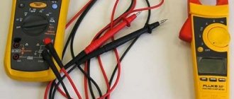
If, when measuring electric current, you use an ammeter with a limit of 1, 5 or even 10A, and the load will be greater than this limit value of the ammeter, then a measuring current transformer with the required coefficient can help you.
Let me remind you that the ammeter is connected in series to the electrical circuit. How will the ammeter be connected when using a current transformer?
In general, the TT will have two measuring leads for connecting an ammeter. The connection of the primary current to the CT occurs in series, but has features depending on the type of device, which we will discuss below.
Classification of electrical measuring instruments.
Electrical measuring instruments are classified according to the following criteria:
- 1) the type of quantity being measured (ammeters, voltmeters, ohmmeters, wattmeters, etc.);
- 2) principle of operation (magnetoelectric, electromagnetic, electrodynamic, thermal, electronic, etc.);
- 3) type of current (DC, AC, DC and AC devices);
- 4) degrees of accuracy (classes: 0,1; 0,2; 0,5; 1,0; 1,5; 2,5; 4,0).
The scale or the front panel of the device indicates the purpose, type of current, scale position (horizontal, vertical, at an angle), insulation breakdown voltage, accuracy class, operating conditions, year of manufacture, serial number.
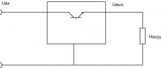
Connection circuits for an ammeter and a voltmeter.
Figures 4.3 and 4.4 show circuits for connecting a voltmeter and an ammeter through voltage (VT) and current (CT) measuring transformers, respectively.
Rice. 4.3. Voltage transformer.
Voltmeter connection diagram:
?/,, U2_
primary and secondary voltages of VT;
Wv W2
- primary and secondary windings of the voltage transformer;
V
- voltmeter
Rice.
4.4. Measuring current transformer.
Ammeter connection diagram: /p /2 - primary and secondary currents of the CT; Wv W2
— primary and secondary windings of the CT;
A
- ammeter
Ammeters, milliammeters and microammeters of various systems are used to measure current in electrical circuits. They are connected in series to the circuit, and all the current flowing in the circuit passes through them (Fig. 4.4). It is important that during various electrical measurements the ammeter influences the electrical mode of the circuit in which it is connected as little as possible. Therefore, the ammeter must have a low intrinsic resistance compared to the resistance of the circuit.
It is impossible to connect an ammeter to a current source (power supply) without a load, since in this case a large current will pass through its winding and it may burn out. For the same reason, the ammeter cannot be connected in parallel with the load.
Each ammeter is designed for a certain maximum current, above which the ammeter may burn out. If you need to use an ammeter to measure a current that exceeds the permissible current for a given ammeter, then a shunt is connected in parallel to the ammeter, i.e. expand the ammeter's measurement limits.
A shunt represents a relatively small but precisely known resistance. The circuit diagram for connecting an ammeter with a shunt is shown in Fig. 4.5, a.
The shunt must have four terminals to eliminate the influence of transient contact resistances on the shunt resistance. Shunts are made from manganin, an alloy whose temperature coefficient of resistance is practically zero.
Rice.
4.5. Ammeter connection diagram:
a -
with shunt;
6
- through a current transformer;
for circuit a: 1 -
shunt;
2
- load;
for scheme b: 1
— measuring current transformer;
2
- load
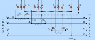
Rice. 4.6. Connection diagram of three ammeters through two current transformers:
L j and L2 - the beginning and end of the primary winding of the current transformer; And, and I2 - the beginning and end of the secondary winding of the current transformer; L
- ammeters;
iA, iB, ic -
currents in phases
Rice.
4.7. Voltmeter connection diagram:
R
- circuit resistance;
V—
voltmeter
Figure 4.6 shows a diagram of connecting three ammeters through two current transformers.
As can be seen from the diagram, a current iA passes through the first ammeter ,
through the second -
iB,
therefore, the current in the third ammeter, equal to the sum of two linear currents
iA
and
iB,
is equal to the third linear current:
ic = iA
+
iB.
Voltmeters are used to measure the voltage on a section of a circuit. The voltmeter is connected in parallel to those points of the circuit (M, N),
the voltage between which must be measured (Fig. 4.7).
The voltmeter should not change the voltage in the measured section of the circuit; for this reason, the current passing through the voltmeter must be much less than the current in the measured section.
In order for the voltmeter not to introduce noticeable distortions into the measured voltage, its resistance must be large compared to the resistance of the section of the circuit on which the voltage is measured. Any voltmeter is designed for a certain maximum voltage, but by connecting it in series with an additional resistance voltmeter /?ext you can measure higher voltages (Fig. 4.8, b).
Recommended Posts
The video also shows the range of adjustable voltage at the output of the set-top box. The fact is that during the operation of the variable resistor, sooner or later, its contact with the resistive shoe of the middle pin is broken and pin 4 Feed Back of the microcircuit ends up in the air, even if only for a millisecond. Article rating: 3 ratings, average: 5.00 out of 5 Loading If the connection is incorrect, the device display will show zero values.
Naturally, it heats up a lot. Most devices can be adjusted using built-in resistors.
This connection diagram does not provide for the use of a thin black contact. For example, I don’t worry about not very important designs and make shunts from a thick paper clip.
It is very difficult to accurately measure the tiny voltage drop across a low resistance shunt when the currents through it are small. Why simple?
It is more expensive than previous models, but also has a higher upper limit of measurements in V.
The display is two-color red and blue.
If necessary, then two or three in parallel. As you can see, the future conductors of the variable resistor R3 will be connected to the three points of the divider. dsn-vc288 calibration
Schemes for connecting ammeters through current transformers
In current measurement circuits, both when connecting devices directly and when connecting them through measuring current transformers, only ammeters are used.
Schemes for connecting ammeters through current transformers are shown in Fig. 1.
The current transformer provides a measurement error corresponding to its accuracy class only when measuring current in a certain range, and the load resistance in the secondary winding should not exceed a specified value. Thus, the accuracy class of current transformers of type TS-0.5 with a load resistance of 1.6 Ohms will be 1.0. When the load resistance increases to 3 ohms, the accuracy class decreases to 3.0, and when a load with a resistance of 5 ohms is connected to the secondary winding it becomes equal to 10.0.
Resistances when drawing up a real circuit can be estimated approximately as follows.
Resistance of connecting wires Rc = ρ l/S,
where ρ is the resistivity of the wire material (for copper wires ρ = 0.0175 μOhm x m, for aluminum wires ρ = 0.028 μOhm x m); l — length of connecting wires, m; S - cross-sectional area of wires, mm 2.
The total resistance of contact connections Rк can be taken equal to 0.05 - 0.1 Ohm.
The resistance of the device Z can be found in the reference book, indicated in the device passport or on its scale.
Rice. 1. Circuits for connecting ammeters through a current transformer: a - simple, b - with an intermediate transformer, c - for measuring currents exceeding the rated current of the transformer, d - with an intermediate transformer, with several ammeters, e - with an ammeter switch, c - c three-phase circuit with three ammeters, and the same with one ammeter with a switch.
The simplest and most common circuit for measuring current with a transformer in the circuit is shown in Fig. 1, a.
The current measured using this circuit is I = (I t n1 x I n x n)/(I t n 2 x N) = ktn x n x D p,
where I t n1 and I t n 2 are the rated primary and secondary currents of the current transformer; ktn = It1/It2 - transformation ratio; D p = Ip/N – device constant; D = Dp x k x t n - constant of the measuring circuit, n - instrument readings in scale divisions, N - number of divisions marked on the instrument scale, I p - full deflection current of the needle.
The accuracy class of the transformer is selected according to the accuracy class of the measuring device in accordance with table. 1.
Example. Let the ammeter RA have a scale with N = 150 divisions and a measurement limit of I p = 2.5A. In the measuring circuit in Fig. 1, and it is connected through a current transformer with rated primary and secondary currents I t n1 = 600 A and I t n 2 – 5 A, respectively. When measuring the current, the needle of the measuring device stopped against division n = 104.
Connecting an ammeter via a current transformer
Extending the measurement limits of the ammeter is possible if you use an additional device called a current transformer. It works on the principle of a conventional transformer, but the primary winding contains only a few turns. When the measured current passes through it, its value in the secondary winding will be several times less.
But such transformers have appropriate dimensions and are used only in industrial networks. In small-sized devices, their use is impractical.
Connecting an ammeter via a shunt
If the device is connected directly to the measuring circuit, without a current transformer, it is called a direct-connection ammeter.
Without a shunt, you can use devices designed for low current, on the order of milliamps. By shunting the measuring winding with a resistance greater than its own, we can change the measurement limit. The connection circuit is no different in complexity: the measured current passes through the shunt, and an ammeter is connected in parallel to it.
This is where Kirchhoff's first law comes into play. The measured current is divided into two: one flows through the frame, the second through the shunt.
They will relate to each other like this:
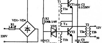
To power supply
Power supplies play an important role in leveling the network readings to the desired state. If not operated correctly, they can cause serious damage to expensive equipment by causing overheating. In order to avoid problems during their operation, and especially in cases where the power supply is made manually, it is advisable to use an inexpensive ammeter and voltmeter.
You can order a variety of models from China, but for standard devices operating from a home network, those that measure current from zero to 20 A and voltage up to 220 V are suitable. Almost all of them are small-sized and can be installed in small power supply cases.
Most devices can be adjusted using built-in resistors. In addition, they have high accuracy, almost 99%. The display displays six positions, three each for voltage and current. They can be powered either from a separate or built-in source.
To connect a voltmeter you need to understand the wires, there are five of them:
- Three thin ones. Black minus, red plus, yellow to measure the difference.
- Two fat ones. Red plus, black minus.
The first three cords are most often combined for convenience. The connection can be made through a special socket connector, or using soldering.
- It is necessary to decide from which power source the device will operate, separate or built-in.
- The black wires are connected and soldered to the minus of the power supply. Thus, a general minus is created.
- In the same way, you need to connect the thin red and yellow contacts. They are connected to the power contact.
- The remaining red pin will connect to the electrical load.
If the connection is incorrect, the device display will show zero values. In order for the measurements to be as close as possible to the actual ones, it is necessary to correctly observe the polarity of the supply contacts. Only connecting a thick red wire to the load will give an acceptable result.
Shunt resistance calculation
It follows that, knowing the total deflection current of the measuring system (Ipr) and the internal resistance of the frame (Rpr), it is possible to calculate the required shunt resistance (Rsh). And thereby change the measurement limit of the ammeter.
But, before converting a milliammeter into an ammeter, you need to solve two difficult problems: find out the total deflection current of the measuring system and its resistance. You can find this data if you know the type of milliammeter that is being converted. If this is not possible, a series of measurements will have to be taken. Resistance can be measured with a multimeter. But for the second parameter, you will need to supply current to the device from an external source, measuring its value using a digital ammeter.
But such a calculation of a shunt for an ammeter will not be accurate. It is impossible to ensure the required measurement accuracy using available means. A measurement system with a shunt has greater sensitivity to errors in determining the initial data. Therefore, in practice, precise adjustment of the shunt resistance and calibration of the ammeter are carried out.
Monitoring the car battery charge current
When using a charger, it is necessary to measure the current with an ammeter. This allows you to control the process of energy accumulation by the battery and avoid overcharging and undercharging. As a result, the battery life is significantly increased.
After turning on the circuit, the ammeter will show the charging current. The measurement accuracy and other characteristics of the ammeter are not so important for monitoring energy transfer. The measurement error is also not so important, since it is necessary to monitor the decrease in the readings of the ammeter needle. A device that shows the same value after several hours indicates that the battery is fully charged.
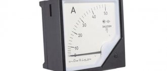
When operating a variety of equipment, it becomes necessary to control the current strength. Ammeter arrows or numbers on the screen of a discrete device show the user this physical quantity. The measurements taken are necessary both to maintain the operating condition and to signal the occurrence of an emergency.