15 259
Burykin Valery Ivanovich
Current generator
and
a voltage generator
. What is the difference? What is a Current Generator and what are its areas of application.
***
For work, it was necessary to find some clear description of what a current generator is (current stabilizer, current source)
, its areas of application and calculation examples. We couldn't find anything acceptable.
I had to start writing an article answering these questions myself.
And yet, we had to replace the generally accepted designations “delta” and “infinity” with words. Unfortunately, instead of them, when you try to read the text, question marks are displayed.
02/28/2012
***
The first thing we need to understand is what the differences are between a current generator and a voltage stabilizer.
Ideal voltage source
Ideal current and voltage sources are idealized energy sources. They have the ability to transfer energy to the parts of the electrical circuit connected to them; in other words, the energy they consume can be negative. Thus, ideal current and voltage sources refer to idealized active elements.
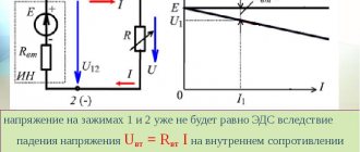
An ideal voltage source (voltage source, emf source) is an idealized active element, the voltage at the terminals of which does not depend on the current flowing through it. The voltage and at the terminals of the voltage source is equal to the electromotive force e (t) and can be an arbitrary function of time. In a particular case, e (t) = E_ may not depend on time. A source of this type is called a constant voltage source (constant emf source). The conventional graphic designation of the voltage source is shown in Fig. 1.12, a. The arrow inside the circle in the figure indicates the direction of e. d.s. For constant voltage sources, it is directed from the lower potential terminal to the higher potential terminal, while the voltage at the external terminals of the source is directed from the higher potential terminal to the lower potential terminal.
An external characteristic of any source of electrical energy is the dependence of the voltage at its terminals 01 of the source current. The external characteristic of a constant voltage source is a straight line parallel to the current axis (Fig. 1.12, b).
If you connect to the terminals of the source e. d.s. load resistance
As the load current decreases, the power released in it increases without limit. Because of this, the voltage source is sometimes called an infinite power source.
Components of electrical circuits
As is known, in order for an electric current to exist in conductors for a long time, it is necessary, firstly, the existence of a potential difference or voltage, and secondly, the replenishment of the required number of opposite charges for the occurrence of this potential difference. These conditions correspond to a certain set of elements called an electrical circuit.
Thus, an electrical circuit is a set of devices and objects that form a path for electric current and electromagnetic processes, which can be described using the concepts of emf, voltage and electric current. In addition, for electric current to flow, a closed electrical circuit is necessary. In general, an electrical circuit consists of a source of electrical energy, a receiver of electrical energy, connecting wires, as well as auxiliary elements that perform various functions.
A source of electrical energy is a device that converts non-electrical energy into electrical energy. For example, batteries convert the energy of chemical reactions into electrical energy, and generators convert mechanical energy. Thus, as is known from the previous article, energy sources are also called EMF sources.
A receiver of electrical energy, also called a load , is a device in which the opposite action of the energy source is performed, that is, electrical energy is converted into non-electrical energy. For example, in a light bulb, electrical energy is converted into light and thermal energy, and in an electric motor - into mechanical energy.
Auxiliary devices include various switching, distribution and measuring instruments and objects.
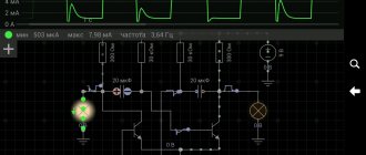
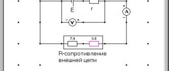
Electrical circuits are depicted in drawings in the form of electrical circuit diagrams , where each element of the electrical circuit has its own graphic element. Schematic diagrams show the purpose of each element of the circuit, as well as its interaction with other elements, but they are not very convenient for calculations. Therefore, when making calculations, they use so-called equivalent circuits , which, like circuit diagrams, are depicted using graphic elements, but the elements of equivalent circuits are selected so as to describe the operation of the electrical circuit with the necessary approximation. An example image of electrical circuit diagrams and equivalent circuits is shown below
Schematic diagram (left) and its equivalent circuit (right).
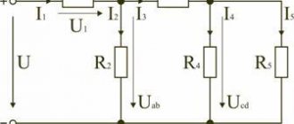
Equivalent circuits consist of the following elements: circuit, branch and node. A branch is one element or a sequential connection of several elements. A node is a junction of three or more branches. A contour is a closed path passing along branches so that not a single node or branch meets more than once.
Thus, knowing the parameters of all elements of the equivalent circuit, it is possible, using the laws of electrical engineering, to determine the electrical state of the entire electrical circuit, that is, to calculate its operating mode.
Ideal current source
An ideal current source (current source) is an idealized active element whose current does not depend on the voltage at its terminals. The source current i=j(t) can be an arbitrary function of time; in a particular case, it may not depend on time i(t) = J_ (direct current source). The external characteristics of the DC source are shown in Fig. 1.14, b.
The conventional graphic designation of the current source is shown in Fig. 1.14, a. The double arrow in the figure shows the direction of the current inside the source. For direct current sources, this direction coincides with the direction of movement of positive charges inside the source, i.e., with the direction from a terminal with a lower potential to a terminal with a higher potential.
The current of the current source and the voltage of the voltage source are parameters of idealized active elements, just as resistance, capacitance and inductance are parameters of the same idealized passive elements.
If you connect the load resistance to the external terminals of the current source (Fig. 1.15), then according to (1.9), (1.11) the voltage at the load resistance and the power released in the load will be equal, respectively:
As the voltage across the load increases and the power released in it increases indefinitely, therefore the current source, like the voltage source, is a source of infinite power).
The dependence of the current of the current source on the voltage has the same form as the dependence of the voltage of the voltage source on the current, therefore these sources are dual elements.
Measurement of phase-zero loop resistance
A “phase-zero” loop is an alternating current electrical circuit that can result from a short circuit between the wires: “phase” and “zero” or “phase” and “phase”. Destruction of insulation, mechanical damage or accidental connection of exposed cable sections to each other can cause this. In installations with a solidly grounded neutral, the neutral conductor is physically connected to the neutral of the transformer; it is connected to the ground loop. When there is a short circuit to the housing or the phases are connected to each other, a circuit (loop) is formed.
The main task of the measurements taken is to find out what the magnitude of the current through the loop will be during a short circuit. This is mandatory for the calculation and selection of protective equipment. A good result will be a low loop resistance, then the current Ik.c. will be the greatest. Its value determines how quickly the protective circuit breaker will operate.
The less time spent disconnecting a damaged or shorted circuit, the greater the chance of preventing a cable fire. If a person gets an electric shock due to touch or short circuit, automatic voltage relief will save his life.
Enterprises annually carry out a set of measurements of protective grounding and phase-zero loop resistance. If the results are unsatisfactory, a number of measures are taken:
- sections of the wire that do not meet the requirements for cross-sectional diameter are replaced;
- bolted connections are twisted with the obligatory installation of mortise washers;
- the protective grounding contours are opened and inspected for the integrity of welded joints and the condition of the grounding elements;
- if necessary, additional elements are added to the protective grounding loop;
- serial connection of device housings to a common ground bus is eliminated.
After completing a set of measures, measurements are repeated.
Checking the resistance of the phase-zero loop
Equivalent circuits for real sources
Idealized current and voltage sources can be considered as simplified models of real energy sources. Under certain conditions, in a fairly narrow range of currents and voltages, the external characteristics of a number of real energy sources can approach the characteristics of idealized active elements. Thus, the external characteristic of a galvanic element in the region of low currents has a form close to the external characteristic of the voltage source (see Fig. 1.12.6), and the external characteristic of the output stage on a transistor in a certain voltage range approaches the external characteristic of the current source (see Fig. 1.14.6).
At the same time, the properties of real energy sources differ significantly from the properties of idealized active elements. Real energy sources have finite power; their external characteristic, as a rule, is not parallel to the current axis or voltage axis, but intersects these axes at two characteristic points corresponding to the idle and short circuit modes (sometimes special types of protection are used in energy sources that exclude operation in extreme modes or in one of them).
With sufficient accuracy for practice, the external characteristics of most real energy sources can be approximately represented by a straight line intersecting the current and voltage axes at points 1 and 2 (Fig. 1.16, a):
corresponding to idle and source short circuit modes. Sources that have a linear external characteristic will be further called linearized energy sources (real).
Let us show that a linearized energy source can be represented by a modeling circuit consisting of an idealized voltage source E and internal resistance or an idealized current source J and internal conductivity. Indeed, the equation of a straight line passing through two points with coordinates has the form
Substituting (1.28), (1.29) into (1.30) and representing voltage u as a function of current i, we find an analytical expression for the external characteristic of the linearized source
In accordance with (1.31), the voltage of a linearized source consists of two components. The first one has the dimension of voltage and does not depend on the current flowing through the source. It can be interpreted as the voltage of some ideal voltage source with e. d.s. The second component of the source voltage is directly proportional to the current. It can be considered as a voltage drop across a certain resistance through which the source current i flows (this resistance will be called the internal resistance of the source in the future). So, equation (1.31) can be associated with the equivalent circuit of a linearized source, shown in Fig. 1.16, b. This replacement scheme is called
consistent. You can verify that the dependence of the voltage at the terminals of this circuit on the current is determined by the equation
equivalent to equation (1.31) and, therefore, the external characteristic of the circuit has the form shown in Fig. 1.16, a.
From the analysis of expression (1.32) it is clear that with a decrease in the internal resistance of the source, the external characteristic of a linearized source approaches the external characteristic of an ideal voltage source (Fig. 1.17, a). At = 0, a source with a linear external characteristic degenerates into an ideal voltage source. Thus, an ideal voltage source can be considered as an energy source whose internal resistance is zero.
Consider another linearized source equivalent circuit that contains an ideal current source. To do this, using (1.31), we express the current i as a function of the voltage at the source terminals:
As can be seen from expression (1.33), the current of the linearized source consists of two components. The first does not depend on the voltage at the source terminals. It can be considered as the current of some ideal current source. The second component of the current is directly proportional to the voltage at the terminals of the source, so it can be interpreted as the current flowing through some (internal) conductance to which a voltage u is applied. So, expression (1.33) can be associated with the equivalent circuit shown in Fig. 1.16, c. This equivalent circuit is called parallel.
The relationship between current and voltage at the terminals of the corresponding modeling circuit is determined by an equation equivalent to equation (1.33):
From equation (1.34) it is clear that with a decrease in the internal conductivity of the source, the external characteristic of the linearized source approaches the external characteristic of the ideal current source (Fig. 1.17, b). In the limit, at = 0, the linearized energy source degenerates into an ideal current source. Thus, an ideal current source can be considered as an energy source with infinitely small internal conductivity (infinitely large internal resistance).
Both considered linearized source equivalent circuits were obtained from the same equation (1.30), have the same external characteristic and, therefore, their behavior with respect to external terminals is exactly the same. The choice of one or another equivalent circuit can be made completely arbitrarily, however, in the process of studying the circuit, it may be necessary to switch from one circuit to another. Using expressions (1.31)—(1.34), you can find formulas for the transition from a series equivalent circuit to a parallel one
and from parallel circuit to serial
It is necessary to pay attention to the fact that the transition from one equivalent circuit to another is possible only for sources whose internal resistance has a finite value
Relations for mutual conversion of equivalent circuits of energy sources (1.35) and (1.36) are applicable for sources of direct current and voltage. Similar relationships can be obtained for sources in which the voltage u and current i are arbitrary functions of time.
Analyzing expressions (1 32), (1.34), it can be established that a circuit composed of a voltage source with a series-connected resistance and a circuit representing a parallel connection of a current source and conductivity are dual.
Source discharge capacity
The value depending on the strength of the discharge current is called the discharge capacity of the source. This is an electric charge that the source gives off during operation depending on the load current. This value can be considered constant conditionally. Thus, a starter battery with a discharge capacity C = 55 A*h will work for 10 hours at a discharge current of 5.5 A. When starting a cold or malfunctioning vehicle, the battery can be discharged in a few minutes.
In order to find the residual discharge capacity, charge-discharge cycles are performed. They are performed using load resistors. The discharge to the load resistance is carried out to the minimum permissible values of the electrolyte density. In this case, the operating time under load is measured. This is relevant during seasonal maintenance of batteries to identify self-discharge processes.
Car battery discharge capacity
The internal resistance of current sources is an important quantity. The methods used to reduce it are direct ways to increase the output power of the source, which means increasing the productivity of two-terminal networks. Correct measurement and calculation of the impedance of equivalent circuits allows us to bring the two-terminal network closer to the ideal source.