Problems on the topic “Lorentz force”
Even if you are not a beginner, before solving problems, read the general instructions and keep useful formulas on hand just in case.
Lorentz force problem No. 1
Condition
An electron with an energy of 300 eV moves perpendicular to the induction lines of a uniform magnetic field with a strength of 465 A/m. Determine the Lorentz force, speed and radius of the electron trajectory.
Solution
The electron speed can be found from the kinetic energy formula:
E k = m v 2 2 v = 2 E k m
The Lorentz force is a centripetal force, which means that according to Newton’s second law, we can write:
Magnetic induction is equal to the intensity multiplied by the magnetic constant. Substituting the previously found expression for speed into the formula for radius and Lorentz force, we write:
R = m 2 E kt q μ 0 H = 2 E kt q μ 0 HF l = q 2 E kt μ 0 H
Now all that remains is to substitute the values and calculate:
v = 2 4, 8 10 - 16 9, 1 10 - 31 = 3, 25 10 7 m s F l = 4 3, 14 10 - 7 465 1, 6 10 - 19 3, 25 10 7 = 3 10 - 15 N R = 2 4, 8 10 - 16 9, 1 10 - 31 4 3, 14 10 - 7 465 1, 6 10 - 19 = 0.32 m
Answer: v = 3.25 · 10 7 m s; F l = 3 10 - 15 N; R = 0.32 m .
Lorentz force problem No. 2
Condition
An alpha particle flies into a magnetic field with an induction of 1 Tesla perpendicular to the field lines. Find the angular momentum of the particle relative to the center of the circle along which it will move.
Solution
When a particle flies into the field perpendicular to the lines of force, the Lorentz force begins to act on it, which acts as a centripetal force. The radius of the circle along which the particle will move:
R = mv QB m = 6.65 10 - 27 kg - mass of alpha particles Q = 2 e = 3.2 10 - 19 K l - z a r i d a l f a c h a s t i c s
We find the angular momentum of the particle relative to the center of the circle using the formula:
L = mv R = m 2 v 2 QB = 6, 65 10 - 27 2 0, 35 10 7 2 3, 2 10 - 19 1 = 5, 42 10 - 21 kg m 2 s
Answer: 5, 42 10 - 21 k g m 2 s .
Lorentz force problem No. 3
Condition
In a uniform magnetic field with induction B = 0.5 T, a rod of length l = 20 cm rotates with a frequency n = 10 s-1. The axis of rotation is parallel to the induction lines and passes through one of the ends of the rod perpendicular to its axis. Determine the potential difference U at the ends of the rod.
Solution
Let us consider the physical essence of the processes taking place in the rod. When a rod moves in a magnetic field, an induced emf arises in it, which is caused by the action of the Lorentz force on the charges of the rod.
Under the influence of this force, a separation of charges occurs in the rod: free electrons move upward and a potential difference arises between the ends of the rod.
The charges at the ends of the rod create a field E, which prevents further separation of charges. At some point, the Lorentz force will be balanced with the force of the emerging field:
F l = e E E = F l e = ev B e = v B
The speed of the lower end of the rod, and therefore the speed of the electrons in it, can be found by knowing the rotation frequency and the length of the rod:
v = 2 π n l
Taking this into account, the expressions for the electric field strength will be rewritten:
E = 2 π nl B
The induced potential difference, by definition, is equal to:
U = E l U = 2 π nl 2 B = 2 3.14 10 - 1 0.2 2 0.5 = 1.3 V
Answer: 1.3 V.
Lorentz force problem No. 4
Condition
What force acts on a charge of 0.005 C moving in a magnetic field with an induction of 0.5 T at a speed of 150 m/s at an angle of 45 degrees to the magnetic induction vector?
Solution
This is the simplest problem to determine the Lorentz force. Let us recall the formula and write that the Lorentz force acts on the charge, equal to:
F = q v B sin α
Let's substitute the values and calculate:
F = 0.005 150 0.5 2 2 = 0.26 N
Answer: 0.26 N.
Lorentz force problem No. 5
Condition
A body with a charge of 0.8 mC moving in a magnetic field is acted upon by a force equal to 32 N. What is the speed of the body if the magnetic field vector is perpendicular to it?
Solution
This is a classic problem using the Lorentz force formula. Since the velocity and magnetic induction vectors are perpendicular, we can write:
F = qv B sin α = qv B v = F q B = 32 0, 8 10 - 3 2 = 20 10 3 m s
Answer: 20000 m/s.
Are you undergoing magnetostatics? You may also be interested in:
- Problems on the Biot-Savart-Laplace law.
- Problems on the magnetic field circulation theorem.
Definition and formula
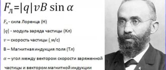
Hendrik Lorenz proved that electromagnetic induction interacts with charged particles. These interactions give rise to the Lorentz force. The force in question arises under the influence of magnetic induction. It is perpendicular to the velocity vector of the moving particle (see Fig. 1). A necessary condition for the occurrence of this force is the movement of an electric charge.
Rice. 1. Lorenz's conclusions
Pay attention to the location of the vectors (picture on the left, top). Vectors indicating the directions of velocity and Lorentz force lie in the same XOY plane, and they are located at an angle of 90º. The magnetic induction vector is oriented along the Z axis, perpendicular to the XOY plane, which means that in the selected coordinate system it is perpendicular to the force and velocity vectors.
According to Ampere's law:
Considering that
(here j is the current density, q is the unit charge, n is the number of charges per infinitesimal unit length of the conductor, S is the cross-section of the conductor, the symbol v denotes the modulus of the velocity of the moving particle), we write Ampere’s formula in the form:
Since nSdl is the total number of charges in the volume of the conductor, to find the force acting on a point charge, we divide the expression by the number of particles:
Modulus F is calculated by the formula:
From the formula it follows:
- The Lorentz force reaches its maximum value if the angle α is right.
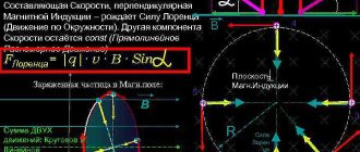
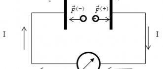
- If a point charge, for example, an electron, enters a medium of a uniform magnetic field, having a certain initial velocity perpendicular to the lines of electromagnetic induction, then the vector F will be perpendicular to the velocity vector. A point charge will be subject to centrifugal force, which will cause it to rotate in a circle. In this case, the work is equal to zero (see Fig. 2).
- If the angle between the induction vector and the particle speed is not 90º, then the charge will move in a spiral. The direction of rotation depends on the polarity of the charge (Fig. 3).
Rice. 2. Charged particle between the poles of magnets
Rice.
3. Orientation of the vector depending on the polarity of the charge From Figure 3 it can be seen that the vector F is directed in the opposite direction if the sign of the charge changes to the opposite (provided that the directions of the other vectors remain unchanged).
The trajectory of a particle is correctly called a helix. The radius of this helix (cyclotron radius) is determined by the compound initial velocity of the particle perpendicular to the field. The pitch of the helix along which the particle moves is determined by the composite initial velocity of the charge entering a uniform magnetic field. This component is directed parallel to the electromagnetic lines.
What is it measured in?
The dimension of the Lorentz force in the international SI system is newton (N). Of course, the modulus of the Lorentz force is such a tiny value compared to Newton that it is written in the form K×10-n N , where 0<K<1, and n is the order of the number 10.
When does it occur?
Magnetic fields do not react to a stationary electric charge, just as the Ampere force does not act on a de-energized conductor.
For the Lorentz force to arise, three conditions must be met:
- The particle must have a negative or positive charge.
- The charged particle must be in a magnetic field.
- The particle must be in motion, that is, the vector v ≠ 0.
If at least one of the conditions is not met, the Lorentz force does not arise.
Ampere power
If a metal conductor carrying current is placed in a magnetic field, then a force will act on this conductor from the side of the magnetic field, which is called the Ampere force
.
The origin of the Ampere force is easy to understand. After all, the current in a metal is the directional movement of electrons, and each electron is acted upon by the Lorentz force. All these Lorentz forces acting on free electrons have the same direction and the same magnitude; they add to each other and give the resulting Ampere force.
The direction of the Ampere force is determined by the same two rules formulated above.
Clockwise rule
.
Ampere's force is directed there, looking from where the shortest turn of the current to the field is visible counterclockwise
.
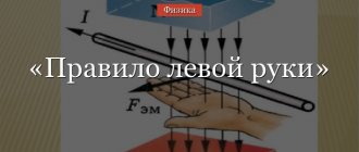
Left hand rule
.
We position the left hand so that the four fingers indicate the direction of the current, and the field lines enter the palm. Then the protruding thumb will indicate the direction of the Ampere force
.
The relative position of the current, field and Ampere force is shown in Fig. 2.
Rice. 2. Ampere power
In this figure, the conductor has a length of , and the angle between the directions of current and field is equal to . We will now derive an expression for the absolute value of the Ampere force.
Each free electron is acted upon by the Lorentz force:
where is the speed of directional movement of free electrons in the conductor.
Let be the number of free electrons in a given conductor, and let be their concentration (number per unit volume). Then:
where is the volume of the conductor and is its cross-sectional area. We get:
It is no coincidence that we have highlighted four factors in brackets. After all, this is nothing more than the strength of the current: (remember the expression of the strength of the current through the speed of the directional movement of free charges!). As a result, we arrive at the final formula for the Ampere force:
(2)
A good opportunity to practice finding the directions of the magnetic field and the Ampere force is provided by the interaction of parallel currents. It turns out that two parallel wires repel if the directions of the currents in them are opposite, and attract if the directions of the currents coincide (Fig. 3).
Rice. 3. Interaction of parallel currents
Be sure to check this out for yourself! Let's do this. First, we take an arbitrary point on the first wire and determine the direction of the magnetic field created at this point by the second wire (you know the rule - see the previous sheet>). Well, then we find the direction of the Ampere force acting on the first wire from the magnetic field of the second wire.
Lorentz force direction
We have already mentioned that the direction of the resulting Lorentz force, in addition to magnetic parameters, is determined (including) by the polarity of the charge. If we had the opportunity to observe a charged elementary particle located in a magnetic field, then from the vector of its movement we could determine the direction of the force vector F.
But in practice, it is very difficult to observe elementary charges due to their tiny sizes. Therefore, to determine this direction, a method is used, known as the left-hand rule (Fig. 4).
Rice. 4. Finding the Lorentz force vector
The palm must be turned so that the induction vector enters it. In the case of a positive charge, the extended fingers are positioned according to the movement of the particle. (for a negative charge, fingers point in the opposite direction). The thumb points at a right angle to the desired direction.
If the orientation of the particle velocity vector is known, then the directions of the remaining vectors can be determined by applying the right-hand rule, which is clear from Figure 5.
Rice. 5. Example of application of the right hand rule
Magnetism. Definitions, concepts and laws
A magnetic field. Magnetic field induction (magnetic induction)
The force field acting on moving electric charges, electric currents and magnetized bodies (magnets) is called a magnetic field. In turn, the magnetic field is created by moving charges, currents and magnets. The strength characteristic of a magnetic field is the magnetic induction vector. The concept of the magnetic induction vector is introduced on the basis of the following experimental facts: a) the orienting effect of a magnetic field on a closed flat circuit (frame) with current, b) the existence of a force acting on a conductor with current in a magnetic field, c) deflection of a beam of charged particles in a magnetic field field.
The effect of a magnetic field on a current-carrying frame
A flat frame with current, suspended on a thread in a uniform magnetic field, is subject to a moment of force that tends to rotate it in a certain way.
Rice. 3.3.1. Selecting the direction of the magnetic induction vector
The orienting effect of the field on the frame is used to select the direction of the magnetic induction vector. For this purpose, the concept of a positive normal to the frame is introduced, which is defined as a unit vector perpendicular to the plane of the frame and directed in the direction of movement of the gimlet (screw), if rotated in the direction of the current in the frame (Fig. 3.3.1). The direction of the magnetic induction vector at a given point in space is taken to be the direction of the positive normal to the frame, which is freely installed in a magnetic field in the vicinity of a given point. This direction coincides with the direction from the south pole to the north pole of a freely rotating magnetic needle.
A closed circuit with an area containing current creates a magnetic moment
(3.3.1)
The direction of the magnetic moment of the frame with current, freely established in a magnetic field, coincides with the direction of the magnetic induction vector.
Magnetic induction lines
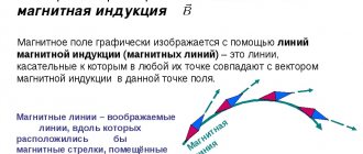
Graphically, the magnetic field is depicted using magnetic induction lines, which are lines whose tangents are directed in the same way as the vector at a given point, and whose density is proportional to the magnitude of the field at a given point. As an example in Fig. 3.3.2 shows the lines of magnetic induction created by a permanent magnet. Magnetic induction lines are always closed. Shown in Fig. 3.3.2 the lines are closed inside the magnet.
To calculate the magnetic field of an electric current, use the Biot-Savart-Laplace formula. According to this formula, magnetic
Rice. 3.3.2. Lines of magnetic induction created by a permanent magnet
the induction created by a piece of conductor of length , through which current flows, is equal to:
(3.3.2)
where is the radius vector drawn from the element to the observation point, is the angle between the vectors and is the magnetic permeability of the medium, and is the magnetic constant.
Pictures of magnetic field induction lines of direct current and solenoid
Formula (3.3.2) allows you to calculate the magnetic induction created by a conductor with a current of any shape. Thus, the magnitude of the magnetic induction of an infinitely long conductor with current at a distance from it is equal to
(3.3.3)
Magnetic induction lines are concentric circles in planes perpendicular to the conductor (Fig. 3.3.3). The direction of the magnetic induction of the current is determined by the gimlet rule: if the translational movement of the gimlet coincides with the direction of the current, then the rotation of the gimlet handle indicates the direction of the magnetic field.
The magnetic field inside a long solenoid (coil with current) far from its ends is uniform (Fig. 3.3.4). The magnetic induction inside the solenoid at points distant from its ends is equal to
(3.3.4)
where is the current flowing through the turns, is the number of turns, is the length of the solenoid. The magnetic field outside the solenoid is similar to the magnetic field of a permanent strip magnet (cf. Fig. 3.3.2). The end of the coil from which the induction lines emerge is analogous to the north pole of a magnet; the other end is similar to the south magnetic pole. The location of the coil poles and the direction of the magnetic field
Rice. 3.3.3. Magnetic induction lines of an infinitely long straight conductor carrying current Fig. 3.3.4. Solenoid magnetic induction lines
determined by the gimlet rule: if you rotate the handle of the gimlet along the current, then the movement of the gimlet will indicate the direction of the magnetic induction lines.
The concept of the Earth's magnetic field
The globe is a natural permanent magnet around which there is a magnetic field. The average value of magnetic induction near the earth's surface is .
Rice. 3.3.5. Geomagnetic field of the Earth
According to modern concepts, the main part of the Earth's magnetic field (geomagnetic field) is of intraterrestrial origin. This field is created by electric currents flowing in the liquid metal core of the planet. At distances not exceeding ( - radius of the Earth), the geomagnetic field has the structure shown in Fig. 3.3.5. It is close to the structure of the magnetic field of a magnetized ball (magnetic dipole). The radius of the dipole is about , its center is approximately 450 km away from the center of the Earth towards the Pacific Ocean, the axis of the dipole is inclined to the axis of rotation of the Earth at an angle of 11.5°. The Earth's magnetic poles are shifted relative to the geographic ones, and in the northern hemisphere there is a south magnetic pole with coordinates 75°53′ north latitude, 100°23′ west longitude, and in the southern hemisphere there is a north magnetic pole N with coordinates 66°06′ south latitude, 139 °36′E longitude. A small part (about 1%) of the magnetic field surrounding the Earth is created by electric currents flowing in the ionosphere - the ionized part of the Earth's upper atmosphere.
At distances exceeding , the structure of the Earth's magnetic field becomes more complex. Together with the solar wind (a flow of charged particles emitted by the Sun), the Earth's magnetic field forms the magnetosphere - a multiconnected system of electric and magnetic fields and flows of charged particles. The magnetosphere is asymmetrical relative to the day and night sides of the Earth. On the day side, the magnetosphere is compressed by the solar wind to a distance , on the night side it forms an elongated “tail” extending over many millions of kilometers.
Rice. 3.3.6. Movement of charged particles in the Earth's magnetic field
The Earth's magnetic field plays the role of a kind of “shield” that protects all living things from streams of charged cosmic particles (cosmic rays). At large distances from the Earth, the magnetic field is small, but covers vast areas of space. Acting on charged particles for a long time, it significantly changes their trajectories, deflecting particle flows from the Earth. At distances of approximately 500 to 60,000 km, charged particles move, winding along the induction line of the Earth's magnetic field (Fig. 3.3.6). They oscillate from one magnetic pole to another with a period of 0.1 to 1 s. This region of outer space is called the Earth's radiation belt. Only in the polar regions does a small portion of such particles invade the upper atmosphere from the Earth's radiation belt and cause auroras.
The force acting on a current-carrying conductor in a magnetic field. Ampere's law
A current-carrying conductor in a magnetic field is acted upon by the Ampere force:
(3.3.5) Fig. 3.3.7. Interaction of two parallel conductors with current
where is the length of the conductor segment with current, is the angle between the directions of the conductor segment and the magnetic induction vector, is the projection of the magnetic induction vector onto the normal to the conductor. The direction of the Ampere force is determined by the gimlet rule: the handle of the gimlet is rotated from vector to vector, then the direction of its translational movement determines the direction of the force, or by the left hand rule: if the left hand is positioned so that the component of the magnetic induction vector perpendicular to the conductor enters the palm, and the four outstretched fingers were directed along the current, then the thumb bent 90° will show the direction of the force acting on the conductor section.
Between two parallel infinitely long conductors through which direct currents flow (Fig. 3.3.7), an interaction force arises, the direction and magnitude of which can be found from Ampere’s law. Since the current-carrying conductor is in a field with induction created by the current-carrying conductor, the Ampere force is directed as shown in the figure. Conductors with identically directed currents attract, and conductors with oppositely directed currents repel. The modulus of the interaction force between sections of unit length of two infinite parallel conductors located at a distance from each other is equal to
(3.3.6)
The effect of a magnetic field on a moving charge. Lorentz force
A charge moving in a magnetic field with a speed is acted upon by the Lorentz force:
(3.3.7)
where is the projection of the magnetic induction vector onto the normal to the particle velocity. The direction of the Lorentz force is also determined by the left-hand rule or gimlet rule. In a uniform magnetic field, the induction vector of which is perpendicular to the speed of the charged particle, it moves in a circle of constant radius.
(3.3.8)
where is the mass of the particle, is the absolute value of its charge, is the speed of the particle, and is the magnetic field induction. The particle moves in a plane perpendicular to the vector. The Lorentz force in this case plays the role of a centripetal force. Its work is always zero, since the Lorentz force at each moment of time is perpendicular to the instantaneous velocity vector of the particle.
Magnetic properties of matter. Ampere's hypothesis
Magnetic interactions depend on the properties of the medium in which they occur. A physical quantity showing how many times the magnetic field induction in a homogeneous substance differs from the magnetic field induction in a vacuum is called the magnetic permeability of the substance:
(3.3.9)
According to Ampere's hypothesis, the magnetic properties of a substance are determined by closed electric currents inside it. In accordance with modern concepts, these currents are associated with the movement of electrons in the atoms of matter. Each electron moving in an atom around the nucleus in a closed orbit represents an elementary electron current, the magnetic moment of which, called the orbital magnetic moment, is perpendicular to the orbital plane.
The orbital magnetic moment of an atom is equal to the vector sum of the orbital magnetic moments of its electrons. If a substance consists of molecules, then the magnetic moment of the molecule is the vector sum of the orbital magnetic moments of its atoms. Thus, atoms and molecules generally have magnetic moments and can create a magnetic field.
Magnets are substances that can be magnetized in an external magnetic field, i.e. create its own (internal) magnetic field of the substance itself. Based on their properties, magnetic substances are divided into weakly magnetic and highly magnetic substances. Weakly magnetic substances include diamagnetic and paramagnetic materials. The main group of highly magnetic substances consists of ferromagnets.
Diamagnets are substances whose atoms or molecules do not have magnetic moments in the absence of an external magnetic field. Diamagnets are inert gases, a number of metals (gold, silver, mercury, zinc, copper), water, glass, and many organic compounds. When a diamagnetic substance is introduced into a magnetic field, an additional atomic (or molecular) current with a certain magnetic moment is induced in each of its atoms (or molecules). This current has such a direction that the magnetic field it creates is opposite to the external field. The magnetic induction vector of the internal field is directed against the external field and weakens it. This is the magnetization of diamagnetic materials, for which . Diamagnetism is a very weak effect. The magnetic permeability of even the strongest diamagnetic materials differs from unity by no more than ten thousandths.
Atoms (or molecules) that have a small magnetic moment in the absence of an external field are called paramagnetic, and the substances consisting of them are called paramagnetic. Paramagnetic materials include oxygen, nitrogen oxide, aluminum, platinum, alkali and alkaline earth metals, etc. In the absence of an external magnetic field, the thermal motion of paramagnetic atoms (molecules) prevents the occurrence of an ordered arrangement of magnetic moments of individual atoms (molecules), and the intrinsic magnetic field in the substance does not arises. When a paramagnetic substance is introduced into an external magnetic field, atomic (molecular) currents tend to arrange themselves so that their magnetic moments are parallel to the induction vector of the external field. The combined action of a magnetic field and thermal motion results in a predominant orientation of the magnetic moments of atoms (molecules) in the direction of the external field. A paramagnetic substance creates its own (internal) magnetic field, the induction vector of which is directed in the same direction as the induction vector of the external field. For paramagnets, but the effect of paramagnetism is very weak; magnetic permeability even for the strongest paramagnetic materials differs from unity by no more than thousandths.
Ferromagnets
Ferromagnets are a group of substances in a solid crystalline state that have magnetic properties due to the special interaction of atomic carriers of magnetism. Ferromagnetic materials include iron, nickel, cobalt, and a number of alloys. Ferromagnetism is explained by the quantum magnetic properties of electrons. The fact is that an electron, regardless of its presence in any system of particles (atom, molecule, crystal), has its own angular momentum (spin) and an associated intrinsic (spin) magnetic moment. An important feature of the electron spin is that in a magnetic field (both external and created by atomic and molecular currents) the spin can be oriented so that its projection onto the direction of the magnetic induction vector takes only two values, equal in magnitude and opposite in sign .
As a result of this, in some crystals, for example in iron crystals, conditions arise for the parallel orientation of the own magnetic moments of the electrons of a group of atoms.
Inside the ferromagnetic crystal, magnetized regions of the order of cm in size are formed, in which the electron spins are parallel. These spontaneously magnetized regions are called domains. In individual domains, magnetic fields have different directions and in a large crystal cancel each other out. When a ferromagnetic sample is introduced into an external magnetic field, partial ordering of the orientation of the magnetic moments of individual domains occurs and the resulting magnetic induction in the substance increases. With increasing magnetic induction of the external field, the degree of ordering of the domains increases. At a certain value of the external field induction, complete ordering of the orientation of the domains occurs and the increase in magnetic induction in the substance stops. This phenomenon is called magnetic saturation. In a state of saturation, the magnetic permeability of ferromagnets has very large values; for example, for iron, for permalloy (an alloy of nickel and iron).
When the external magnetic field is turned off, a significant portion of the domains in the ferromagnetic sample retain an ordered orientation—the sample becomes a permanent magnet. The orderly orientation of domains in a ferromagnet is disrupted by thermal vibrations of atoms in the crystal. The higher the temperature, the more intensely the order in the orientation of the domains is destroyed, as a result of which the sample becomes demagnetized. The temperature above which a substance loses its ferromagnetic properties is called the Curie temperature. The Curie temperature for iron is 770 °C, for nickel 356 °C, for cobalt 1130 °C.
Instructions for solving problems
Most of the problems in this section are related to either equilibrium or the motion of bodies under the influence of various forces, including the Ampere force and the Lorentz force. Therefore, along with the laws of magnetism and electromagnetic induction, it is necessary to use the laws of mechanics when solving problems.
Examples of problem solving
Task No. 3.3.1.
A particle of mass g, carrying a charge K, moves in a plane perpendicular to a uniform magnetic field with induction T. Find the period of revolution of the particle T. Ignore gravity.
Solution:
From the side of the magnetic field, the Lorentz force acts on the particle, perpendicular to the particle velocity and induction.
Under the influence of this force, the particle moves in a circle with radius , described by the equation where is the mass of the particle. Considering that the period of revolution of a particle is related to its speed and the radius of the circle by the relation, we obtain the answer :
Task No. 3.3.2.
A charged particle with a mass of kg flies at speed into a region with a constant and uniform magnetic field, the induction vector of which is perpendicular to . At what angle will the particle be deflected if the region occupied by the magnetic field in which the particle moves is limited by planes perpendicular to , the distance between which is ? Particle charge, magnetic field induction B = 0.01 Tesla. Ignore gravity.
Solution:
As soon as the particle is in the region occupied by the magnetic field, it will begin to be acted upon by the Lorentz force, directed perpendicular to the velocity of the particle. Under the influence of this force, the particle will move along a circular arc of radius R, which is easy to find from the equation of motion (see solution to problem 3.3.1): It can be seen from the figure that the angle a through which the particle will deviate is determined
the relationship between the radius of the arc R and the length L of the region occupied by the magnetic field. In particular, for R > L If , then the particle will describe a semicircle in the area occupied by the field, and . Thus, the answer to the problem can be formulated as follows: Given the numerical data from the problem conditions.
Task No. 3.3.3.
The square wire frame can rotate freely around a horizontal axis coinciding with one of its sides. The frame is placed in a uniform magnetic field with induction directed vertically. When current flows through the frame, it deviates from the vertical plane by an angle. Determine the magnetic field induction B if the cross-sectional area of the wire from which the frame is made is , and the density of the wire material is . Accept the free fall acceleration.
Solution:
The forces acting on individual segments of the frame from the magnetic field (Ampere forces) are shown in Figure a. It can be seen that the deviation of the frame from the vertical is caused by the force applied to the lower horizontal segment. The force is applied to the axis on which the frame rotates, and the forces act in the plane of the frame and can only cause its deformation. Thus, the frame is in equilibrium under the action of the forces shown in Figure b, where is the Ampere force, is the mass of the frame, is the length of one of its sides, and is the reaction force of the axis. The equation of moments relative to the axis of rotation of the frame has the form: Combining the written expressions, after simple transformations we obtain the answer :