The uninterrupted operation of the energy system is not always permanent. Natural or man-made external factors can make adjustments to its functionality. Taking this into account, pantographs (first and second reliability categories) are connected to more than two power sources. The load when switching to the main and backup power sources increases, therefore, for reliability, an ATS system (automatic transfer of reserve) is used.
- Simple circuits
Purpose and what is an AVR
The ATS system - an electrical switchboard input and switching switchgear - quickly switches the load to a backup source if problems arise with the energy plan on the main line. Before automatically switching to emergency operation, the system detects voltage problems in the input circuit and problems with the loads.
What is hidden under the abbreviation?
There are many ways to improve the operation of the energy supply system of buildings and residential buildings. Among them, AVR is of particular importance. The name ATS - automatic transfer of reserve - explains the purpose of the system. Sometimes “input” is replaced with “turn on,” which is not entirely correct. Turning on a reserve means starting a backup generator in certain cases.
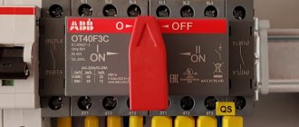
Typical AVR panel
AVR classification
The principle of classifying the operation of the working system allows us to identify the most complex sections of the voltage supply circuit. ATS blocks or cabinets are usually classified according to certain parameters:
- by the number of reserve sections (for example, ATS for two supplies to ensure greater reliability of power supply);
AVR cabinet for three inputs - by network type (usually single-phase ATS units are used, but there are devices for switching three-phase power that are used to start a generator);
Application of AVR in a private house
- by response time;
- by power of switched load;
- by voltage class (for example, in circuits for switching high-voltage lines).
The classification serves as a clear example of the operation of an energy supply system with control of switching from the primary source to the backup one. ATS speeds up and protects automatic switching.
What are the requirements for AVR?
To restore power supply in emergency situations, an ATS system that meets certain requirements is used.
- Ensuring uninterrupted power supply from the backup input in case of problems on the main line.
- The ability to restore the operation of the power supply system in the shortest possible time.
- One-time connection and disconnection of the load (for any reason).
- The process of transferring from the main power source to the backup unit is controlled by the ATS system before connecting to the reserve.
- The ATS system monitors the serviceability of the backup equipment control.
Purpose of AVR
The purpose of this system in electrical engineering is similar to the organization of uninterruptible power supply. The main task of automatically introducing backup power is to quickly restore power supply without human participation in this process. At large substations there are always two inputs into two sections of the switchgear, separated by a sectional switch, operating autonomously from each other. According to the PUE (electrical installation rules), automatic connection of backup power and supply to 2 inputs is a mandatory measure for providing electricity to consumers of the first category.
A simple example of the need for this system can be given regarding the lighting of some important protected area. That is, when the main input is turned off, the system itself will turn on the power from the backup source, while this important area will remain illuminated. The maximum that can occur is a short-term cessation of nutrition, which is even difficult to visually track. This depends on the speed of operation of the ATS; the time for switching on the reserve should be about 0.3–0.8 seconds.
How does the AVR work?
There are two types of system that differ in the type of input:
- Single-ended type ATS , where there is one working input, used until problems with the main line disappear. The system has a second - backup - input, which is connected in cases of emergency.
- A double-sided ATS does not have a separation based on operating and backup principles, since both inputs are a priority.
The first type is characterized by the presence of a function that makes it possible to switch to the operating mode as soon as the main mode is restored. The two-way type of ATS has its own advantages, so such a function is not provided there. And in the second case, there is no fundamental difference from which source the load comes.
You can see examples of both one-way and two-way operation of the ATS system.
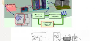
Principle of operation
To study working algorithms, you can use an example of an assembly based on a simple element base.
- Constant monitoring of the electrical parameters of the main line is provided by the contactor.
- Alternating current through the switch through a closed circuit enters the local network to consumers.
- If the voltage is lost, the induction coil will not be able to hold the rod.
- The spring will move the reserve input contact group through the actuator to close.
- At the same time, the main machine is turned off.
- When voltage appears in the operating line, the steps are performed in the reverse order.
Light bulbs in the corresponding circuits signal the start of certain modes.
On what basis does automatic reserve entry take place?
Regardless of the type of connection on a one-way or two-way basis, the system has a function for monitoring network parameters. For these purposes, a voltage control relay is used, as well as microprocessor control units, which does not affect the operation of the system as a whole. For example, you can consider the principle of operation of an ATS to ensure uninterrupted power supply for a single-phase consumer.
A simple circuit of a single-phase ATS
Designations:
- N – Zero.
- A – Working line.
- B – Backup power supply.
- L – Lamp acting as a voltage indicator.
- K1 – Relay coil.
- K1.1 – Contact group.
In normal mode, voltage is supplied to the indicator lamp with relay coil K1. Thus, the position of the normally closed (and normally open) contact changes. The load comes from the main source, line A. Voltage B disappears at input A, the lamp goes out, and the relay coil stops saturating, which, accordingly, leads to the contacts returning to their initial position. Thus, the load is switched on at input B.
When the voltage is restored at the main input, the relay is re-switched to source A, which corresponds to the principle of operation of a single-sided source.
This is a simplified diagram illustrating the processes occurring in the automatic transfer system, which is usually taken as an example for explanation.
Design and principle of operation
Regardless of the device for automatically switching on the reserve, its fundamental task is to monitor the parameters of the electrical network. For this purpose, voltage monitoring relays or units equipped with microprocessors can be used. There are two main types of device:
- One-way (OAVR) - one input works as the main one and is used until problems arise in the electrical main. The other acts as a backup and is switched on in emergency situations.
- Double-sided (DAVR) - both inputs perform the main work and are used as a reserve.
The design itself is a cabinet or ATS panel with contactors or automatic machines. Often in practice, designs with restoration are used, that is, as soon as the main network returns power, the backup power is turned off.
You may be interested in How to measure insulation resistance
In the event of a voltage drop in the controlled section of the circuit, the relay sends a signal to the ATS circuit. The absence of voltage in the network alone is not enough for the switching device to operate. For this, a number of other conditions must be present:
- There should be no short circuit in the area being tested, since turning on the backup power will be impossible and unacceptable.
- The input switch must be turned on so that in the absence of voltage the ATS does not accidentally start.
- The area from which the reserve will be powered must have voltage.
When all conditions are met, the transfer switch sends a signal to turn off the input switch of the de-energized network and turn on the ATS. The algorithm of actions occurs strictly in this order, that is, without disconnecting the input, the backup power will never turn on.
What schemes of operation of ATS exist?
Working examples show the success of using an autostart panel for uninterrupted power supply to a home.
Simple circuits
One of the variants of the ATS circuit shows the switching of electricity to the generator from the main line. The principle of short circuit protection is present here. This ATS is equipped with electrical and mechanical interlocking, which prevents two inputs from starting at the same time.
AVR diagram for home
Designations:
- AB1 and AB2 are two-pole circuit breakers on the main and backup inputs.
- K1 and K2 are contactor coils.
- K3 – contactor acting as a voltage relay.
- K1.1, K2.1 and K3.1 are normally closed contacts of the contactors.
- K1.2, K2.2, K3.2 and K2.3 are normally open contacts.
When automatically switching AB1 and AB2, the operation of the ATS system is as follows:
- Power supply from the main line is normal. When coil K3 is saturated, the voltage relay is triggered, which leads to the closure of K2.2 and K2.3 and the opening of K1.
- Power supply in emergency mode. If there are voltage problems on the main line, K3 is not saturated, the voltage drops below the permissible level, and the contacts return to their original position. Thus, voltage is supplied to coil K1, which causes the position of contacts K1.1 (the role of electrical protection) and K1.2 (which removes the blocking of power supply to the load) to change.
- Mechanical interlock triggered. In this case, a reversing starter is used (if there is one on the design of the electromechanical device).
An example of the operation of two simple automatic transfer switches for three-phase voltage, where, in one case, power supply is carried out according to a one-way scheme, and in the other - according to a two-way principle.
An example of one-way (B) and two-way (A) implementation of a simple three-phase ATS
Designations:
- AB1 and AB2 – three-pole circuit breakers;
- MP1 and MP2 – magnetic starters;
- RN – voltage relay;
- mp1.1 and mp2.1 – group normally open contacts;
- mp1.2 and mp2.2 – normally closed contacts;
- rn1 and rn2 – RN contacts.
Circuit A has two equal inputs to prevent simultaneous switching of lines. The principle of mutual interlocking is used here, as on contactors MP1 and MP2. Thanks to the sequence of automatic switching on AB1 and AB2, it will depend on which line the load will go. If AB1 is triggered first, then the MP1 starter is activated, and the MP1.2 contact is broken, which leads to the blocking of voltage to the MP2 coil. If source 1 is turned off, then the MP1 starter goes to its original position. And PM2 comes into action, which blocks the first starter and transfers the load supply from source 2. You can also switch sources manually using AB1 and AB2.
For the one-way principle of operation, circuit B is used. Its main difference is that a voltage relay (RN) is added to the connection circuit and when operation is restored, it returns the connection to source 1. But at the same time, RN2 opens, which turns off the starter MP2 and closes RN1, which allows you to connect MP1.
AVR
ATS (Automatic Transfer Switch) is a system for ensuring uninterrupted operation of energy consumers. In the event of a loss of the main power source, the ATS automatically starts the backup input.
According to the PUE, all consumers of electrical energy are divided into three categories:
- Category I - consumers in this group include those whose power supply disruption may result in danger to human life, significant material damage, a threat to state security, disruption of complex technological processes, etc.
All consumers belonging to this category must be powered from two independent power sources (this can be two transformer substations, or a transformer substations and a diesel generator). When one of the sources is turned off, the power supply should be interrupted only for the duration of automatic switching to the second input. It is obvious that in this case it is simply impossible to do without an automatic transfer system.
Also included in the first category is a special group of consumers who must function uninterruptedly in order to ensure an accident-free shutdown of production to prevent possible danger to human life, fires and explosions. For this group, three independent power sources are provided (two transformer substations and a diesel generator). For this group it is also necessary to use an ATS.
- Category II - this group includes electrical receivers whose power supply interruption can lead to massive under-supply of products, downtime of workers, machinery, and industrial vehicles
All objects falling into this category must also be powered from two independent power sources, but unlike the first category, some downtime is allowed until the power supply is restored. That is, in this case, automatic input systems can be used, but manual switching to the backup input is also allowed.
- Category III - all other electricity consumers.
And finally, the third category of energy consumers, for which electricity is supplied from a single power source. In this case, the interruption in power supply should not exceed one day. This category includes shops, office premises, private homes, etc. Although ATS systems do not seem to be provided for this category, you must agree that being without electricity for a day is not very comfortable, so whenever possible, ATSs are used here too.
As can be seen from all of the above, ATS devices are an integral part of uninterruptible power supply systems for electrical receivers.
According to the type of execution, the ATS is divided into
- Single-acting AVR
— in this design there are two inputs — the main one and the backup one. Both of them are connected to one section, to which the load is also connected. In normal mode, only the main input is in operation, and in the event of a malfunction, the ATS device turns off the main input and puts the reserve input into operation. As soon as voltage is restored at the main input, the system automatically switches to it. That is, the system has priority of the main input.
- AVR double-acting
— this circuit involves two inputs, each of which is connected to a separate section. The connection of two sections is made using a sectional switch. If one section loses power, it will automatically be connected to the working section. According to this scheme, both inputs are equal and do not have priority.
- Double-acting automatic transfer switch + input from diesel generator set.
In this case, everything works the same as in the previous scheme. The main difference is the presence of a third input from the diesel generator. The command to start the diesel generator set is given when the power is lost at both inputs.
Depending on the type of design, the ATS system can perform the functions of monitoring the state of circuit breakers at the input and output, protection against overvoltage, monitoring the phase sequence, selecting automatic or manual start, setting the time delay for turning on and off, indicating the network status, remote configuration and control, transmission of device status via SMS messages via GSM communication, etc. The functionality of the ATS can be very extensive; it all depends on the implemented scheme.
And there are many designs for ATS devices. Contactors, automatic switches or circuit breakers with motor drives are used as switching devices; phase control relays, programmable relays, and automatic switching control units are used as control and monitoring elements.
Despite this diversity, all ATS devices are based on the same operating logic - monitoring network parameters and automatically switching to the required input.
First, let's look at the simplest example using two circuit breakers and two contactors.
If there is voltage at the first input, power through the normally closed contact KM2.1 comes to the coil of the contactor KM1. The power contacts of KM1 are closed and the entire load will thus be connected to 1 input. If the power supply to input 1 disappears, contact KM1.1 will return to its original state, and voltage will be supplied to coil KM2.1. The power contacts of KM2.1 will close and the consumers will be powered from input 2. When power is restored to input 1, nothing will happen until power is lost from input 2. That is, the circuit does not have input priority and in order to switch to input 1 again, you will have to manually turn off the QF2 machine.
In fact, such a scheme can hardly be proposed for implementation, since it has a number of disadvantages. Firstly, the contactors do not have mechanical interlocking, there is no indication of the network status, there is no protection against over- or under-voltage; in the case of a three-phase version of this circuit, phase rotation control is required. So this is more of an example showing the general principle of operation of the ATS, rather than an actual working diagram.
But if you add a voltage relay to this circuit, it will take on a completely working form.
Firstly, the voltage relay provides protection against overvoltage and undervoltage, and secondly, it sets the priority of the main input. When power appears at input 1, the KSV relay contact will open the power supply circuit of the KM2 coil and automatic switching will occur from input 2 to main input 1.
Another example, this time of a three-phase ATS circuit.
Unlike the previous example, this diagram has a completely finished appearance. In addition to voltage control, there is also an indication of the input status, for which lamps HL1 and HL2 and mechanical blocking of the contactors (dashed line with a triangle) are responsible. In addition to the QF1 and QF2 circuit breakers, which protect power circuits, SF1, SF2 control circuit circuit breakers have been added.
In addition to relay logic, specialized backup power control units are often used in ATS devices for control and monitoring, such as BUAVR from NPP VEL, MAVR Meander, AVR-02G Euroavtomatika FiF, ATS022 ABB and others.
One of the most popular on the market is the BUAVR block.
BUAVR performs the functions of monitoring minimum and maximum voltage, monitoring phase rotation, phase asymmetry, breakage of one or more phases, controlling contactors or circuit breakers with motor drives, indicating the status of inputs and outputs.
Depending on the choice of mode, the BUAVR can operate:
- In automatic mode, with priority 1 input
- In automatic mode, with priority 2 inputs
- In automatic mode, without input priority
- With 1 input always on
- With input 2 always on
For different types of automatic transfer switches, BUAVR of various designs are produced - for example, one of the most popular models BUAVR1 is used in circuits for two inputs with one load, BUAVR.S - in circuits for two inputs, two loads with a sectional switch, BUAVR.2S - for two inputs, two loads with two sectional switches.
Below is a diagram of an ATS for two inputs with one load on contactors using the BUAVR1 block.
In the initial state, depending on the operating mode, which is set by the switch on the front panel, the BUAVR unit connects the load to one of the inputs. If during operation the voltage is outside the permissible values for a specified time (voltage settings and hold time are set using six switches Umin, t set off, Umax, t restore, t set on, U min2), the BUAVR turns off the load from this input and with a given time delay switches to the second input. The output relays of the BUAVR block K1 and K2 are used to turn on the contactors KM1 and KM2, respectively. On the front panel of the BUAVR there are LED indicators that indicate the presence, absence or unacceptable voltage values at inputs 1 and 2 (upper LEDs) and the status of the outputs (lower LEDs).
Also, recently, programmable relays have been widely used for various ATS circuits, for example Zelio Logic from Schneider Electric, Siemens Logo, Easy from Eaton.
They allow you to expand the functionality of standard ATS circuits, more flexibly customize the operating algorithm to suit your own needs, transmit information about the state of the device remotely, etc. Based on programmable relays, you can build various ATS circuits; Schneider Electric even published a brochure with typical circuits using Zelio Logic, but I will not dwell on them in detail, perhaps in the future I will write a separate article.
By the way, it should be noted that programmable relays do not have a voltage control function, so the use of a voltage relay or phase control is necessary.
In general, there are a lot of different ATS solutions and it will not be possible to talk about everything in one article, so in the future I plan to continue this topic.
Share on social media networks
Operating principle of industrial systems
The basic principles here remain unchanged. As an example, we can take an ATS circuit in the form of a standard cabinet. A relay is used here to monitor the state of each phase. If there are problems on one of them with voltage imbalance, you can always switch the load to the remaining line. This will restore the original power supply when problems with the main source disappear.
Diagram of a typical industrial AVR cabinet
Designations:
- AB1, AB2 – three-pole protection devices;
- S1, S2 – switches for manual mode;
- KM1, KM2 – contactors;
- RKF – phase control relay;
- L1, L2 – signal lamps to indicate the mode;
- km1.1, km2.1 km1.2, km2.2 and RKF1 are normally open contacts.
- km1.3, km2.3 and RKF2 are normally closed contacts.
Complete set of cabinet and panel
The configuration and operating rules of backup power input cabinets of types AVR-RN, AVRPA, AVRR are practically no different from each other. The device is a rectangular welded product with two doors.
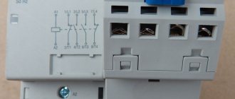
There are two panels mounted inside on which power and control devices are installed. When operating in networks with currents up to 100 A, cabinets made on the basis of PM 12 starters with silver contacts are used.
For currents above 100 A, vacuum contactors are installed. All connections of input and output circuits are made with a tool that ensures stable contact. Clamps designed for connecting stranded copper and armored wires with lugs are installed in the cabinet.
Installed starters must be designed for 300 thousand operations, and the shutdown time of the machines during a short circuit does not exceed 0.05 seconds. All devices must have appropriate symbols, and additionally, explanatory tags must be installed under them.
Cabinets usually have two cable entries: for the supply and backup wires, which are connected to pin blocks . The power part includes:
- power input block;
- output blocks connected to the corresponding machines;
- two input contactors;
- two voltage transformers.
You might be interested in AC Ammeter Device
The light indicators are powered by a voltage of 36 V. The installed AVR time relays provide the transformers with an uninterrupted supply of electricity. The equipment control system includes circuit breakers, warning lamps and phase control relays. The assembled cabinet can be used in conditions that exclude precipitation and at temperatures from - 45 °C to + 45 °C.
High-voltage circuits with ATS
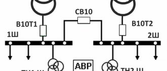
The operation of automatic transfer switches in high-voltage networks of the 1 kV class has a more complex scheme, although with a similar operating principle, as stated above. All triggering mechanisms do not change here. But in this scheme there are no backup transformers and each bus (Sh1 and Sh2) is connected to its main supply transformer (T1 and T2). The latter can, in certain circumstances, become backup sources with additional load. In normal mode, the CB10 switch is open and the ATS controls the TP via TN1 Ш and TN2 Ш.
When the power is blocked at Sh1, B10T1 is turned off and SV10 is turned on. Both sections or blocks start working from the same transformer. As soon as the source restores its operation, the ATS will reconnect the system to its original position.
Simplified diagram of 110/10 kV transformer substation
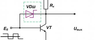
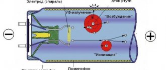
How microprocessor-based contactless systems work
ATS of this type have microprocessor control units. In operation of the device, the connection is made through semiconductor switches, which are more reliable.
Electronic unit AVR
Contactless automatic transfer switches have many advantages:
- There is no need for mechanical contact and there are no problems that can arise with it (burning or sticking, etc.).
- There is no need for mechanical locking.
- There is an extended range of control over all switching parameters.
The disadvantages include the difficulty of repairing an electronic type AVR. Implementing such a device scheme yourself will be problematic. You cannot do without special knowledge of electronics and programming knowledge.
With AVR water, the load on the operation of the entire system is significantly reduced, there will be fewer blockages, but it is easier to control the processes of switching electricity from the main source to the backup one and vice versa. Connection diagrams can always be found on the Internet or in the instructions.
System requirements
The functionality of the presented circuit is limited. If a fault in the main line is accompanied by a short circuit, restarting will damage the load. The reactive characteristics of electric motors have a certain influence. When connecting a machine or a powerful fan, a voltage drop can cause a false operation of the protection system.
Separately, you should consider the connection speed of the backup source. For significant time intervals, local protection circuits are triggered in some connected devices. Such situations are accompanied by malfunctions. They provoke breakdowns and accelerated wear of drives.
To eliminate the shortcomings, logical control circuits are used, created on the basis of electronic units with specialized software. Some components are equipped with mechanical locking units. Such elements remain operational even when the main and emergency power are completely disconnected.
Basic requirements for modern ATS:
- reliability of connecting a backup power source (PS) during peak loads and significant changes in network operating parameters;
- sufficient speed to prevent damage to electricity consumers;
- adjustable setting of threshold levels for turning on the protection system;
- blocking connection to a circuit with a short circuit and parallel connection of two inputs;
- single operation;
- automated check of the functional state of the backup IP.
Smooth switching is ensured by adding transformers to the circuit.