The development of an indoor electrical network can be planned both during its initial design and during the operation of ready-made wiring. In any case, you want to connect distribution boxes, mounted socket boxes, and switches with each other with minimal material costs. Disconnection of the power cable is not necessarily carried out exclusively in installation boxes, which are hub splitters. For example, there are many ways to connect a switch to an outlet, and vice versa. Some of the switching can be done in any box, the main thing is that there is no danger of shorting the contacts.
A typical example of combining a socket and a switch in one unit
Often in a corridor or hallway there is a need to combine a network connection point (socket) and a switch for several lighting groups. This method solves several problems:
- An extensive electrical outlet network in the corridor is usually not needed: there are no constantly used electrical appliances. However, there is a need to connect a vacuum cleaner or charger. In addition, a radiotelephone base unit can be installed in the hallway.
- There is little space on the walls in this room; there are wardrobes, a mirror, and a hanger. Part of the corridor is usually occupied by the input switchboard and metering device (meter). Therefore, compact placement of switching equipment is a key issue.
- By combining the socket and switch, wiring is saved and installation of an additional junction box is not required.
- If you additionally connect a second device: a switch to a socket, or vice versa, there is no need to damage the wall or organize a route for the power cable. The connection is made with minimal impact on the room.
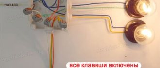
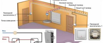
As can be seen in the illustration, to implement the entire circuit you will need one circuit breaker (in the panel it can be called “corridor: lighting, socket”), and one distribution box.
The zero bus N (blue color) passes through a kind of transit to the lighting groups and to the socket. The PE grounding is inserted into the socket body, and (if one of the lighting groups is in the bathroom) into the lamp body. The phase after the machine is connected to the socket through the distribution box. The disconnection occurs in the socket box. In this case, any terminal block is used: for example, WAGO.
A small section of wire connects the phase terminal in the socket and the input terminal of the two-key switch. Next, a phase is laid from the output terminals to each lighting group.
This scheme is usually used during design, since you still have to lay cables to different lighting groups. If such a solution is optional, you do not install additional boxes. The hole for the switch or socket box is made next to the already mounted device. All that remains is to install additional wiring.
If there is a need to connect the socket and lighting to different circuit breakers (for example, a power socket is used for a powerful electrical appliance), the phase is initiated along different power lines.
There is no need to use an additional distribution box; the phase wire passes through it in transit, without disconnection.
Tip: Leave a loop on each phase wire in the distribution box. With the future expansion of the network, you can cut the wiring and quickly organize the connection using the blocks.
In any case, this installation method saves both wiring and wall space. For example, let's look at the classic version of connecting a socket and switch to a distribution box.
Two cable routes were laid, the connection was in the junction box. Looking at the diagram, it becomes obvious that connecting the switch directly to the outlet is more efficient.
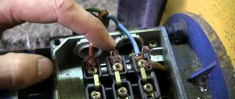
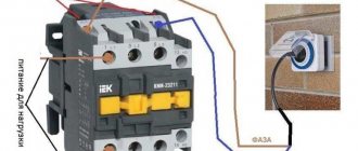
Installation of protective equipment
Next, you should take a closer look at the systems. In order for the power station to be fully functional, it is necessary to think about a device that protects against unexpected overloads, as well as short circuits.
Here you need a two-pole circuit breaker (you can replace it with an RCD or a circuit breaker with a voltage limiter).
The next step is to distribute the wires correctly. You should know that the blue wire goes to zero, the white wire goes to phase, and the yellow wire goes to ground.
- Using a sharp knife, carefully remove about one centimeter of insulation from each wire. Then the stripped tip is inserted into the contact terminal and secured with a screw. It's worth giving it a little tug to make sure it's securely in place.
- By analogy, the wire is connected to the distribution box. You should be careful and not confuse colors. Sometimes manufacturers change the shades of the phase and ground wires, but the neutral wire will always be blue. To avoid confusion in colors, you should always use wires from the same manufacturer.
- Next, the outer insulating layer is removed, the required piece of wire is measured, which will be needed to connect to the circuit breaker, stripped again and screwed on. The insulation is removed from the remaining wires, after which they are also connected to the machine.
A wire consisting of three cores is used in this case for a reason; the fact is that this is done for the future, i.e. Perhaps over time you will want to change the lampshade to a chandelier, this is where the third core will come in handy.
After all, it is much easier to perform another twist than to completely change the pattern. In addition, the third core can serve as grounding. This should be done if the lamp has a metal body or the room has high humidity.
A similar procedure is repeated on the outgoing piece of wire. That's all the machine is connected. Everything is located in the distribution box.
Step 3: Receptacle Location
Some lights have more than one switch. Some outlets have multiple slots. To be so small and in control, it can't offer all the possibilities.
Expert opinion
It-Technology, Electrical power and electronics specialist
Ask questions to the “Specialist for modernization of energy generation systems”
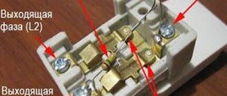
Effects Wrap the black wire around the copper screw on the right side of the socket and the white wire around the silver screw on the left side of the socket. Ask, I'm in touch!
How to connect a single-key switch from an outlet
The classic option: a common zero bus from the distribution box is connected to a light point.
Grounding goes through the same cable channel (if used). But the phase wire does not go directly to the lighting fixture. A single-key switch (located in the same housing as the socket) breaks the circuit between the phase contact in the socket box and the light source. Quite a common scheme. Such a block can often be found in lighting stores.
Another application for such a module is a switchable socket. Let's say you have an electrical appliance that should be turned off at night or when leaving the room. This could be a router that distributes Wi-Fi. The unit itself is located high, so it is not always possible to use the standard power button. By clicking the switch key, you will de-energize the equipment without touching the circuit breaker in the distribution panel. Or, on the contrary: the device must be powered under certain conditions. For example, power supply for an alarm system.
In this case, the phase wire inside the block is simply opened by a switch, and the power wiring is connected as to a regular socket.
Alexander Dyakov
- It is necessary to lay it from the distribution box to the socket box (and here and there it is worth leaving a small margin of about fifteen centimeters, which will be needed already at the connection stage).
- Another piece is laid, this time from the distribution box to the future lighting fixture.
- The wire is being laid from the machine to the distribution box to provide future power.
- A wire is laid from the meter showing the amount of electricity consumed or from the machine located at the entrance to the main machine, which goes to the main group.
If the switch is being added to an existing outlet
Minimizing the consequences - replacing the socket with a block. The procedure itself is simple; we drill a hole nearby for the box and carefully install the new module.
There is no need to install a power incoming cable; it is already in the socket. But the output wiring, to the lighting device, will have to be extended. This is an individual decision, there is no universal way. The connection diagram is very simple: both the neutral and phase wires are laid not from the box, but from the socket box.
Naturally, you will have to install contact blocks. Although many connect the output wire directly to the socket contacts: some models allow such a connection.
If there are several sockets in a group, you can replace any of them with a common block (socket - switch). You simply choose a convenient location (from which you can run the wire to the lamp) and connect the switch to the outlet.
If you need to organize an additional light point in the hallway, you can use wall sconces. They are placed in close proximity to the outlet-switch block, and you do not have to destroy a large piece of the wall for wiring.
General safety rules
Of course, before starting such work (especially on a completed power supply system), you should de-energize the line and check that there is no voltage. Selecting a power cable will not cause any difficulties: a cross-section of 1.5 mm² is sufficient for organizing lighting. Since we are connecting the switch to the socket, and not vice versa, the primary (socket) cable will be more powerful: 2.5 mm².
Rules for installing distribution boxes
First of all, let's look at the rules for installing junction boxes. After all, the reliability of your electrical network depends on this. Moreover, these rules are quite logical and do not require major investments.
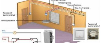
Location of distribution boxes in the apartment
So:
- First of all, remember that the junction box must be made of a material that matches the installation surface. So, on combustible surfaces, for example, wood, distribution boxes made of non-combustible materials should be installed. Usually it is metal.
- If the distribution box is mounted on a fireproof surface, for example, concrete, then boxes made of fire-resistant materials can be used. Usually, for these purposes, standard boxes made of special plastic are used, which are widely available in hardware stores.
- It is also worth remembering that, according to clause 2.1.22 of the Electrical Installation Code, a supply of wire must be provided at all branches and connections of conductors to ensure re-connection. The cost of following this rule will be mere pennies, but if it is necessary to reconnect, this reserve will become “golden”.
- It is also worth specifying the location of the distribution boxes. In general, it is not standardized, but they are usually located at the entrance to the room from the side of the door handle. The height of the distribution box is usually 10-20 cm from the ceiling. This allows you to protect it as much as possible from accidental touch and visually hide it.
Is it possible to connect an outlet to the switch?
Imagine the situation: you have renovated your premises, all the electrical wiring is walled up in the walls, and there are no backup boxes or socket boxes. An outlet needs to be installed in one of the rooms. Placing it next to the distribution box is irrational, the location is too high. But I don’t want to lay open wiring (especially, ditch the wall).
There is a switch in a convenient location that clearly has voltage. How to make a socket from a switch if it is possible to aesthetically place them next to each other?
To answer this question, let’s remember: what types of lighting schemes with switches are there?
Classic connection: tap from the distribution box.
The neutral conductor is inserted into the lamp from the box. In the box itself, a break in the phase cable is organized (it is opened using a switch), then the phase enters the lamp along the same path as the zero.
With this scheme, only the phase conductor is present in the body (installation box) of the switch. It will not be possible to organize a closed electrical circuit to connect an additional electrical appliance (via an outlet). You can use the phase from the switch, but you still have to lead the zero from the distribution box, which makes the idea pointless.
Conclusion: With this type of lighting arrangement, it is impossible to connect the socket to the switch.
The switch is located between the power source and the lighting fixture.
This scheme is less common, but in some rooms it is used. If at the design stage it was decided not to use distribution boxes in the lighting network, you are in luck. The switch wiring box contains both neutral and phase wires.
The sequence of work is as follows:
- We dismantle the existing switch without touching the installation box.
- We determine the routes for laying the input and output cables. If you have a diagram and plan for the electrical supply of the room, this is not difficult to do.
- Carefully drill a hole for the socket box.
- We install terminal blocks in the switch box and connect the socket according to the following diagram:
Safety regulations:
Since the current wiring is intended for lighting, most likely the cable cross-section is no more than 1.5 mm². The maximum possible load for such a cable (provided that it is copper): 3.3 kW. That is, not very powerful electrical appliances can be plugged into this outlet. The maximum is a vacuum cleaner. Well, phone chargers, a power supply for a router or an antenna amplifier - no problem.
Connecting spotlights
If it is necessary to use spotlights in an apartment, it is assumed that they can be supplied with either a standard mains voltage of 220 volts or reduced to a safe level of 12 volts.
The specific connection diagram for spotlights is selected taking into account the type of illuminators used, designed for the appropriate voltage.
Before connecting spotlights, you should pay attention to the fact that the order of their switching does not differ from the standard method.
Connection without power supply
Modern LED light bulbs are now produced at a voltage of 220 volts, since an electronic converter is installed inside the lamp, providing power to the LEDs at a reduced voltage. You can familiarize yourself with the design of an LED lamp in this article. The connection diagram for spotlights with 220-volt LED lamps is exactly the same as with conventional lamps.
Connection with power supply
When installing spotlights or LED strips, a transformer is additionally introduced into the circuit, reducing the voltage from 220 to 12 Volts. Now these devices are called power supplies , produced for various voltages and load power.
Please note: When connecting two or more points, the power supply is installed immediately after the switch (see diagram below).
Connection diagram for a group of spotlights with one step-down transformer:
Connection diagram for a group of spotlights with a transformer for each light:
Usually, to connect spotlights, an electronic converter (aka power supply) is selected, which compares favorably with other devices with the following advantages:
- Small size and light weight.
- Built-in short circuit protection.
- Smooth increase in voltage when turned on, extending the life of the bulbs.
- Ability to regulate and maintain stable power supply.
In addition, these devices are characterized by extremely low noise levels generated during operation of auxiliary equipment.
We invite you to watch a training video on the topic: “How to properly install spotlights.”
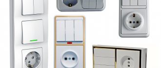
Technical features of devices
Before answering the question, it is advisable to describe the technical features of electrical appliances such as sockets and switches.
So, the function of an electrical outlet is to ensure the supply of electrical resources to connected consumers. Therefore, a prerequisite is the presence of two potentials at the terminals of this electrical appliance: phase (L) and zero (N). And in some cases (when connecting household appliances with a conductive housing) also protective grounding (PE).
If we talk about the light switch, then the task of this device is to close/open a ready-made circuit. In other words, the switch terminals are connected to an open circuit (usually a phase conductor is switched) and the terminals are connected to one potential: phase (L).
Based on the above, it becomes clear that it is not possible to connect a socket from the switch without changing the electrical installation, since for the full operation of any household appliance, two potentials are needed: phase (L) and zero (N), and a standard switch has only one of them.
If you connect a socket in parallel to the existing switch, then each time the consumer is connected to the network, the current will pass through the lamp (the lamp will glow). It is highly undesirable to use such a connection scheme due to its following limitations:
- Connecting high-power devices (more than 0.5 kW) to such an outlet will be accompanied by the passage of increased current through the filament, and the lamp will often fail;
- When connecting consumers, the supply voltage will drop (due to series-connected consumers) and some devices (for example, a refrigerator) will not be able to start at all;
- The simultaneous operation of two consumers can cause overheating of the conductors and cause emergency situations.
So how can you solve the problem?
Preparatory work
No matter how many keys your switch has (one, two or three), the preparatory work will be the same.
To begin with, you need to install a general distribution box and a mounting box for the switching device in the room; it is also called a socket box:
- If the walls in your room are made of PVC, plasterboard sheets, wood or MDF panels, install a special bit with serrated edges on a drill and make a hole. Insert the mounting box into it and fix it to the wall using self-tapping screws.
- For concrete or brick walls, make a hole using a hammer drill or drill with an attachment that works on concrete surfaces. But in this case, the mounting boxes must also be fixed using gypsum or alabaster mortar
As a rule, the installation of holes is carried out simultaneously with the laying of grooves. This is done purely for aesthetic reasons; there is a lot of dirt from such construction work, and it’s better to spray it once and clean it up. Grooves are grooves in the wall surface into which connecting wires will then be laid. They can be done using various tools:
- Hammer and chisel. This is an old ancestral method, its advantage is the complete absence of costs for purchasing tools (every man has a hammer and chisel). The disadvantage of this method of gating is that it takes a lot of time and effort.
- Bulgarian. This tool is often called the worst of the best. It’s convenient that grooves can be made quickly and without much effort. But it is from the grinder that there is a lot of noise and dust, and besides, it is not possible to make grooves of the same depth along the entire length, and it is almost impossible to work with the grinder in the corners of the room. So choose such a power tool as a last resort.
- Hammer. All you need is to purchase a special attachment for it - a strober or a spatula. In all other respects there are no shortcomings, it’s fast, convenient, the grooves are more or less even.
- Wall chaser. This is the ideal tool for this type of work. Works efficiently, safely and quickly. The grooves are smooth, there is no dust, since the wall chaser is connected to a construction vacuum cleaner. They are comfortable to work with and the tool does not make much noise. The only drawback is the high price. But there are services where you can rent a wall chaser.
Briefly about gating walls using the tools listed above is described in this video:
It is necessary to lay two-core wires into the grooves and fix them with cement or alabaster mortar.
So, the preparatory work is completed, the boxes are mounted, the wires are laid, and you can connect the light bulbs and switch.