Electrical wiring calculations are carried out at the design stage. First of all, the current strength in the circuits is calculated, based on this, automatic protective devices and the cross-section of wires and cables are selected. Of particular importance is the calculation of the machine according to the power of 380, which protects against overloads and short circuits. Too high a rating can lead to equipment failure, since the device will not have time to operate. The low rated current of the machine will cause the protection to operate even with minor overloads during peak hours.
How to calculate electric current power
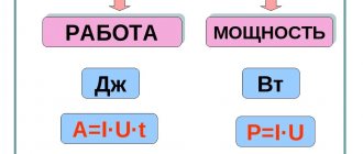
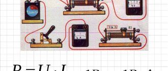
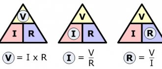
According to Ohm's law, current (I) is in direct proportion to voltage (U) and in inverse proportion to resistance (R). Power (P) is calculated by multiplying current by voltage. Thus, for a section of the circuit, the following formula is formed, by which the current is calculated: I = P/U.
Taking into account real conditions, one more component is added to this formula and when calculating a single-phase network, the following form is obtained: I = P/(U x cos φ).
A three-phase network is calculated a little differently. For this, the following formula is used: I = P/(1.73 x U x cos φ), in which the voltage U is conventionally 380 volts, cos φ is the power factor by which the active and reactive components of the load resistance are related to each other.
Modern power supplies have an insignificant reactive component, so the cos φ value is taken as 0.95. This does not apply to transformers and high-power electric motors with high inductive reactance. Calculation of networks where such devices can be connected is performed with a cos φ coefficient equivalent to 0.8. In other cases, the standard calculation method is used, followed by the application of a multiplying factor of 1.19, resulting from the ratio 0.95/0.8.
Three-phase or single-phase connection
Depending on what type of connection is used, the power consumption is determined differently.
In a single-phase network, the energy consumed is calculated using the simplest formula:
where cosϕ is the power factor characterizing the phase shift between current and voltage in a reactive load.
The power of a 3-phase network is the sum of consumption for each phase separately. The power formula for 3-phase current is as follows:
Ptotal=Uа∙Iа∙cosϕа+ Ub∙Ib∙cosϕb+ Uc∙Ic∙cosϕc,
where U, I, cosϕ are voltage, current and power factor in each phase, respectively.
For your information. It can be seen that in the general case, a three-phase connection requires a larger number of metering devices.
Sometimes you can calculate energy consumption using a simplified version. With symmetrical consumption, for example, when connecting an asynchronous motor, the consumption currents are the same, and the formula takes the following form:
Where:
- Uph, Iph – phase voltage and current;
- Ul, Il – linear voltage and current.
Selecting a machine by rated current
The considered formulas are widely used in calculations of the input circuit breaker. Using one of them - I = P/209 with a load P of 1 kW, the current strength for a single-phase network is 1000 W/209 = 4.78 A. The result can be rounded up to 5 A, since the actual voltage in the network is not always corresponds to 220 V.
Thus, the current strength was 5 A per 1 kW load. That is, a device with a power of more than 1 kW cannot be connected, for example, to an extension cord marked 5 A, since it is not designed for higher currents.
Circuit breakers have their own current rating. Based on this, it is easy to determine the load that they can withstand. There is a table to simplify the calculations. A machine rated 6 A corresponds to a power of 1.2 kW, 8 A – 1.6 kW, 10 A – 2 kW, 16 A – 3.2 kW, 20 A – 4 kW, 25 A – 5 kW, 32 A – 6, 4 kW, 40 A – 8 kW, 50 A – 10 kW, 63 A – 12.6 kW, 80 A – 16 kW, 100 A – 20 kW. Based on the same ratings, calculations are made for the machine's power at 380V.
How to find out your pattern
It’s easy to find out the number of phases in your house or apartment; to do this, you need to open the distribution panel and count the wires through which current enters the apartment.
With a single-phase network, the number of wires will be 2: phase, zero.
Sometimes there is a 3rd ground wire. In a three-phase wiring system there are 4: 3 phases, zero. A ground wire can also be added.
2 popular ways to connect a three-phase system:
- triangle;
- star.
Scheme “Triangle”
Each phase is connected to its neighbors. The current strength from the source is phase, between each other it is linear.
“Star” scheme
The phases are connected at one point. At this point, the total voltage will be 0. The current strength is only phase, and the voltage can vary from linear to phase. What does this give the user? Line voltage in the apartment is 380 V, and phase voltage is 220 V.
Most appliances operate at 220 V, but some appliances require more voltage: old electric stoves, powerful heaters and boilers, industrial power tools.
Thanks to this scheme, any device will work without problems.
Purpose and work
The first automatic device designed to protect an electrical circuit from overcurrents was invented by the American scientist studying electromagnetism, Charles Grafton Page in 1836. But only 40 years later a similar design was described by Edison . The modern type of protective devices was patented in 1924 by the Brown, Boveri & Cie corporation from Switzerland.
The innovation of the design is its reusability due to the ability to turn on the module when it is activated by pressing one button. The advantages over fuses were undeniable, and the accuracy of the machine was much better. When using the device in a network designed for 380 volts, all phases are switched off at once. This approach allows you to avoid skewed signal levels and the occurrence of overvoltages.
The direct purpose of a three-phase circuit breaker is to disconnect the line when a short circuit occurs in it or the power consumption of the devices is exceeded. Protection modules belong to the group of switching equipment and, due to their simple designs, ease of use and reliability, they are widely used in both domestic and industrial energy networks. Usually the device involves manual control , but some types are equipped with an electromagnetic or electric motor drive, which makes it possible to control them remotely.
Some users mistakenly assume that the machine protects the devices connected to it, but in fact this is not the case. It does not react in any way to the types and types of devices connected to it, and the only reason for its operation is overload and the appearance of overcurrent. At the same time, if the machine does not turn off the line, the electrical wiring will begin to heat up, which will lead to its damage or even fire.
The choice of an automatic protection module is related to the ability of the electrical line to withstand a current of a certain value, which is directly related to the cable material and its cross-section. In other words, when choosing a module, the main parameter is the power or maximum current that triggers the machine.
What are circuit breakers for and how do they work?
Modern AVs have two degrees of protection: thermal and electromagnetic. This allows you to protect the line from damage as a result of prolonged excess of the flowing current of the rated value, as well as a short circuit.
The main element of the thermal release is a plate made of two metals, which is called bimetallic. If it is exposed to a current of increased power for a sufficiently long time, it becomes flexible and, acting on the disconnecting element, causes the circuit breaker to operate.
The presence of an electromagnetic release determines the breaking capacity of the circuit breaker when the circuit is exposed to short-circuit overcurrents, which it cannot withstand.
An electromagnetic type release is a solenoid with a core, which, when a high power current passes through it, instantly moves towards the disconnecting element, turning off the protective device and de-energizing the network.
This makes it possible to protect the wire and devices from an electron flow, the value of which is much higher than that calculated for a cable of a particular cross-section.
What is important to know when connecting electrical appliances
So, having calculated the approximate rating of the required machine, you need to give an explanation regarding the power. Many people wonder whether it is possible to plug in very powerful electrical appliances into a regular outlet, such as an electric boiler, for example.
According to the rules of the PUE, connecting an electric boiler with a power of more than 3 kW to a regular outlet is unacceptable. And each outlet has its own specific characteristics. Most often, home sockets are rated at 16 amperes, and, therefore, electrical appliances with a power of no more than 3.5 kW can be connected to them.
Therefore, any more or less powerful electrical appliance must be connected only through a separate circuit breaker. Moreover, it is the phase wire that is supplied to the circuit breaker, and not the working zero. Thus, knowing the approximate power of the equipment, you can easily calculate the rating of the circuit breaker.
Calculator from Seasonic
Calculator from a well-known popular PSU manufacturer.
This calculator with a colorful interface differs from those considered in that as a result of calculations the user does not receive a power value. Since there are no power values, there is nothing to compare. But Seasonic is widely, and most importantly, positively known for its power supplies. The result of the calculations is an immediate offer of suitable power supplies from Seasonic.
Equipment for network short circuit protection
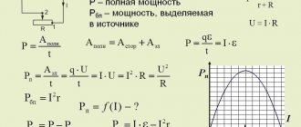
You already know how to calculate amps when you know the power and voltage, or calculate power when you know the current and voltage. But sometimes even accurate and correct calculations do not save you from a short circuit. An emergency can happen on a three-phase line for reasons beyond the control of the user: a foreign object hitting the wires, a break due to a falling tree. In this case, even if you have calculated the current strength as correctly as possible and your house has the most ideal wiring, a fire or failure of electrical appliances is possible. You can protect your network in the following ways:
- install a fuse. If the amperes in the electrical circuit exceed the permissible values, the fuse will melt and the circuit will be broken. The price of a fuse is 400-600 rubles. Choose a domestically produced product designed to work with our electrical networks;
- install a circuit breaker. This is modern equipment that reliably protects household appliances from premature failure due to problems with wires. Costs from 200 to 2 thousand rubles. It will blow in seconds, unlike a fuse, which will take about half a minute to open. When connecting, study detailed information about wire markings.
An automatic current switch will protect household appliances from damage due to a short circuit.
Modern electrical protection of engines
In the electrical equipment market, electric motor protection with the help of universal protective devices, the so-called automatic motors, which perform all the above protective functions, is gaining increasing popularity. These devices have a modular design and are mounted on a DIN rail and control the operation of power contactors. In addition to the above functions, some automatic motors allow you to precisely adjust various safety shutdown parameters.
Automatic motor with sensors - current coils
There are many varieties of modern automatic motors, which differ in switching power, set of functions, control method, connection diagram and appearance. To select the appropriate protective device for a particular motor, you need to know its rated and starting current parameters, and you also need to determine the required set of protective functions and options.
The cost of automatic motors is directly proportional to the power of the electric motor and functional protective capabilities. The world leaders in the production of motor protective circuit breakers are the following well-known brands: Schneider Electric, ABB, IEK, Novatek electro, and others.
Variety of motor protection devices available on the market
The motor protection circuit breaker (universal unit) shown in the figure below allows you to configure the rated and starting current of the electric motor, permissible voltage thresholds, and can monitor the mechanical load on the electric motor shaft. The quality of insulation of the electric motor windings is also monitored with the ability to set a ban on switching on.
Continuous monitoring of multiple operating parameters helps extend the life of the engine and driven equipment. A special additional information exchange unit allows you to connect the device to automatic control systems.
Universal protection block
Current cut-off (for AV with two-stage VTX)
The current cutoff of the switch is adjusted from the starting current of the electric motor, which consists of a periodic component, almost unchanged throughout the entire starting time, and an aperiodic component, attenuating over several periods. Failure to operate the cut-off when starting the engine is ensured by selecting the current cut-off according to the expression:
1.05 – coefficient taking into account that in normal mode it can be 5% higher than the rated voltage of the electric motor;
kз – safety factor;
ka – coefficient taking into account the presence of an aperiodic component in the starting current of the electric motor;
kр – coefficient that takes into account the possible spread of the cut-off current relative to the setting.
Instantaneous current cut-off (for AV with three-stage VTX)
For switches with a three-stage protective characteristic, the instantaneous cutoff of the switch is adjusted from the peak value of the starting current of the electric motor:
In addition, the current cut-off must reliably protect the electric motor from the minimum short-circuit current in case of damage at the end of the cable line: where (1)
k.RI – minimum single-phase short-circuit current at the end of the cable, calculated taking into account the current-limiting effect of the arc at the fault site.
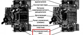
Operating principle
After connecting the power and load electrical lines to the three-phase circuit breaker, it is turned on by moving the lever to the upper position. As a result, the lever engages through the latch with the switching contact. The formed connection is ensured by the displacement of the movable contact group relative to their holder.
In a normal situation, current passes through the contact between the power and moving contacts. Then it goes to the bimetallic plate and the solenoid winding, and from it it goes to the terminal and the load connected to the machine.
If a current begins to flow through the switch with a value exceeding the permissible value, then the bimetallic plate begins to heat up. Due to the different thermal expansion of the metals, it bends, eventually breaking the contact. The current strength at which the connection breaks depends on the thickness of the plate. The thermomagnetic release is characterized by slow operation, although it can detect even small changes in the current value. Its setting is carried out at the factory by changing the distance between the plate and the moving contact. An adjusting screw is used for this.
But for a current that instantly increases its value, the reaction rate of the bimetallic plate will be extremely low, so a solenoid is used along with it. In the normal state, the core is pushed out by the spring and closes the contact of the machine. When the signal value is abnormal, the magnetic field rapidly increases in the coil turns, the flows of which draw the core inward, overcoming the action of the spring, and this leads to a break in the circuit.
The operation of the electromagnetic release occurs in a fraction of a second, while it does not respond to currents slightly exceeding the rated ones. Simultaneously with the disconnection of the entire three-phase line, the lever is also lowered, which will again need to be moved to the upper position to connect the load to the network.
Cable section selection calculator
The calculation is made based on data on power, current, cable length and temperature, conductor material and method of laying it.
The calculation results are applicable for determining the cross-section of the conductor when selecting cables and wires during the design of power supply and electrical installation work, as well as for calculating the expected voltage losses.
*The calculation values obtained are for reference only and are not recommended for use in the design of energy supply systems without professional expertise and verification of compliance with regulatory documents.
Calculation of cable cross-section by power and length
In order to choose the right cable, you first need to know its cross-section. Our online calculator for calculating cable cross-section by length and power will help you calculate the cable cross-section required for safe operation of electrical wiring. A cable with the correct cross-section will avoid overheating, short circuits and failure of electrical equipment.
How to calculate cable cross-section by power and length
To obtain data on the cross-section of the cable core, you need to enter the following parameters:
- Total load current in watts or amperes (total power of electrical appliances or current of consumers);
- Rated mains voltage;
- Cable purpose: for three-phase or single-phase electrical wiring;
- Cable length from source to load;
- Cable core material;
To correctly calculate the cross-section, be sure to indicate all initial values!
ALLOWS YOU TO CARRY OUT THE FOLLOWING CALCULATIONS
- Calculation of current/power cross-section . Calculation of cable cross-section based on load power or current, taking into account installation conditions, conductor material and voltage losses, as well as selection of cables and wires.
- Maximum current across the section . Determination of the maximum current and load on a known conductor.
- Selecting a protection device . Calculation of circuit breakers, RCDs and differential circuit breakers, as well as their selection.
- 1
- 2
- 3
- 4
- 5
- 6
- 7
- 8
- 1
- 2
- 3
- 4
- 5
- 6
- 7
- 8
- 0.5
- 0.75
- 1
- 1.5
- 2.5
- 4
- 6
- 10
- 16
- 25
- 35
- 50
- 70
- 95
- 120
- 150
- 185
- 240
- Motor 3x400V
- Motor 230V
- TEN lamp 3x400V
- TEN lamp 230V
- Air conditioner
- Washing machine
- Fridge
- Computer, TV
- Incandescent lamp
- Energy saving lamp
- LED lamp
Are there any requirements for additional cores?
| Yes, core "0" is required |
| Yes, a ground wire is required |
| At your cable/wire | veins |
The calculator allows you to calculate the cable cross-section by current or power, based on the parameters of the total load and incoming voltage. This takes into account the installation conditions, wire manufacturing materials, possible voltage losses and conductor selection criteria. The functionality of the section also allows you to calculate the maximum current and load on a conductor with specified parameters and select protection devices (circuit breakers, differential circuit breakers and RCDs).
How to calculate the cable cross-section:
- Indicate the source data (current or power), voltage, conductor material (copper or aluminum), type of wiring (open or closed in a pipe), number of wires (when laying communications in a pipe);
- Note additional conditions (wire length, permissible losses);
- Click on the “Calculate” button and save the resulting parameters;
- Click the “Select” button to select products in our Catalog based on the calculation results.
The cable cross-section calculator works online and offline. Please note: it is for guidance only and cannot guarantee 100% accuracy of the calculations. However, the more valid data you enter into the appropriate fields, the higher the match rate will be.
vote
Article rating
Characteristics of a three-phase system
A three-phase power supply system is characterized by several voltage and current values. It all depends on between which points of the circuit the measurements are made:
- between the phase wire and the neutral – phase voltage Uph;
- between individual phases – linear Ul.
The relationship between these parameters:
With symmetrical load distribution, the currents in all wires are equal. In a four-wire circuit (with a grounded zero), there is no current in the neutral conductor, so even if the zero is broken, the network continues to function normally.
In the case where the energy consumption differs between phases, some current flows in the neutral wire. A complete break in the neutral conductor causes a phase imbalance, so the voltage on the wires can change in the range from zero to linear.
The reactive nature of the load is taken into account by the power factor cosϕ. This value comes from the theory of complex numbers, which are used when it is necessary to calculate the parameters of alternating current circuits. In the case of an active load, cosϕ = 1, but the more reactive the consumers are, the more the coefficient decreases, showing how the real power decreases relative to the total.
Important! Therefore, to correctly calculate and reduce the load on generating equipment, power factor correctors are installed in reactive circuits. Circuits with a corrector bring the cosϕ coefficient closer to unity.