To understand what electricity losses are in electrical networks, you will need to understand the power supply system itself. It consists of a number of structural elements, each of which, under certain conditions, contributes to overhead costs. In addition, they may be associated with the need to meet their own needs for auxiliary equipment of substations. From this it follows that it is almost impossible to do without losses in electrical circuits.
Types and structure
Approximate structure of losses
Losses in electric networks from the point of view of energy saving are the difference between the volume of electricity supplied by the supplier and the energy that the consumer actually receives. In order to standardize and calculate their real value, the following classification was adopted:
- technological losses;
- operating (commercial) costs;
- actual non-productive expenses.
Technical losses are caused by the peculiarities of laying power supply lines, as well as energy dissipation at the contacts.
This also includes the selection of part of the supplied electrical energy for the needs of auxiliary equipment. The technological component includes costs in load circuits and the climate component. The second factor - commercial - is usually associated with such unavoidable reasons as the error of instruments measuring controlled parameters. It also takes into account a number of nuances regarding erroneous consumption readings and energy theft.
Conducted studies convincingly prove that the maximum level of costs falls on the transmission of energy through high-voltage power lines (up to 64 percent).
Corona discharge on power lines
Most of them are the costs of air ionization due to corona discharge (17%). Actual losses are those that were determined at the very beginning - the difference between the product supplied and its volume consumed. When calculating them in a simplified manner, sometimes the two described components are simply added together. However, in practice, the technique for calculating this indicator turns out to be somewhat different. To determine it, a time-tested method for calculating losses in wires is used, taking into account all other components.
Their actual value, according to a special formula, is equal to the energy influx into the network minus the following components:
- volume received by a private consumer;
- flows to other branches of the energy system;
- own technological needs.
Then the result obtained is divided by the amount of electricity entering the network minus consumption in loads where there are no losses, minus flows and auxiliary needs. At the final stage of the settlement operation, the final figure is multiplied by 100%. If you need to get the result in absolute values, using this method is limited to calculations of only the numerator.
Determination of the load without unproductive costs (flows)
In the previously discussed formula, the concept of load without losses, determined by means of commercial metering devices installed at substations, is introduced. Any enterprise or government organization independently pays for losses in the electrical network, recorded by a separate meter at the connection point. “Flows” are also classified as energy expenditures without losses (this makes calculations more convenient). They mean that part of it that is redirected from one energy system to another. Separate measuring instruments are also used to record these volumes.
Why do you need to calculate voltage losses in a cable?
The background is this. The designers were given technical specifications for the power supply project, which indicated the power of the refrigeration systems. While the project was being implemented and money was allocated for its implementation, refrigeration equipment was purchased with a power consumption that was 2 times higher than the original one. In addition, it turned out that the actual distance to the substation will be almost 2 times greater...
In general, expensive German refrigeration equipment refuses to work, everyone knows what to do, but no one wants to pay for it. Last summer, due to low voltage (linear 340-360 V), a compressor worth more than 10 thousand euros burned out. This could no longer be tolerated. I was asked to carry out calculations, monitoring and measurements on the power system, and make recommendations to solve the problem.
Since I wrote this report on behalf of a company that has a license for energy audits, this document will be valid in the upcoming litigation.
As the document progresses, I will provide comments and clarifications in quotes.
Introduction
An examination was carried out of the quality of electricity supplied from the transformer substation (TS) along the first section (440 m) to main switchboard 2.2 and further along the second sections (50 and 40 m) to the refrigeration units (System 12 and System 14).
Structural diagram of this system:
Diagram of cable lines from transformer substation to load. There is a diesel power plant - a diesel power plant, but is not considered in this case.
The purpose of the survey is to identify the causes of a significant voltage drop on the cable line.
System 12 includes the following consumers:
| Name | Installed power, kW | Max rated current, A |
| Air cooler | 124,6 | 50,5 |
| Air cooler | 78,3 | 27,1 |
| Compressor motors | 100 | 132,7 |
| Fan motors | 13,7 | 29,7 |
| Total | 316,6 | 240 |
System 14 includes the following consumers:
| Name | Installed power, kW | Max rated current, A |
| Air cooler | 234,4 | 81,2 |
| Air cooler | 193,9 | 55,7 |
| Air cooler | 15,2 | 31,3 |
| Compressor motors | 396 | 525,6 |
| Fan motors | 66 | 144,3 |
| Total | 905,5 | 838,1 |
Supply voltage – 380…415 V.
The values of currents, powers and voltages are taken from the passport data of consumers.
Preliminary calculation of voltage losses in the cable
According to preliminary calculations, when the voltage at the output of the transformer is 415 V at idle (with the load off), at maximum load a drop of 35 V, or 8.43%, is permissible. In this case, at maximum load, the voltage will drop to 380 V, which, according to consumer data sheets, is acceptable.
The transformer substation contains 2 transformers of 600 kW each, which were planned to be used one at a time. But due to the increase in load, they had to be included in parallel.
According to the Code of Rules for the design and construction of SP 31-110-2003, as well as GOST R 50571.15-97, taking into account regulated deviations from the nominal value, the total voltage losses from the busbars of 0.4 kV TP to the most distant load in residential and public buildings should not exceed 9%. Moreover, 5% of them are in the section from the transformer substation to the ASU, and 4% in the section from the ASU to the consumer.
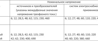
According to GOST 29322-2014, the rated line voltage in three-phase networks should be 400 V, and under normal operating conditions the supply voltage should not differ from the rated voltage by more than +-10%.
Based on this, a drop of 8.43% is justified and complies with the Rules and GOSTs adopted in the Russian Federation.
Calculation of voltage drop for the 1st section
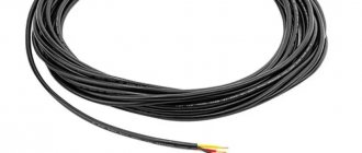
During the examination, the following was revealed. From the transformer substation, located at a distance of 440 m, electricity is supplied to Main Switchboard 2.2 via a cable line consisting of four parallel-connected AVBbShv 4x240 cables, with a total cross-section of 960 mm2.
Internals of main switchboard 2.2. At the top is the input from the TP to the input contactor-protective circuit breaker, to the right are the busbars from the automatic transfer switch (reserve - diesel), below is the output circuit breaker, and the outputs to the Systems.
The maximum calculated load current, according to the passport data, is 240 A for System 12 and 838.1 A for System 14. Therefore, the maximum cable line current is 240 + 838.1 = 1078.1 A.
The total installed power, according to the data sheet, is 316.6 kW for System 12, and 905.5 kW for System 14. Therefore, the total installed power of the entire load is 316.6 + 905.5 = 1222.1 kW.
Let's calculate the voltage drop on the cable line of the 1st section from the transformer substation to the main switchboard 2.2 using the formula:
Δ U=√3 I(R cos φ L+X sin φ L)
Initial data for calculation:
- Maximum current I = 1078.1 A,
- Installed load power 1222.1 kW,
- Specific active resistance of one core R = 0.125 Ohm/km according to the cable manufacturer.
- Specific inductive reactance of one core X = 0.077 Ohm/km according to the cable manufacturer.
- We accept Cosφ = 0.8, then sinφ = 0.6
- Cable core material – aluminum,
- Line length L = 0.44 km.
Substituting the data into the formulas, we find that for one cable the drop will be 239 V, or 57.75%. Then for the existing cable line of the 1st section the voltage drop will be 59.8 V, or 14.43%.
Such a voltage drop in only the 1st section is unacceptable.
This is the basic formula. I did the calculations using a calculator. I checked the received data using the Electrician program (subprogram “Losses”).
In addition, Igor Krivulets (220blog.ru) helped me a lot, for which I thank him very much! At the end of the article there will be a video on the topic of voltage drop.
There are also good books on electrical engineering, download them directly from my blog!
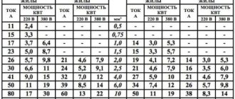
Just in case, a table of active and inductive resistances of aluminum and copper cables of different sections:
Table of active and inductive resistances of aluminum and copper cables of different sections
The result of the survey of the 2nd section (System 12)
After the GRShch2.2 switchboard, the second section of the cable line to System 12, consisting of one AVVG-ng-LS 5×185 cable, 50 m long, goes to the load.
Data for calculation:
- Maximum current 240 A,
- Installed load power 316.6 kW,
- Specific active resistance of one core R = 0.164 Ohm/km according to the cable manufacturer.
- Specific inductive reactance of one core X = 0.077 Ohm/km according to the cable manufacturer.
- Cable core material – aluminum,
- Line length L = 0.05 km.
For an existing cable line, the voltage drop will be 3.67 V, or 0.88%.
The result of the survey of the 2nd section (System 14)
After the GRShch2.2 switchboard, the second section of the cable line to System 14 goes to the load, consisting of three parallel-connected cables AVVG-ng-LS 5×185 with a length of 40 m.
Data for calculation:
- Maximum current 838.1 A,
- Installed load power 905.5 kW,
- Specific active resistance of one core R = 0.164 Ohm/km according to the cable manufacturer.
- Specific inductive reactance of one core X = 0.077 Ohm/km according to the cable manufacturer.
- Cable core material – aluminum,
- Line length L = 0.04 km.
For one cable, the voltage loss will be 10.2 V, or 2.47%. For the existing cable line of the 2nd section of System 14, the voltage drop will be 3.4 V, or 0.82%.
Recommendations for upgrading cable lines
For a given maximum current and line length, a different cable line for Section 1 must be selected because the calculated voltage drop for that section is unacceptable. Based on the preliminary calculation data and the voltage drop data in 2 sections, the voltage drop in the 1st section should be no more than 7.55%.
This level of losses will be provided by a cable line consisting of 8 AVBbShv 4x240 cables connected in parallel. That is, add additional cables (4 pieces) to the existing cables (4 pieces).
As a result, the losses on the cable line of section 1 will be 7.2%, or 29.8 V.
The cable lines of 2 sections do not need modernization.
conclusions
For stable operation of refrigeration equipment, according to its passport data, a voltage with permissible limits of 380 to 415 V is required.
If we take into account the recommendations given, then with an output voltage of the TP of 415 V at maximum load, the voltage loss for System 12 will be 7.2 + 0.88 = 8.08%, or 33.6 V. As a result, at maximum load, the supply voltage of System 12 will be not less than 381.4 V.
For System 14, the losses will be 7.2 + 0.82 = 8.02%, or 33.2 V. As a result, at maximum load, the supply voltage of System 14 will be at least 381.7 V.
Voltage quality measurement results
The measurements were carried out using a HIOKI 3197 , which allows you to take all voltage parameters online.
The device is designed to plot graphs of various power supply parameters in real time. I have already used HIOKI 3197 in voltage quality analysis for problems with refrigerators. If anyone needs such a device, please contact us!
The measurements were carried out at the connection point of the 2nd section of System 14 in different operating modes of the equipment. The 2nd section of System 12 was not examined because it could not be accessed without turning off the power supply to the TP. But since System 12 is low-power compared to System 14, measurements are sufficient to get an overall picture, the results of which are shown in the graphs below.
Voltage monitoring result
Current monitoring result
Explanations for the graphs.
Peak current consumption (switching on the load at 100% power) occurs at 16:56. In this case, the phase voltage (averaged over phases) is 212 V (linear - 367 V), the current is 836 A.
The transformer is idle (the load is completely turned off) at 17:07. In this case, the phase voltage is 238 V (linear - 412 V), the current is 0 A.
System 12 was turned off when measurements were taken.
Based on the results of the measurements, it can be concluded that the maximum total voltage drop for System 14 is 45 V, or 11%.
These measurements confirm the correctness of the calculations and recommendations made.
Photo of connecting the HIOKI 3197 device to the cable line during the measurement process:
Connecting HIOKI 3197 for real-time voltage measurements
Backup power
Backup power in the main switchboard 2.2 comes from a diesel power plant (diesel power plant). Switching is done through the ATS (automatic transfer switch) system.
Backup power supply parameters:
- Maximum power of diesel power plant – 600 kW,
- Cable line – 3 cables AVBbShv 4x240, connected in parallel,
- Cable line length – 250 m.
Based on these parameters, we can clearly conclude that the capacity of the diesel power plant and the backup cable line, taking into account the voltage drop, will be enough for no more than half of the maximum load requirements, which is completely unacceptable.
Therefore, it makes no sense to monitor the quality of food through the diesel power station.
For backup power in this case, it is recommended to use a diesel power plant with a power of at least 1220 kW. The cable line must contain 5 AVBbShv 4x240 cables, in which case the voltage drop to the main switchboard 2.2 will be an acceptable value of 6.5%.
Own needs
Losses in substation power transformers
Own needs are usually classified as a special category, classified as actual losses. In this indicator, it is customary to record the costs of maintaining the operability of the following objects:
- substations with transformers installed in them;
- administrative buildings, auxiliary buildings, etc.
Each item is included in the total amount in the proportion normalized for a given type of consumer.
The most significant contribution is made by district substations, since they house the main service equipment. It ensures normal operating modes of the units responsible for converting electricity, as well as its delivery to the consumer.
Charging room for traction batteries
To record the value of these costs, substations install their own metering devices.
List of consumers traditionally belonging to this category:
- ventilation systems that guarantee complete cooling of a set of transformer equipment;
- heating and ventilation systems for technological premises, as well as lighting networks installed in them;
- lighting devices located in sectors and territories adjacent to substations;
- equipment of premises for battery charging;
- heating systems for outdoor installations (for controlling air switches, in particular);
- compressors and auxiliary mechanisms.
This type of equipment also includes devices and tools used for repair work, as well as for the restoration of auxiliary equipment.
conclusions
As is easy to see from the formulas, the thicker the wire, the lower the voltage drop.
In this case, the voltage drop is inversely proportional to the cross-sectional area of the conductor.
Doubling the cross-sectional area of the conductor approximately doubles the voltage drop across the wires
Another possible solution to the problem may be to increase the voltage value of the current source. If, of course, current consumers allow it.
The voltage drop across the wire decreases linearly with increasing voltage of the current source.
Doubling the supply voltage approximately halves the voltage drop
For example, our low-voltage E27 lamps for 12-24 volts produce the same light from both 12 and 24 volts. And in this case, it makes sense to switch to a 24 volt transformer.
It also becomes clear that for powerful consumers (about 100 watts) very thick wires will be needed.
Commercial component
Lack of control over the operation of metering devices leads to unaccounted for theft of electricity.
First of all, this component concerns the characteristics of metering devices belonging to end consumers (their errors, in particular). To reduce this type of loss, a number of specific measures have been developed and successfully applied in practice. The commercial category includes not only errors when issuing bills to a specific consumer, but also unaccounted for theft of electricity. In the first case, they most often arise for the following reasons:
- the contract for the supply of electricity contains incomplete or not entirely correct information about the consumer and the balance sheet of the facility assigned to him;
- error in specifying the selected tariff;
- lack of control over the operation of metering devices (this case is typical for garden cooperatives and SNT, in particular);
- inaccuracies arising when adjusting previously issued invoices, etc.
Typical errors caused by a controversial determination of the boundaries of the balance sheet of an object are resolved in the manner established by the legislation of the Russian Federation.
The problem of theft is difficult to solve in all civilized countries. These illegal actions are constantly suppressed by the relevant authorities, cases regarding them are sent to local courts. The peak of such thefts traditionally occurs in winter and precisely in those regions of the country where there are problems with centralized heat supply.
This only confirms the interconnectedness of the commercial components of costs for each category of energy resources.
Commercial losses: the main direction of increasing efficiency in the electric power industry
Commercial losses of electricity are considered a difficult value to predict, since they depend on consumers and their desire to deceive the enterprise or the state. The basis of these problems are:
- Seasonal component. The presented concept includes the underpayment of individuals for actually supplied electrical energy. For example, in the Republic of Belarus, there are 2 reasons for the appearance of the “season” - the availability of tariff benefits and payment not on the 1st, but on the 25th.
- Imperfection of metering devices and their incorrect operation. Modern technical means for determining consumed energy have greatly simplified the task for the subscriber service. But electronics or an incorrectly adjusted accounting system can fail, which causes an increase in commercial losses.
- Theft, underestimation of meter readings by commercial organizations. This is a separate topic for conversation, which involves various tricks of individuals and legal entities to reduce electrical energy costs. All this affects the growth of losses.
Main causes of electricity leaks
Most of the energy produced by a transformer is dissipated.
A competent approach to calculating electricity losses involves taking into account the reasons why they occur. When studying the problem, one should separate the sources of unproductive expenses in accordance with the already familiar classification. You should start with the technical component, which is usually associated with the following elements:
- transformers;
- high-voltage cable or overhead line;
- equipment serving the line.
Any power transformer has several windings, the frame of which is mounted on a ferromagnetic core. This is where most of the electricity is lost, transformed into heat (it is then simply dissipated into space).
The amount of losses in various elements of the electrical network is also affected by its operating mode: idle or “under load”. In the first case, they are assessed as constant, independent of internal and external factors. When connecting a consumer, the level of losses depends on the magnitude of the load current in the circuit, which changes every day. Therefore, to evaluate it, static observations are carried out for a certain period (for a month, for example).
Losses in high-voltage power lines occur during energy transportation due to leaks associated with corona discharge, as well as due to heating of the conductors. The category of service equipment includes installations and devices involved in the generation, transportation, as well as in the accounting and consumption of supplied energy. The values of excess losses in this category generally do not change over time or are taken into account through electric meters.
Basic formulas for determining voltage
To calculate the voltage and resistance in a circuit, formulas or ready-made online calculators are used.
Through current and resistance
| Meaning | Formula |
| Basic calculation of voltage on a circuit section | U=I/R, where I is the current in Amperes, and R is the resistance in Ohms |
| AC voltage detection | U=I/Z, where Z is the resistance in Ohms, measured along the entire length of the circuit |
Ohm's law has exceptions to its application:
- When high-frequency currents pass, a rapid change in electromagnetic fields occurs. When calculating high-frequency circuits, the inertia of the particles that transfer the charge should be taken into account.
- When circuits operate at low temperatures (near absolute zero), substances may develop the property of superconductivity.
- A conductor heated by passing currents causes variable resistance to appear.
- When exposed to high voltage conductors or dielectrics.
- During processes occurring in semiconductor-based devices.
- When LEDs are working.
Through power and current
With a known consumer power and current strength, the voltage is calculated using the formula U=P/I, where P is the power in Watts, and I is the current strength in Amperes.
When calculating in AC circuits, a different formula is used: U=(P/I)*cosφ, where cosφ is the power factor, depending on the nature of the load.
When using devices with active loads (incandescent lamps, devices with heating coils and elements), the coefficient approaches unity. The calculations take into account the possibility of the presence of a reactive component during operation of the devices and the cosφ value is considered equal to 0.95. When using devices with a reactive component (electric motors, transformers), cosφ is generally considered to be equal to 0.8.
To check the calculations, it is recommended to compare the result with the standard voltage, which is 220 Volts for a single-phase network and 380 Volts for a three-phase network.
Through work and charge
The calculation method is used in laboratory problems and is not used in practice.
The formula has a form similar to Ohm's law: U=A/q, where A is the work done to move the charge in Joules, and q is the passed charge, measured in Coulombs.
Resistance calculation
During operation, a conductor creates an obstacle to the flow of electric current, which is called resistance. In electrical calculations, the concept of resistivity is used, which is measured in Ohm*m.
| Meaning | Formula |
| Calculation of the resistance of one element | R=U/I, where U is voltage in Volts, and I is current in Amperes |
| Calculation for a homogeneous conductor | R=(ρ*l)/S, where ρ is the resistivity value (Ohm*m, taken from tables of values), l is the length of the conductor section (meters), and S is the cross-sectional area (m2) |
Serial connection
In a series connection, the output of an element is connected to the input of the next one. The total resistance is found using the calculation formula: R=R1+R2+…+Rn, where R=R1+R2+…+Rn are the resistance values of the elements in Ohms.
Parallel connection
A parallel connection is a connection in which both terminals of one circuit element are connected to the corresponding contacts of the other. Parallel connection is characterized by the same voltage across the elements. The current across each element will be proportional to the resistance.
The total resistance is calculated using the formula: 1/R=1/R1+1/R2+…+1/Rn.
In real wiring diagrams, a mixed connection is used. To calculate the resistance, you should simplify the circuit by summing up the resistance in each series circuit. The circuit is then reduced by calculating individual sections of the parallel connection.
The concept of a standard indicator
This term refers to a practically proven and economically justified amount of losses over a certain period of time. When approving the standard, all previously discussed components are taken into account, for each of which a separate analysis is carried out. Based on their results, the actual (absolute) value is calculated and possible options for reducing this indicator are considered.
The normalized value does not remain constant all the time - it is continuously adjusted.
In this case, absolute indicators mean the difference between the power transferred to the consumer and technological (variable) losses. Standard values for the last parameter are calculated using the appropriate formulas.
What are electrical energy losses?
Electricity losses in a broad sense should be understood as the difference between inputs into the network and actual consumption (useful output). Calculation of losses involves the determination of two quantities, which is performed through accounting for electrical energy. Some are located directly at the substation, others at consumers.
Losses can be calculated in relative and absolute values. In the first case, the calculation is performed in percentages, in the second - in kilowatt-hours. The structure is divided into two main categories due to its occurrence. Total losses are called actual and are the basis for the efficiency of the unit.
Who pays for lost electricity?
To determine who should pay for the unproductive costs of electricity in the network, you should take into account the specific situation, as well as a number of additional criteria. When it comes to the costs of replenishing technological losses, their payment falls on the shoulders of consumers - individuals or legal entities.
It is not taken into account directly, but is included in existing tariffs.
When paying electricity bills, each consumer pays the network organization for all kinds of losses in transmission lines and transformers. In the case of the commercial component, the company supplying the energy resource to the client has to pay for any excess of the indicator above the standardized value.
How to use an online calculator?
In the finished table you need to enter data according to the selected cable material, system load power, network voltage, cable temperature and method of laying it. Then click the “calculate” button and get the finished result. This calculation of voltage losses in a line can be safely used in work, if you do not take into account the resistance of the cable line under certain conditions:
- When specifying the power factor, cosine phi is equal to one.
- DC network lines.
- AC network with a frequency of 50 Hz made of conductors with cross-sections up to 25.0–95.0.
The results obtained must be used according to each individual case, taking into account all the errors of cable and wire products.
Be sure to fill in all values!
Ways to reduce losses
It is possible to reduce unproductive expenses by reducing the commercial and technological components of total losses. In the second case, this can be done by taking the following special measures:
- optimization of circuit solutions and operating modes of the electrical network;
- studying statistical data and identifying nodes of maximum loads;
- reduction of the total power pumped through the network due to an increase in the reactive component;
- optimization of transformer load lines;
- updating equipment and applying different approaches to load balancing.
These measures make it possible to significantly reduce total consumption and losses and ensure high quality voltage in the network (it will not “sag”).
Loss reduction methods
Power losses can be reduced by the following methods:
- Increase the cross-section of conductors. As a result, resistance will decrease and losses will decrease;
- Reduced power consumption. This setting cannot always be changed;
- Changing the cable length.
Reducing power and changing line length is practically impossible. Therefore, if you increase the cross-section of the wire without calculation, then on a long line this will lead to unjustified costs.
This means that it is very important to make a calculation that will allow you to correctly calculate the power losses in the cable and select the optimal cross-section of the cores.
Drawing up unbalances in high-voltage and distribution networks
Technical power losses can be identified through another method. It has already been mentioned above - it is assumed that all high-voltage or distribution networks are connected with metering devices. They help determine the value as accurately as possible. In addition, this technique ensures a real fight against non-payers, theft and misuse of energy equipment.
It should be noted that such an approach, despite its effectiveness, is not applicable in modern conditions. This requires serious measures with high costs for the implementation of tying all consumers with electronic accounting with data transmission (ASCAE).
Methods for calculating technical losses at electric power enterprises
Electricity losses in electrical networks are carried out using two main methods:
- Calculation and preparation of loss standards, which is implemented through special software, which contains information on the topology of the circuit. According to the latter, standard values are determined.
- Drawing up imbalances for each element of electrical networks. This method is based on the daily, weekly and monthly compilation of balances in high-voltage and distribution networks.
Each option has its own characteristics and effectiveness. It is necessary to understand that the choice of option also depends on the financial side of the issue.
Actual losses: total
To calculate actual losses, it is necessary to add up the commercial and technical components. However, the actual calculation of this indicator is carried out differently; the formula for electricity losses is as follows:
Amount of losses = (Receipts to the network – Useful supply – Flows to other energy systems – Own needs) / (Receipts to the network – Lossless – Flows – Own needs) * 100%
Knowing each element, the actual losses are determined as a percentage. To calculate the required parameter in absolute values, it is necessary to perform calculations only for the numerator.
Calculation software used
Currently, there is a huge amount of software that calculates the technical loss standard. The choice of a particular product depends on the cost of service, region and other important points. In the Republic of Belarus, the main program is DWRES.
The software was developed by a group of scientists and programmers of the Belarusian National Technical University under the leadership of Professor N.I. Fursanov. The tool for calculating the loss standard is specific and has a number of systemic advantages and disadvantages.
For the Russian market, the RPT 3 software, which was developed by specialists from OJSC Scientific and Technical Center of Electric Power Industry, is especially popular. The software is quite good, it performs the assigned tasks, but it also has a number of negative aspects. Nevertheless, the calculation of standard values is carried out in full.