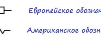
Marking of Soviet resistors
First of all, let's deal with Soviet resistors.
No matter what you do, you cannot escape from Soviet electronics. Therefore, a little theory will not harm you.
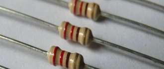
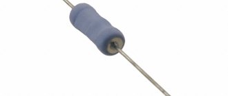
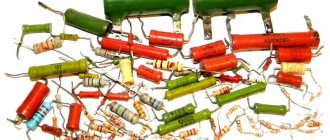
At first glance, we must estimate what maximum power the resistor can dissipate. From top to bottom, below in the photo, resistors by power: 2 Watt, 1 Watt, 0.5 Watt, 0.25 Watt, 0.125 Watt. On resistors with a power of 1 and 2 Watts they write MLT-1 and MLT-2, respectively.
MLT is a type of the most common Soviet resistors, from the abbreviated names M metal-film, varnished , heat -resistant. For other resistors, the power can be estimated based on their dimensions. The larger the resistor, the more power it can dissipate into the surrounding space.
Units of measurement in MLTs - Ohms - are designated as R or E. Kilo-ohms - with the letter “K”, Mega-ohms with the letter “M”. Everything is simple here. For example, 33E (33 Ohms); 33R (33 Ohm); 47K (47 kOhm); 510K (510 kOhm); 1.0M (1 MOhm). There is also a trick that letters can precede numbers, for example, K47 means that the resistance is 470 Ohms, M56 - 560 Kilohms. And sometimes, in order not to bother with commas, they stupidly push a letter there, for example. 4K3 = 4.3 Kilohm, 1M2 - 1.2 Megaohm.
Let's look at our hero. Let's look immediately at the designation. 1K0 or in words “one to zero”. This means that its resistance should be 1.0 Kilohm.
Let's see if this is really true?
Well, yes, everything agrees with a small error.
Characteristics of MLT resistors
A constant resistor is a simple element - it doesn’t have too many parameters. The main characteristics are the nominal resistance and power dissipation.
Dimensions
Its resistance and power depend on the size of the resistor - a large element is able to retain a larger flow of electrons and heats up less. Experienced electromechanics can distinguish a high-value resistor from a low-power one at first glance.
| Type of resistor | Dimensions, mm | Weight, g no more | |||
| D | L | d | I | ||
| MLT-0.125 | 2,2 | 6,0 | 0,5 | 20 | 0,15 |
| MLT-0.25 | 3,0 | 7,0 | 0,6 | 20 | 0,25 |
| MLT-0.5 | 4,2 | 10,8 | 0,8 | 25 | 1,0 |
| MLT-1 | 6,6 | 13,0 | 0,8 | 25 | 2,0 |
| MLT-2 | 8,6 | 18,5 | 1,0 | 25 | 3,5 |
Denominations
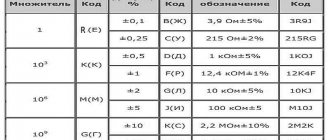
Help: Typical resistor resistance values are standardized - the value is selected from a special series of values, which is a set of values from 1 to 10, and multiplied by 10 to the n-power.
In electrical engineering, series E is used - the nominal resistance of MLT resistors will correspond to the values of series E24 (deviation from the nominal value is no more than 5%) and E96 (deviation from the nominal value is not more than 1%).
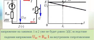
Limit operating voltages
Electric strength is the maximum operating voltage that is briefly applied to the resistor terminals without affecting its performance. It is calculated based on the rated power of the resistor and its resistance using the formula: U=(P×R)/2.
| Resistor type | Rated power, W | Nominal resistance | Limit operating voltages |
| MLT-0.125 | 0,125 | 8.2 Ohm - 3.0 MOhm | 200 |
| MLT-0.25 | 0,25 | 8.2 Ohm – 5.1 MOhm | 250 |
| MLT-0.5 | 0,5 | 1 Ohm – 5.1 MOhm | 250 |
| MLT-1 | 1 | 1Ohm – 10MOhm | 500 |
| MLT-2 | 2 | 1 Ohm – 10 MOhm | 700 |
Reference: Classification of metal film resistances by power dissipation - 0.125; 0.25; 0.5;1.0; 2.0.
Dependence of permissible power on ambient temperature
Depending on the temperature, the same power dissipation can cause significant heating of the resistance and, as a result, destruction of the junction of the resistor with the terminals and local overheating and melting of the resistive layer.
Temperature coefficient of resistance
Under the influence of the flowing current and external temperature, the resistance of the resistor changes - a strong change can disrupt the operation of the circuit. TCR is an indicator of the change in resistance when the temperature changes by 1 degree.
For metal film resistances of TKS at ambient temperature:
- From -60 to +25 degrees – ±0.0012.
- From +25 to maximum:
- up to 10 kOhm – ±0.0006;
- from 11 kOhm to 1 Mohm – ± 0.0007;
- more than 1 Mohm – ± 0.001.
Color coding
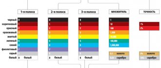
To determine the resistance value of a color-coded resistor, you first need to rotate it so that its silver or gold stripes are on the right and a group of other strips are on the left. If you cannot find a silver or gold strip, then you need to rotate the resistor so that the group of strips is on the left side.
Strip color - coded number: Black – 0 Brown – 1 Red – 2 Orange – 3 Yellow – 4 Green – 5 Blue – 6 Purple – 7 Gray – 8 White – 9
The third bar has a different meaning: it indicates the number of zeros that should be added to the previous digital value obtained.
Strip color – Number of zeros Black – No zeros – Brown – 1 – 0 Red – 2 – 00 Orange – 3 – 000 Yellow – 4 – 0000 Green – 5 – 00000 Blue – 6 – 000000 Purple – 7 – 0000000 Gray – 8 – 00000000 White – 9 – 000000000
It should be remembered that the color coding is quite consistent and logical, for example, green means either the value 5 (for the first two stripes) or 5 zeros (for the third strip).
The sequence of colors itself coincides with the sequence of colors in the rainbow (from red to purple) (!!!)
If a resistor has a group of four stripes instead of three, then the first three stripes are numbers, and the fourth strip indicates the number of zeros. The third digital strip makes it possible to indicate the resistance of the resistor with higher accuracy.
Let's look at a resistor unknown to us.
Basically, there are three, four, five and even six stripes on a resistor. The first strip is closest to the resistor terminal and is made wider than all other strips, but sometimes this rule is not followed. In order not to sift through reference books on the color marking of resistors, you can download many different programs on the Internet for determining the resistor value.
You can also find a very good online calculator on our website - color coding of resistors.
The principle of working with the online service
- The markings are read from left to right. The resistor should be positioned so that the rings are shifted to its left edge. If the dimensions of the part are so small that it is impossible to move the marking to one of the terminals, then the first strip is made twice as wide as the rest.
- The columns in the table correspond to a specific band.
- The lines contain colors.
- To determine the resistance and deviation value for each strip, mark the desired color in the corresponding line.
Resistor marking calculator
I really liked the Resistor 2.2 program. (Or use our online version of the calculator) Even a preschooler can figure out this program. Let's use it to determine the value of our resistor. We drive in the strips of the resistor we are interested in and the program will give us its value.
And at the bottom left in the frame we see the resistor value: 1kOhm -+5%. Convenient isn't it?
Now let's measure the resistance using a multimeter: 971 ohms. 5% of 1000 ohms is 50 ohms. This means that the resistor value must be in the range from 950 Ohms to 1050 Ohms, otherwise it can be considered unsuitable. As we can see, the value of 971 Ohms fits perfectly into the range from 950 to 1050 Ohms. Consequently, we have correctly determined the value of the resistor, and it can be safely used for our purposes.
Let's practice and determine the value of another resistor.
All OK ;-).
Universal color chart
For a detailed study of this technique, you can consider the domestic GOST 175-72. According to the current rules, each color corresponds to a certain number. Silver and gold represent decimal parts.
Using a universal table, color codes are deciphered
The figure shows an example of a specialized program. With the help of such calculators, determining the denomination is simplified. The calculation is performed automatically. To find out the value in digital form, just make marks in accordance with the color of a specific radio component.
Standard series of denominations
In order to select serial products without errors, it is worth recalling the use of special row designations. For E12, for example, the permitted deviation from the nominal value is no more than 10% upward/downward. Standard values (15; 18; 22 and others) are calculated in such a way as to eliminate errors with maximum error. The difference between adjacent positions must be 200% or more compared to the established tolerance.
Errors for other rows “E” are given in the following list (%):
- 192 (0,5);
- 96 (1);
- 48 (2);
- 24 (5);
- 6 (20).
For your information. Products with a minimum deviation from the nominal value of electrical resistance are marked with three significant rings (numbers). Additional bars indicate a multiplier and a certain tolerance.
Marking of SMD resistors
Digital marking
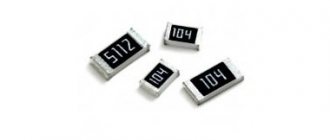
Let's look at the markings of SMD resistors. Resistors of size 0402 (size values here) are not marked. The rest are marked with three or four numbers, since they are a little larger and you can still put numbers or some kind of marking on them. Resistors with a tolerance of up to 10% are marked with three digits, where the first two digits indicate the value of this resistor, and the last third digit is 10 to the power of this last digit. Let's look at this resistor:
The resistance of the resistor shown in the photo is 22x102 = 2200 Ohms or 2.2 K.
Let's check if this is true? We take this tiny SMD component between the probes and measure the resistance.
Resistance 2.18 kOhm. A small error does not count.
SMD resistors with a tolerance of 1% and size 0805 and larger are marked with four numbers. For example, a resistor with the number 4422. This is calculated as 442x102 = 44200 Ohm = 44.2 kOhm.
There are also SMD resistors with almost zero resistance (there is still a very, very small resistance) or simply so-called jumpers. They look more aesthetically pleasing than any wires.
Fixed resistance resistors (fixed resistors).
unchanged during operation.
. Structurally, such a resistor is a ceramic tube, on the surface of which a conductive layer is applied, which has a certain ohmic resistance. Metal caps are pressed along the edges of the tube, to which resistor leads made of tinned copper wire are welded. The top of the resistor housing is covered with moisture-resistant colored enamel.
The ceramic tube is called a resistive element
and depending on the type of conductive layer applied to the surface, resistors are divided into
non-wire
and
wire
.
2.1. Non-wire resistors.
Non-wire resistors are used to operate in electrical circuits of direct and alternating current, in which relatively small load currents flow. The resistive element of the resistor is made in the form of a thin semiconducting film
, applied to a ceramic base.
The semiconducting film is called resistive layer
and is made from a film of a homogeneous substance with a thickness of 0.1 - 10 microns (micrometer) or from
microcompositions
. Microcompositions can be made of carbon, metals and their alloys, oxides and compounds of metals, and also in the form of a thicker film (50 microns) consisting of a crushed mixture of a conductive substance.
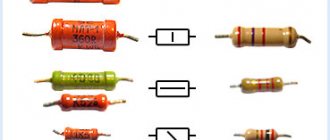
Depending on the composition of the resistive layer, resistors are divided into carbon, metal-film (metallized), metal-dielectric, metal-oxide and semiconductor. The most widely used are metal film and carbon composite fixed resistors. Domestic resistors include MLT, OMLT (metalized, enamel-lacquered, heat-resistant), BC (carbon) and KIM, TVO (composite).
Non-wire resistors are characterized by their small size and weight, low cost, and the ability to be used at high frequencies up to 10 GHz. However, they are not stable enough, since their resistance depends on temperature, humidity, applied load, operating time, etc. But still, the positive properties of non-wire resistors are so significant that they are the ones that are most widely used.
2.2. Wirewound resistors.
Wirewound resistors are used in DC electrical circuits. When making a resistor, a thin wire made of nickel, nichrome, constantan or other alloys with high electrical resistivity is wound onto its body in one or two layers. The high resistivity of the wire allows the resistor to be made with minimal consumption of materials and small dimensions. The diameter of the wires used is determined by the current density passing through the resistor, technological parameters, reliability and cost, and starts from 0.03 - 0.05 mm.
To protect against mechanical or climatic influences and to secure the turns, the resistor is coated with varnishes and enamels or sealed. The type of insulation affects the heat resistance, dielectric strength and outer diameter of the wire: the larger the diameter of the wire, the thicker the insulation layer and the higher the dielectric strength.
The most widely used wires are enamel insulation PE (enamel), PEV (high-strength enamel), PETV (heat-resistant enamel), PETK (heat-resistant enamel), the advantage of which is its small thickness with a fairly high electrical strength. Common high-power resistors are enameled wire resistors such as PEV, PEVT, S5-35, etc.
Compared to non-wire resistors, wire resistors are more stable. They can operate at higher temperatures and withstand significant overloads. However, they are more difficult to manufacture, more expensive and unsuitable for use at frequencies above 1-2 MHz, since they have high intrinsic capacitance and inductance, which manifest themselves already at frequencies of several kilohertz.
Therefore, they are mainly used in DC or low-frequency circuits, where high accuracy and stability of operation are required, as well as the ability to withstand significant overload currents that cause significant overheating of the resistor.
With the advent of microcontrollers, modern technology has become more functional and at the same time much smaller. The use of microcontrollers has made it possible to simplify electronic circuits and thereby reduce the current consumption of devices, which has made it possible to miniaturize the element base. The figure below shows SMD resistors that are soldered to the board from the printed circuit board side.
How to “read” wirewound resistors
Diode color coding
These components are labeled in accordance with the state standards mentioned above. However, to correctly determine the parameters, the following features should be taken into account:
- the maximum number of decimal indicators is 4;
- the last code element is a special property (resistance to high temperature, etc.);
- White color indicates the largest stripe, which describes the products belonging to a certain category (wirewound resistor).
Table of resistors with color codes