An electrical relay is a device in which, when a certain value of the input value is reached, the output value changes abruptly - the output contacts either close - current (voltage) appears in the controlled circuit, or open. Relays are used in control circuits with a current of less than 1 A. The input value of the relay can be mechanical, thermal, electrical and other external influences.
Electrical relays (electromagnetic, magnetoelectric, electrodynamic, induction) that respond to changes in current (voltage) in the control winding (magnetizing winding) have become widespread.
Figure 2.15, a shows the device of the simplest valve-type electromagnetic relay: at a certain MMF in the control circuit, the resulting electromagnetic force F of attraction of armature 3 to yoke 1 exceeds the force of the opposing spring 2. The relay is activated, the air gap decreases, valve 4 presses on the movable contact 5 and presses it with a force F, depending on the value of the air gap at the end of the armature stroke, to the fixed contact 6.
The controlled circuit (control circuit) is closed, the actuator 7 performs the required action. The relay contacts in the initial position can be either open or closed; in the latter case, when the relay is activated, they open and the operation of any devices stops. Initially, open (closed) contacts are shown in diagrams, as shown in Fig. 2.16, a, initially closed (breaking) contacts have the symbol shown in Fig. 2.16, b.
Many electromagnetic relays have several contact pairs, then they are used to control several electrical circuits. Electrical relays perform many functions related to monitoring the operating modes of important elements of the electrical circuit of generators, transformers, transmission lines, and various receivers.
Watch an interesting video about the operation of the relay below:
If the normal mode of one or another element is violated, the corresponding relay activates the equipment, which either restores normal operation or turns off the damaged area. Such relays - protection relays - can “monitor” the current in the circuit (current protection), the voltage in individual sections (voltage protection), changes in power (power relay), changes in the frequency of the current, etc.
Depending on the value or direction of the input quantity leading to the operation of the relay, relays are distinguished: maximum, minimum, directional, differential, etc.
Depending on the response time - the length of time from the moment the control action appears until the moment the relay contacts close - there are high-speed relays ( tav < 0.05 s ), normal ( tav = 0.05-0.25 s ) and time-delay relays (relays time).
If the relay “reacts” only to the value of the input quantity (current) and “does not respond” to the direction of this quantity, then it is called neutral. Relays that “sense” the polarity (direction) of the input quantity (voltage, current) are called polarized.
Relay according to the method of switching on the sensing element
According to the method of switching on the sensing element, primary, secondary and intermediate relays are distinguished.
The receiving element of electromagnetic relays is an electromagnet that converts the control current (voltage) into movement of the armature relative to the yoke.
The sensing elements of other electrical relays can be a magnetoelectric mechanism, an induction system, an electrodynamic mechanism, etc.
The sensing element of the primary relay is connected directly to the controlled circuits. In secondary relays, the sensing element is included in the controlled circuits through measuring transformers. Intermediate relays operate in circuits of actuating elements of other relays and are intended to amplify and convert signals from primary or secondary relays.
Briefly about the main thing
When thinking about good and reliable protection of the electrical circuit, you should pay attention to electromagnetic relays. They can withstand network overvoltage and do not respond to interference. Capable of providing reliable switching on high-power lines. And at the same time maintain its small dimensions.
They have the simplest operating principle, based on creating a magnetic field in a circuit. The latter is responsible for breaking the line in case of danger or for connecting when controlling and adjusting the object. And when choosing between alternating and direct current to operate the device, it is better to choose the latter. If you choose the first, you will have to look for ways to neutralize the strong vibration of the core in the induction coil.
Protection relay
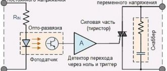
Let's consider the design and principle of operation of electromagnetic current protection relays - maximum current relays. Electromagnetic relays, which have become very widespread, based on the design of the sensing element, are of the valve type and with a rotary armature.
Valve-type relays (see Fig. 2.15, b) are widely used as overcurrent relays. Designations in Fig. 2.15, b: 1 - excitation coil; 2 - yoke; 3 — valve (anchor); 4 - contact group.
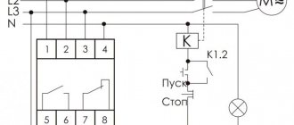
The excitation coil of the RT current relay is connected in series to the controlled circuit (Fig. 2.17)
. When currents / in this circuit exceed permissible values, the force of attraction of the armature to the yoke overcomes the resistance of the spring and leads to the opening or closing of contacts P~ in the control circuit of another device (Fig. 2.17, a, b) - the KM device.
Opening the PT contacts in the KM apparatus (relay) circuit (Fig. 2.17, a) leads to the opening of the KM contacts in the controlled power circuit of the receiver, i.e., the current / breaking circuit (at the same time, the KML contacts that bypassed the “Start” button open). The disappearance of current in the excitation circuit of the current relay Рт leads again to the closure of its contacts Рт (the contacts of this relay are always closed in the absence of current in its winding), but now the excitation circuit of the KM relay is open, since the “Start” button is not turned on and the contacts KMj are open . To turn on the power supply circuit of the receiver, press the “Start” button again, the KM relay will operate and close its contacts KM}.
The “Start” button can then be released, since the KM relay excitation circuit continues to be closed through the KMR contacts shunting the “Start” button. Triggering of the RT relay in the diagram in Fig. 2.17, 6 leads to the closure of the initially open contacts Рт in the KM relay circuit.
The KM relay operates and opens its initially closed KM contacts, which bypassed the resistor R in the receiver power circuit.
In this case, a resistor with resistance R is connected in series with the receiver and thereby the value of the current in the circuit is limited. When the current drops to a normal value, the RT relay will “release” its RT contacts, the KM relay will turn off and the resistor R will be shunted again by the KM contacts.
Relays with a rotary armature are also used as current relays (Fig. 2.18), where an armature 3 made of a soft magnetic material is placed between the poles of the electromagnet /. In the absence of current in field winding 2, spring 4 holds the armature in such a position that contacts 5 and 6 are open, i.e., the control circuit is open. When the current in the excitation winding of the electromagnet reaches a value at which the force tending to turn the armature towards the yoke exceeds the counterforce of the spring, the armature will turn, contacts 5 and 6 will close, and the desired mode change will occur in the controlled circuit.
Another video about the operation of an electromagnetic relay:
The rotation of the driver associated with the spring causes a change in the counterforce of the spring 4 and, consequently, the relay is adjusted to the required operating current.
The operating current values are indicated on the scale. The same relay can be used to control the voltage value on any element. In this case, its field winding, obviously, should have a significantly larger number of turns of wire of smaller diameter compared to the current winding.
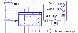
The receiver can be protected from an unacceptable decrease in voltage on it using a minimum voltage relay connected according to the diagram in Fig. 2.19.
If the source voltage corresponds to the required voltage, then the PH relay is activated and its initially open contacts PH close (positions 5 and 6 in Fig. 2.18). By pressing the “Start” button, the excitation circuit of relay K is closed and, through its contacts K, the receiver is connected to the source.
If the source voltage decreases below the permissible limit (which is determined by the setting of the relay Рн), then the counterforce of spring 4 (see Fig. 2.18) overcomes the force of attraction of armature 3 to yoke 1 and contacts 5, 6 open. The excitation current circuit of relay K (Fig. 2.19) opens and the receiver is disconnected from the source.
To protect electrical devices from overload currents, when long-term operation of the device in this mode can cause its failure due to unacceptable overheating, thermal relays are used.
The thermal relay (Fig. 2.20, a) consists of a bimetallic plate 2, which is located in the thermal field of the heater 7, connected in series with the controlled object (receiver), and contacts 4. If the controlled current is greater than permissible, then after some time the bimetallic plate 2 under the influence of excess heat from heater 1, it will bend, since its lower layer expands (elongates) more than the upper one. Plate 2 releases latch 3, which rotates under the action of a spring, and contacts 4 open. The thermal relay switching circuit is shown, for example, in Fig. 2.20, 6, where it is clear that when the thermal relay is triggered, its contacts break the power circuit of relay K and disconnect the receiver from the source. After cooling the bimetallic plate, the relay mechanically returns to its original position.
Control and automation relays (indicating and signaling relays). Electromechanical control relays are low-current devices designed to perform logical and measuring functions in control systems. To characterize the operation of the relay, a number of coefficients are introduced. If we consider the relay as a nonlinear element, the connection between the input /in and output /out quantities is shown in Fig. 2.21, then you can enter the return coefficient Kv as the ratio of the input value /p, at which the relay is activated, to the value of the same value /otp, at which the relay releases.
This coefficient depends on the ratio of the traction characteristic Fx (/в) of the relay (Fig. 2.22) and the characteristic Fnp(lB) of the opposing spring.
At the beginning of the relay actuation process at Iin = Ip, the gap is maximum (l at the beginning) and the force of attraction F1 of the armature to the yoke is slightly greater than the compression force Fnp of the opposing spring. At the end of the relay actuation process, the gap is minimal (/in con) and the force Fx of attraction of the armature to the yoke at the same current/n is already greater than the force F, which is necessary for reliable closure of the relay contacts. The relay will turn off when the current /in is equal to the current /out, i.e. when the force F= F2 becomes less than the force Fnp. The smaller the value DR = Fl - F2 (Fig. 2.22), the higher the return coefficient, the smaller the difference in the values of the operating current /p and the release current /otp. It is possible to ensure a high return coefficient only with relays with a small armature stroke, by reducing friction in the mechanism, and by using ferromagnetic materials with a narrow hysteresis loop. To increase the reliability of relay operation, it is necessary to ensure that the condition /in > /p is met. The required excess of current /in over the value 1p is called the safety factor.
How is the switch indicated on the diagrams?
In order to carry out repair work on a device or assemble a new one, you need to know its exact designation on standard diagrams. The table below contains the main graphic symbols that you will become familiar with.
Table No. 2. Relay designation on diagrams.
| Illustration | Description |
| In the graphic images, the winding is a rectangle with two power outputs. In addition, on diagrams this equipment is often represented by the letter – K. | |
| In the diagram, the contacts of the switching device are designated like the contacts of any other switch. | |
| Polarized switching devices look like rectangles on the diagrams, but only one of the outputs has a dot. Inside the rectangle itself is the letter P, which confirms the polarity. | |
| Often the values of some characteristics are left in the inner part of the rectangle. For example, images with two oblique lines indicate a double coil winding. |
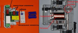
EMR design
EMR is the oldest and most common type of relay.
Such a relay includes the following main elements:
- A coil with a wire wound around a core.
- Anchor.
- Contacts.
- Return spring.
EMR design
EMR works as follows. When voltage appears at the coil terminals, current will flow through it. As a result, an electromagnetic field (EMF) will appear around the coil. Under the influence of EMF, the armature will be attracted to the coil core and move the movable contacts through the mechanical coupling elements. As a result, the electrical circuit will close (open). When the current flowing through the coil drops, the EMF will decrease, and the armature and contacts will return to their original position.
Possible connection errors
In order to avoid errors when connecting relays, it is necessary to consider them in more detail:
- A common mistake is to use a particular relay device in a circuit that is not suitable for it. Due to such negligence, the switch fails after the first operation.
- Another problem is installing a relay that is not designed for the weather conditions of the area. In this case, you should not count on long-term operation of the device.
Important. You can connect the relay using ready-made diagrams. In this case, it is recommended to work carefully so as not to mix up the contacts, otherwise the device will not function.
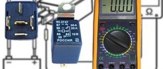
Marking
All data on the technical characteristics of the relay are usually printed on its body. This is not at all superfluous information, since sometimes identical-looking devices have different purposes and capabilities. Moreover, some domestic relays are also called the same, differing only in the so-called passport. In this case, you have to refer to the description.
As for imported relays, of which there are now a large number, the markings on their housing, although they differ depending on the manufacturer, are intuitive. As a rule, there is information about the operating voltage of the winding and the maximum current passing through the switched contacts. In addition, the relay contacts must be marked on the relay body.
Switching contact material
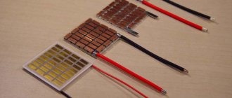
Some relays have a service life of tens of years. At the same time, all its parts experience heavy loads, especially contacts. Firstly, they experience mechanical stress associated with the movement of the anchor. Secondly, they are negatively affected by large load currents. Therefore, the relay contacts must meet the following requirements:
- High electrical conductivity. Provides low voltage drop.
- Good anti-corrosion qualities.
- High melting point.
- Minor erosion. The contacts must be resistant to metal transfer, which is inevitable with constant closing and opening.
All of the listed qualities directly depend on the material used. Let's look at the main metals used to make relays:
- Copper fully meets the requirements, with the exception of corrosion resistance. Therefore, it is often used in relay contacts with a sealed housing. In addition, copper has another advantage - its relatively low cost compared to other metals. Its only drawback is its tendency to oxidize during prolonged use. Therefore, it is used where a short-term operating mode is provided, for example, in the contacts of a turn relay.
- Silver has excellent conductivity and wear resistance. Does not cause sparking when switching inductive loads. However, silver contacts do not have sufficient arc resistance and therefore cannot be used to control loads of significant power. In addition, they are quite expensive. Therefore, the contacts have a combined design - copper with silver coating.
- Tungsten is highly wear-resistant and resistant to high temperatures. Contacts made from it are capable of switching very high currents (tens of amperes).
In addition to the material, relay contacts differ in the switching method.
Switching
In this case, the relay has both normally closed and open contacts. Moreover, there are not four of them in total, as it might seem, but three. The fact is that one of them is common. There are a total of 5 contacts on the relay body (two winding terminals and three switched ones). Due to their versatility, radio elements of this type are widely used. Therefore, most modern relays have switching contacts, sometimes even several groups.