When installing wall-mounted kitchen drawers on a DIN rail, does it need to be cut?
IMHODom › Forums › hands from shoulders › When installing wall-mounted kitchen drawers on a din rail, does it need to be cut?
This topic has 13 voices and 18 replies.
When installing wall-mounted kitchen drawers on a DIN rail, should it be cut into pieces for each drawer, or one piece for the entire length?
It’s just that if there is one for the entire length, then the drawers hang at an angle.
Tilt left, right or forward?
rather to the right and forward
The cabinets are mounted on short sections of these same strips. Their length is approximately 7-10 cm. If there is some kind of defect in the wall with a void inside (well, like a window closed with plywood between the kitchen and the bathroom), then a larger plank is taken, well 10-20 cm. Two drawers are mounted on one plank (one on the right, the other on the left). Then the cabinets are adjusted in height to each other so that they are level. To do this, they twist something with a screwdriver INSIDE the cabinets on a suspension that is already installed at the factory. Then the cabinets are also bolted together; for this purpose, there are holes made at the factory on the side walls.
how complicated everything is. All my life I’ve hung it directly on the wall, it’s like they’re hanging nothing.
Admin Pensioner
As a simpler option: instead of DIN rails, buy 90 degree hooks. (about 80mm long) with dowels. There are grooves in the hangers, on the cabinets, they are about 5mm wide, and the hooks will go into them.
Moscow
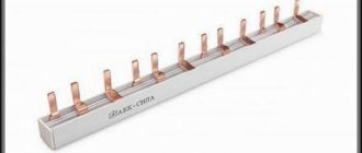
There are slats that are not smooth, but with a notched border between each hole - they are not sawed, but simply broken... the length of each segment is 4-5 cm..
then 7-10 are 2 such sections.. they can be fixed with 2 dowels and hang 2 cabinets.. if you need to hang 1 cabinet in this area, one segment will be enough (the screw should be under the fastening point, and screw it in well - so as not to spinning under load)..
Just in case, I also make a mini-bend of the top corners of a piece of the plank towards the wall - then the cabinet cannot move to the side..
the “standard suspension” has two twisters inside
higher lower - to align the top/bottom of the cabinets and further/closer from the wall - to level the plane of the facades.
“at the factory” or not - it doesn’t matter... you can screw it on yourself and make a hole for the intersection screed (after leveling).
Veteran-3
DIN rail cabinet?! what can’t these Russians come up with...))))
The science
psm, it's not quite a DIN rail. Just similar to her, a little bigger and a little thicker than a piece of iron. Modern fastening of cabinets is designed for it - it allows you to move any side of the cabinet vertically and tilt the cabinet away from the hanging point
When installing wall-mounted kitchen drawers on a DIN rail, should it be cut into pieces for each drawer, or one piece for the entire length?
It’s just that if there is one for the entire length, then the drawers hang at an angle.
Let me tell you how it is necessary and how it is possible
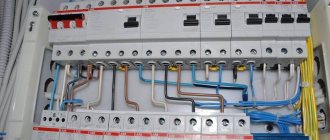
The mounting strip (fastening strip) is indeed similar to a DIN rail. It looks like this (you can see the notches that Akor talked about):
If you do it wisely, then the drawers should be sealed on the back side and the DVPO should be inserted into these grooves. The groove runs at a distance of 16mm from the rear edge of the part. What does this give? This makes it possible to press the entire upper module against the wall to avoid that same tilt. In this case, the mounting strip is broken into sections of 6 centimeters (in the photo above, these are two divisions) and each box is hung separately on two such strips. This is more labor-intensive, but much more aesthetically pleasing and, as they say, straight to the point.
Where is DIN rail used (video)
The modern metal standard DIN rail TN35, most often used in practice, is a special profile with a width of 35 mm. It was developed by specialists from the German Institute for Standardization. Further, it was adopted as the European standard for devices for connecting modular equipment. The DIN designation is translated into Russian according to the name, and sounds like Deutsches Institut fur Normund (German Institute of Standardization). In our country, the production of DIN rails began in 2004. The ETM company can be considered the pioneer. However, their prices were very high. In addition, the company had to adjust the distance between the holes for some time.
DIN rails are made from galvanized steel or aluminum. Some models are perforated along their entire length for ease of distribution into components of the required size.
By profile type
According to the shape of the profile, the slats are divided into the following types:
- Omega-shaped profile, which is the most popular. The products are used for installation of switchboards: installation of automatic protective devices, meters and other necessary devices. The jaws of the slats are curved outward. The width of the device is either 15 or 35 cm. The height of the jaws is made in three standard sizes - 5, 7.5 and 15 mm.
- The C-shaped rail assumes the presence of concave edges 15 mm high. This product is used for mounting hardware clamps and terminal blocks.
- The G-shaped profile is used less often than other slats. Used for installation of some models of devices imported from abroad. It is quite difficult to find a rail of this type in our country.
The ends of the G-type slats are concave inwards, one of them is shorter than the other - the height is 9 and 15 mm. The width of the slats is 32 mm.
By perforation
For its intended purpose, the DIN rail serves as a mounting rail, which is a profiled strip of steel. The horizontal platform in most types of slats is perforated with oval-shaped holes necessary for attaching the product at the point of its installation. The holes are located at a distance of 10-20 mm from each other.
Slats are also available without perforation, the installation of which requires preliminary marking and drilling of holes for fastening at distances in accordance with the required dimensions.
By manufacturing method
According to the production method, products are divided into:
- stamped;
- cast.
Cast slats are highly reliable and can withstand significant loads without losing their shape and properties from their impact.
According to the material of manufacture
Depending on the material used in the manufacture, DIN rails are divided into:
- steel, reinforced with a protective galvanic coating;
- aluminum, lightweight.
By other parameters
DIN rails are also available with reduced profile thickness and width. Other models have special notches, with the help of which the product is divided into pieces of the required length.
Application benefits
The main advantage of using DIN rails is the ease and convenience of installation of modular devices for various purposes in switchboards, regardless of their type of design.
Features of application
DIN rail is a foreign invention that takes its name from the German standard designated DIN 43880-1988. In our country, their use is regulated by GOST R IEC 60715-2003. These products are sometimes called mounting rail. The full name looks like this: “mounting rail for fixing protective devices in low-voltage distribution and control equipment for electrical networks.”
In accordance with this definition, its scope extends to the following cases:
- the need to install electric meters and other types of measuring equipment in the distribution cabinet;
- the need to place protective equipment there (RCDs, automatic circuit breakers, voltage relays, etc.);
- If desired, install special connecting fittings into the cabinet.
The decisive factor determining the capacity of such a rail is the width of the machine module or similar protective equipment installed on its base.
When assessing the width of the machines, they are based on the specific number of protective devices used in the panel, which can have a single-pole or multi-pole design. The second option concerns three-phase networks. In general, its use is limited to this particular set of functions, but in certain situations other directions for using the DIN rail are possible.
Dimensions and installation method
In domestic conditions, standard strips with a profile width of 35 mm (TN 35), having a shelf height of about 7.5 mm, are traditionally used. Different versions of the product may differ in the declared thickness of the profile (1-1.5 mm) and the diameter of the holes filled during perforation (4 or 5 mm). To attach them to the distribution board guides, you will need bolts of the appropriate size.
The installation product is fixed at the two extreme points of the strip in such a way that there are no parts protruding beyond the cut of the guides. That is, the length of the workpiece is selected exactly to size, for which the side excesses are cut off in advance.
In hard-to-reach places with difficult working conditions with modular equipment, it is possible to install holders for DIN rails of a special design. Such guides allow you to rotate them to a convenient angle if desired.
Features of installing a modular socket
Before installing each electrical panel, it is necessary to clearly determine the number and order of arrangement of all modular devices included in its composition. This is connected not only with the need to correctly draw up the general power supply diagram for the apartment, but also directly affects the choice of the switchgear housing.
Each modular element has a clearly defined size, which is regulated by the DIN43880 standard. In accordance with this document, the width of one module is taken to be 17.5 mm.
Depending on the power, today two types of DIN rail sockets are produced. They differ primarily in size.
The design of each such outlet is not fundamentally different from the design of built-in or surface-mounted models. This socket also has two working terminals, to which the phase and neutral wires are connected. Depending on the purpose, this device may be equipped with grounding contacts.
The only feature of such sockets is their clearly regulated shape and size, as well as the presence of a special latch that allows the product to be mounted on a rail.
The figure shows the two most common types of sockets designed for installation on a DIN rail. These models, in addition to their size, are distinguished by the presence of grounding contacts.
Socket without grounding
The width of this device is 1 module (17.5 mm), it is very compact. To install such an outlet you do not have to allocate a lot of space. A similar product is intended for connecting low-power consumers that do not require mandatory grounding, for example, a lamp or soldering iron. Models with rated current of 6 and 10 A are available.
Grounded socket
The socket is somewhat larger, having a width of 2.5 modules. It is equipped with grounding contacts and is intended to supply power to consumers whose metal parts of the housing must be grounded during operation. Such devices include, for example, hand-held power tools. Models are available with a rated current of 10 and 16 A.
Within the two varieties considered, there are a fairly large number of design options for sockets designed for installation on a DIN rail, which are designed to work in different conditions.
Most devices presented in electrical goods stores have a degree of protection of IP20, which is quite enough for installing them in a distribution panel.
As for decoding the designation of the degree of protection of electrical equipment IP, it is very simple. The first digit of the code corresponds to the diameter of the object from which this equipment is protected. The number 2 means that the device body is protected from penetration by objects with a diameter of more than 12.5 mm (human fingers or similar objects). The second digit of the numerical code indicates the degree of moisture protection. 0 corresponds to the absence of any protection against moisture.
If necessary, you can select a product that meets higher protection standards. For example, the Bemis 1/16A grounded socket, which has an IP44 degree of environmental protection, is designed for use in difficult conditions. The body of this product is made of durable plastic and is reliably protected from dust and water splashes. This makes it possible to actively use such sockets in manufacturing enterprises.
https://youtube.com/watch?v=7sz6sf-gUPg
Connection
To connect, you need to determine the power terminals to which the electrical wires are connected (their cross-section should not be less than that indicated on the housing).
Connection and placement can be done in any order.
The connection can be made both after installation of the equipment and before its installation. With the latter connection option, make sure the wires are long enough. The ground wire is usually connected to the panel body, but some electrical circuits provide separate terminals.
An invention of the German Institute for Standardization, DIN mounting rails make it possible to unify and simplify installation in electrical distribution cabinets and automation cabinets.
DIN rail mounting dimensions
There are DIN rails in several sizes. Ω-type DIN rails with a width of 35 mm and a depth of 7.5 (Fig. 1) and 15 mm (Fig. 2) are widely used in electrical engineering.
| rice. 1 | rice. 2 | rice. 3 |
It is on them that standard modular devices are simply snapped on (Fig. 3). To remove the modular device from the DIN rail, use a flat-head screwdriver to release the lock. In addition to the most common 35 mm DIN rails, there are also DIN rails of other sizes: Ω-type DIN rails with a width of 15 mm (Fig. 4), G-type DIN rails (Fig. 5) and C-types with a width of 32 mm .
| rice. 4 | rice. 5 | rice. 6 |
DIN rails come with perforation, which allows you to secure the DIN rail using only a screwdriver and self-tapping screws, and without perforation (Fig. 6). The perforation pitch can be 10-15 mm.
Compliance of the DIN rail with GOST parameters
The DIN rail turned out to be such a successful invention that the DIN rail was adopted as a standard means of mounting both in Europe (EN) and throughout the world (IEC), including Russia (GOST R IEC 60715-2003). GOST describes the standard sizes of Ω-, G- and C-type DIN rails. The dimensions of DIN rails described by GOST are the maximum space occupied by the supporting structure of the rail and fastening means (Fig. 7), the edges of the ribs and technological tolerances (Fig. 8). It is these parameters that are standardized, so the thickness of the DIN rail is not a standardized parameter, but usually ranges from 1 to 1.5 mm.
| rice. 7 | rice. 8 |
The length of DIN rails can also vary. Typically, it is up to 2 m; sometimes manufacturers apply a notch to make it convenient to cut the DIN rail in accordance with the dimensions of the electrical panel.
The materials used are aluminum, galvanized or galvanized steel, and less commonly copper and PVC. When choosing the size and material of the DIN rail, it is necessary to take into account the weight of the equipment planned to be placed on it. If a perforated Ω-type DIN rail with a width of 15 mm made of aluminum is suitable for placing compact terminals, then for mounting high current contactors, power circuit breakers, power supplies, soft starters and frequency converters, you may need steel DIN rails, the thickness of which is 1. 5 mm. GOST provides a methodology for calculating permissible loads for all types of DIN rails.
The safety of an electrical panel or distribution box lies in the strict systematization of all objects, metering devices and circuit components. In order to organize the available space and conveniently place dozens of devices, special din rails are used.
The slats are selected taking into account the sizes, types and weight of the elements being placed, the dimensions of the panel and other parameters that you need to know when choosing and installing the din yourself.
Detachable installation system for electrical equipment
L and n in electrics
The basic element of the Smissline system is plinths in two sizes for mounting six and eight standard modules, which are usually mounted on a standard DIN rail. By connecting the modules together, you can get a base of almost any length. Height limitation – 2 m (height of a standard distribution cabinet).
Conductive bars (10×3mm) are placed in the plinths. The consumer can create a 3-wire (L1, L2, L3), 4-wire (L1, L2, L3, N) or DC power system. In addition to the main power buses, two auxiliary busbars (5x2mm) can be installed in the base to power signal modules or additional contacts of protection devices or, for example, control circuits of contactors.
The busbars are powered through input terminals with a rated current of 160 to 200 A or using protection devices - RCDs, circuit breakers, etc. If the bus system is connected via a protective device, then the entire bus system is also protected.
In the distribution cabinet, the assembled busbar system can be installed either horizontally (traditionally) or vertically. Its vertical placement significantly saves internal installation space and provides power supply to the cabinet both from above and from below. All this, along with the absence of special outgoing terminals (outgoing wires are connected directly to the protection devices), simplifies design and reduces installation time.
Electronic catalogs
- Catalog ABB Basic M, E (modular devices and boxes)
- System pro M compact and other modular devices
- Selective circuit breakers Series S 750 DR
- Surge protection devices OVR
- ESB modular contactors
- E210 Series Switches, Push Buttons and LED Indicators
- Current measurement system CMS
- M2M Performance Indicators
- Smissline - system for detachable installation of electrical equipment
- Electrical equipment for residential premises and offices
Features of choice
When selecting the necessary device, the following nuances are taken into account:
- What is a pulse relay: principle of operation, types, description of devices and connection diagrams. 155 photos of pulse-type relays and video installation instructions
- Photo relay for street lighting - selection criteria, tips for connecting and placing the device (135 photos)
- Pulse protection device: classification, limiter connection diagram and tips for choosing a device (155 photos)
- Particularly popular are 1 mm steel slats with a length of 1 m. This is a universal option that is cheaper than its aluminum counterpart.
- The plates are cut to the size of the shields. The choice is made according to the dimensional characteristics of the box where installation will be carried out. For new fastenings, the size of the strip should include a margin.
- When installing modules for DIN rails, a 10-15 mm plate plus a margin is usually taken.
- If you buy assembled panels, then they already have slats of the required size installed.
The rail is fastened along the edges. Sagging should be avoided; dimensions must clearly correspond to the installation location. If necessary, it is advisable to use special holders.
Strength
As previously mentioned, slats are made from various materials. Each of them has a load limit. When purchasing a slats, consider this factor. For heavy loads, stainless steel slats are suitable.
Aluminum slats can withstand different loads. The load is classified depending on the thickness of the slats.
- The thickness of the 1mm rail is suitable for fastening a single device that is light in weight.
- The 1.1mm rail thickness is intended for several modules.
- The thickness of the slats is 1.4mm-1.5mm and is particularly durable. Can be used for fastening massive devices, switches and high-power devices.
How to place devices?
Automatic switches, meters or buses on a din rail are placed using clamps provided on the body of the equipment itself. Most often there are two or four such clamps: one, two fixed on top and one, two fixed on the bottom.
The installation process itself is as follows:
- Hang the device on the top bracket.
- Place the module for the DIN rail in the required location, moving it along its entire length.
- Use a flat-head screwdriver to pull out the lower clamp and hook it to the edge of the bar.
- Press the clamp back into place (or this will happen automatically if the mechanism is equipped with a spring).
If necessary, you can enhance protection and prevent slipping using some methods:
- purchase and install special fasteners;
- slightly straighten the ends of the strip with pliers.
The same applies to the metal rail itself, because with its help you can greatly simplify the process of assembling the electrical panel, correctly organize the placement of all modules and equipment and significantly increase the safety of any future electrical work.
Popular manufacturers
Many retail outlets offer a chic assortment of electrical devices, including sockets. Having set out to purchase a high-quality socket on a DIN rail, the question arises: what to choose?
Let us note a number of brands that occupy a leading position in the market of electrical goods manufacturers:
- French company Legrand. For more than 100 years, it has been manufacturing information and electrical products.
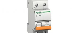
- A large French engineering company, Schneider Electric, which has an excellent reputation as a manufacturer of equipment for the distribution and transmission of electricity.
- The Swedish-Swiss company ABB, which produces automatic protective equipment for electrical networks for various purposes. It is recognized that ABB is the leading manufacturer of such products on the CIS market.
- Italian company Bticino, which produces electrical goods of the highest quality.
The only disadvantage of all the listed manufacturers is their high pricing policy. For those looking for a budget option for electrical goods, the following list of brands is recommended:
- Makel;
- TDM Electric;
- Anam;
- Lezard;
- Wessen;
- GUSI.
These manufacturers produce high-quality electrical products at affordable prices. Thus, when buying a DIN rail socket, you will not incur any special costs, but will be able to ensure ease of maintenance and repair of the electrical equipment of the switchgear.
Like swallows on a wire
Good work is always beautiful work, the results are beautiful to look at. Everything is clean, neat, in its place, well structured and conveniently maintained. For electricians, this result can be achieved by a DIN rail, invented by the Germans, well-known adherents of system and order. They came up with the idea that in electrical panels, cabinets or installation boxes, not every switch, power supply, protective device and the like should be fastened individually, but inserted into the sockets of an installation tape pre-attached to the wall. What brought them to this idea was the fact that current electrical equipment is compact and modular, like all electrical appliances, based on the plug principle: a standard plug that fits perfectly into the socket in any apartment.
An important circumstance: the Germans legalized their invention at all levels, step by step. First there was TN35 - a standard metal rail 35 mm wide with a special profile
It was developed by the German Institute for Standardization (Deutsches Institut fur Normund - DIN). It was subsequently adopted by the International Electrotechnical Commission (IEC) and approved as a European Standard (EN). Since 2004, already in Russia, the TN35 rail was introduced as a national standard by the adoption of GOST R IEC 60715-2003. Rails of reduced format have appeared, both in thickness and in profile width; they are usually used for installing terminals rather than devices. We tell this story so that no one has any doubts, so to speak, about the technical legitimacy of this device: approved and approved at all levels.
The invention of the DIN rail made it possible to radically change the contents of a switchboard with electrical installation equipment. Electrical installation begins with it, whether in large or small volumes, in a private apartment, for example. How to choose it? Let's figure it out.
DIN rail is a generalized name for a complex metal profile perforated along the entire length, which is used for electrical installation. Depending on the required conditions (weight, strength, current strength through the grounding terminals), you select either a galvanized steel rail or an aluminum one. There are solid slats or with regular perforation pitches, and there are pre-notches to facilitate cutting to a certain length.
The profile of DIN rails slightly resembles the shape of a rail, which is why they have a second name - DIN rails. Based on the profile cross-section, there are three types of DIN rails: they resemble letters of the Latin alphabet, which is why they are marked as such - Ω, G and C type.
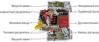
For fastening various elements of modular equipment in installation boxes, electrical cabinets or panels - RCDs, circuit breakers, etc., there are special jaws in the cross-section of the profile.
How to choose the right electrical panel. shield modules
Distribution transformer substation. rp in electrical what is it. What is RP in electrical engineering?
When choosing an electrical panel, in addition to the design (internal, overhead) and the material from which it is made (plastic or metal), an important criterion is its dimensions, or rather the number of panel modules.
A module in a panel is considered to be one single-pole circuit breaker - an automatic circuit breaker, with an average width of 18 mm.
In a word, the maximum possible number of installations of single-pole circuit breakers in a switchboard is the number of switchboard modules.
Therefore, when purchasing a shield, it is necessary to at least approximately determine the modular elements of the shield - automatic machines, RCDs, meters, etc. and their quantity.
Here are the approximate numbers of spaces (modules on a DIN rail) for the main modular elements:
| Single-pole circuit breaker – 1 module |
| Single-phase two-pole circuit breaker – 2 modules |
| Three-pole circuit breaker - 3 modules |
| Single-phase RCD (Residual Current Device) – 3 modules |
| Three-phase RCD – 5 modules |
| Three-phase differential circuit breaker – 6 – 8 modules (depending on the manufacturer) |
| Modular electricity meter on DIN rail – 6 – 8 modules (depending on manufacturer and design) |
| Modular socket for panel on DIN rail – 3 modules |
| DIN rail terminal – 1 module |
| Modular bus for PE conductor DIN rail – 5 modules |
It is better to buy a shield with a small reserve in terms of the number of modules - you should not buy it “back to back”. For example, if the total number of modules is 12, then it is better to purchase a shield for 16 modules. This will provide the necessary reserve in case of changing the wiring diagram or adding new “points”.
If the panel is not completely filled with modular elements, in order to prevent foreign objects from entering the electrical panel, you can use special plugs for panels for empty modules. This will add greater aesthetics, improving the appearance of the shield.
Replacing the circuit breaker in the panel
If you open the electrical panel cover, you will see that all the modules are fixed on a metal strip called a DIN rail. The width of the plate is 3.5 cm, each module occupies 1.75 cm.
To install you will need the following tool:
- pliers;
- screwdrivers - Phillips and straight;
- cable cutting tool, such as wire cutters;
- indicator screwdriver;
- stripper for removing insulation;
- crimper for multi-core cable only.
The first thing you should always do before any manipulation in the electrical panel is to turn off the power and make sure that no one accidentally connects the power during operation. To be on the safe side, use an indicator screwdriver and check that there is no voltage.
Next, take the circuit breaker you purchased in advance and attach it to the DIN rail so that it fits in line with similar devices. If there is free space left at the edges, then it is better to fix the module with special stops - metal brackets with screws.
Installation does not require special fasteners, since the latch is located directly on the device body; just lean it against the rail and press a little. To remove a failed device, you will have to loosen the latch with a screwdriver
Connecting elements with several poles has differences:
- 2-pole - left side: top - phase, bottom - phase of the circuit; right side: top and bottom – zero;
- 3-pole - upper parts - phases in order, lower parts - phases of the circuit in the appropriate order;
- 4-pole - like 3-pole, but the rightmost module is zero.
As you can see, the main connection principle is that the input is connected to the upper terminals, the output to the lower ones. The wires are usually routed into the panel. For ease of use, they are grouped using ties.
It is important to correctly distribute the cable connection locations. For single-pole devices: the phase coming from the RCD or input device is connected to the upper terminal, the circuit phase to the lower (+). Having stretched the ends of the wires to the corresponding terminals, position them freely, without tension, and remove the excess with wire cutters
Use a construction knife or stripper to remove part of the insulation - the length of the exposed wire is about 1 cm
Having stretched the ends of the wires to the corresponding terminals, position them freely, without tension, and remove the excess with wire cutters. Use a construction knife or stripper to remove part of the insulation - the length of the exposed wire is about 1 cm.
If you use a handy tool, try not to damage the cable in the transverse direction, so as not to cause a crease.
When stretching the wires in the shield, try not to bend them, do not make as many turns and creases as possible, and also do not stretch them like a string
The phase connection can be equipped using a comb - a special bus with the required number of poles. Instead of a comb, homemade jumpers made from PV3 wire are also used.
Two wires cannot be placed in one terminal, so they must be crimped with an NShVI tip.
Stranded wires must be crimped - attach the NShVI tip. The tool at hand is not suitable, it is better to use a special device that resembles wire cutters - a crimper
We insert the prepared wires into specially designed holes.
After the wires are stripped and inserted into the terminals, they must be secured by carefully tightening the fasteners with a screwdriver
According to the rules, the device must be marked to indicate its belonging to a specific circuit. Similar markings should be present on the protective cover of the shield.
Auxiliary elements and accessories
The accessories for the new System pro M compact range are universal: they fit all modular switches of the S200 and F200 series, as well as
RCBO series DS200, which allows you to effectively manage existing material resources.
The range is quite wide and includes auxiliary and signal contacts, remote releases and automatic reclosers, allowing the creation of various hardware configurations.
In all these configurations, auxiliary elements are connected without the use of any adapters. This increase in the efficiency of circuit breakers and RCCBs allows the use of innovative and integrated solutions in all cases.
Accessories for electrical installation (busbars, bus terminals and feeder terminals) allow connections to be made according to any scheme). The range of standard accessories (marking sets, terminal covers) allows us to satisfy all the requirements of electrical installation customers.
For circuit breakers S200 series, RCBO series F200, RCBO series DS200, DS201/DS202C
For RCBO series DSH941R
For circuit breakers of the S280 UC and S800 series
How to install?
The instructions for installing the din rail are simple:
Determine the location for mounting the strip (it is important when organizing the space in advance and visually plan the location of all elements of the system in order to avoid confusion, clutter and unnecessary holes in the panel wall). Measure the distance and, if necessary, cut the required length. Mark the places of fastenings on the wall of the shield and the rail (one fastening for every 7-10 cm is enough). If the profile is cast, use a drill to make holes on the surface. Attach the rail to the wall of the shield. Secure with self-tapping screws or bolts. Check the reliability of the fastenings.
Equipment on DIN rail
: reliable circuit breakers and residual current device (RCD) for DIN rail mounting
: AC/DC-DC voltage converters in a design for mounting on a DIN rail
For fastening electrical installation equipment
Modern manufacturers of electrical equipment already provide for the presence of a DIN rail in the switchboard. However, if necessary, it is quite easy to install it in any desired place. For this purpose, the profile of the rail is perforated with holes, thanks to which it can be attached to the plane with bolted connections or self-tapping screws. You just need to take into account the width of the machines that you will mount on it in advance, before installing the rail, so that they don’t feel “crowded”! It is better to cut a DIN rail with a grinder, but a hacksaw can also handle this.
Modern apartments are full of electrical appliances and all sorts of devices, so an electrical panel can occupy a wall area of about a square meter, accommodate a meter, a dozen circuit breakers, a zero operating and protective busbar and other important elements. But when they are compactly “attached” to a DIN rail in a secluded place, the interior of the apartment is not disturbed and no inconvenience is created for residents.
You have secured the tape, now you need to “attach” all the pre-prepared devices to it. In the modern world of electrical engineering, they are fortunately unified. And since all the elements of modern automation are adapted for DIN rails, it is very easy to “seat” them on it - press the sponge on the machine with a flat screwdriver, then lightly move, click - and that’s it, the machine is in its place. It only takes a few seconds to install one module; it’s not like installing screws into a wall!
By the way, it is much easier to maintain such a line of instruments and devices. To replace the machine on standard DIN rails in electrical panels, you just need to loosen the screws securing the wires on the terminals to disconnect them, after which the device lock moves down and the machine is removed from the rail.
Our consultants will advise you on all the other details when choosing the DIN rail you need so much, and electrical installation will become simple, convenient and enjoyable for you, just like when constructing a ship from a children's set of LEGO elements. Good luck to you!
An invention of the German Institute for Standardization, DIN mounting rails make it possible to unify and simplify installation in electrical distribution cabinets and automation cabinets.
DIN rail mounting dimensions
There are DIN rails in several sizes. Ω-type DIN rails with a width of 35 mm and a depth of 7.5 (Fig. 1) and 15 mm (Fig. 2) are widely used in electrical engineering.
| rice. 1 | rice. 2 | rice. 3 |
It is on them that standard modular devices are simply snapped on (Fig. 3). To remove the modular device from the DIN rail, use a flat-head screwdriver to release the lock. In addition to the most common 35 mm DIN rails, there are also DIN rails of other sizes: Ω-type DIN rails with a width of 15 mm (Fig. 4), G-type DIN rails (Fig. 5) and C-types with a width of 32 mm .
| rice. 4 | rice. 5 | rice. 6 |
DIN rails come with perforation, which allows you to secure the DIN rail using only a screwdriver and self-tapping screws, and without perforation (Fig. 6). The perforation pitch can be 10-15 mm.
Compliance of the DIN rail with GOST parameters
The DIN rail turned out to be such a successful invention that the DIN rail was adopted as a standard means of mounting both in Europe (EN) and throughout the world (IEC), including Russia (GOST R IEC 60715-2003). GOST describes the standard sizes of Ω-, G- and C-type DIN rails. The dimensions of DIN rails described by GOST are the maximum space occupied by the supporting structure of the rail and fastening means (Fig. 7), the edges of the ribs and technological tolerances (Fig. 8). It is these parameters that are standardized, so the thickness of the DIN rail is not a standardized parameter, but usually ranges from 1 to 1.5 mm.
| rice. 7 | rice. 8 |
The length of DIN rails can also vary. Typically, it is up to 2 m; sometimes manufacturers apply a notch to make it convenient to cut the DIN rail in accordance with the dimensions of the electrical panel.
The materials used are aluminum, galvanized or galvanized steel, and less commonly copper and PVC. When choosing the size and material of the DIN rail, it is necessary to take into account the weight of the equipment planned to be placed on it. If a perforated Ω-type DIN rail with a width of 15 mm made of aluminum is suitable for placing compact terminals, then for mounting high current contactors, power circuit breakers, power supplies, soft starters and frequency converters, you may need steel DIN rails, the thickness of which is 1. 5 mm. GOST provides a methodology for calculating permissible loads for all types of DIN rails.
What sizes can DIN rails have?
All DIN rails have received standard sizes; they are never produced differently. Dimensions are determined according to the following state standard GOST R IEC 60715-2003, the width in this case can be:
It is worth noting that the omega din rail can have three sizes, because it is universal and is used everywhere. Find out how to take readings from a two-tariff meter.
The minimum length of the DIN rail is 7.5 cm and can accommodate one circuit breaker. The maximum is 2 meters, this length is enough to install 4 shields.
There are still slight differences in the manufacturing method; the planks can be:
- With holes.
- Solid.
The former make it possible to simplify the installation process; just screw the rail into the finished holes. The distance between the holes is 10-20 mm, which can be called optimal.
Cast (solid) ones are considered more reliable; even under heavy loads they do not bend. Even several machines can be installed on such DIN rails. This is how you can mount all devices during electrical installation.
Photo of din rails
Quick installation of electrical equipment - only on DIN rails!
We offer perforated slats:
- 75 mm;
- 300 mm;
- 500 mm;
- 1000 mm;
- 2000 mm.
These are mounting rails made of Omega profile steel with a width of 35 mm. The model was originally developed in Germany and was called DIN rails (DIN - Deutsches Institut fur Normund - German Institute for Standardization). Since 2004, according to GOST R IEC 60715-2003, it has been the standard mounting profile in Russia.
Usage
Mounting mounting DIN rails are designed for installation of modular electrical equipment.
Used for fastening:
- circuit breakers;
- differential automatic machines;
- electricity meters,
- relays, contactors and starters;
- cross-modules and terminals;
- electrical outlets;
- switching equipment.
Using products of this type, equipment is installed in electrical panels, cabinets and installation boxes. The use of DIN rails and the compact dimensions of electrical equipment and products make it possible to place a larger number of equipment in standard housings. This saves installation space, and ease of installation saves time.
Classification
Dinreyks differ in:
- material of manufacture (steel, aluminum);
- length (from 75 to 2000 mm);
- presence of perforation (solid, perforated);
- profile thickness (from 0.8 to 1.5 mm);
- profile shape (omega, G-rail, C-rail).
Assortment presented
In the 220pro store you can buy galvanized steel DIN rails made in Russia and Italy. Profile width 35 mm, height 7.5 mm, Omega type.
Depending on the thickness and length, products are divided into several groups according to load.
For light loads
Galvanized steel - 0.8 mm thick, aluminum - 1 mm, length 75-100 mm. Purpose - for fastening individual elements (automatic machines, RCDs, power supplies).
For medium loads
Steel - 0.8 mm, aluminum - 1.1 mm, length 300-1000 mm. Used for mounting automatic machines, RCDs, power supplies, cross-modules, relays and modular switching equipment.
For increased loads
Steel - 0.8 mm, aluminum - 1.4 mm, length 500-1000 mm. For fastening any type of product: automatic machines, automatic devices, RCDs, frequency converters, contactors and starters, power supplies, cross-modules, relays, power circuit breakers.
For maximum loads
Steel - 1.0 mm, aluminum - 1.5 mm, length 1000-2000 mm. Used for installation of heavy equipment: frequency converters, contactors, soft start equipment, power circuit breakers. The best option for professional installation, with a minimum amount of trimmings.
Different types and additional accessories
In addition to the standard width of 35mm, smaller slats of 15mm with a height of 5mm are available. They are used for installing terminals and other light electrical installation products.
A dinrail holder (bracket) is used as an additional accessory. Installing the holder allows you to “plant” the rail at an angle, turning the lower side “facing” the master conducting the work. When attaching terminal blocks or cross-modules to such an inclined DIN rail, an electrical installer gets convenient access to groups of contacts. This makes it easier to connect cables, especially when distributing one power supply to a group of consumers.
Advantages of using DIN rails:
- standard sizes (suitable for all types of equipment and electrical products);
- safe installation of open electrical wiring;
- suitable for electrical panels, boxes;
- high speed of installation of individual modules on the rail (3-5 seconds);
- quick installation and dismantling of equipment;
- perforation for easy screw mounting;
- notches along the length of the slats for cutting to size;
- installation of a large number of equipment in a small area, without loss of connection quality;
- affordable prices;
- compliance with GOST and IEC requirements.
Very often, when carrying out electrical work, the need arises for high-quality fastening of any electrical devices. DIN rails are widely used as fastening materials. However, many people do not know what it is and what a DIN rail is for.
Manufacturing materials and load characteristics
The material from which a particular DIN rail is made must be suitable for its purpose. This means that it is necessary to take into account the expected loads, depending on which steel or aluminum products are selected. The first of these samples are more durable in their structure and can withstand extreme loads with a minimum strip thickness of only 1 mm.
By critical or extreme loads we mean the situation when large devices such as frequency converters, powerful magnetic starters or three-phase power circuit breakers are mounted on the rail.
Aluminum slats are capable of “holding” maximum stresses of mechanical deformation only with a thickness of 1.5 mm. Accordingly, the range of power and protective equipment placed on them will be significantly limited.
Load characteristics
Steel rails with a thickness of 1.0 mm can withstand maximum loads and have no restrictions on installation
. Since a typical DIN rail is produced as a profile product, it can withstand greater deformation loads than a metal plate of the same size. Typical load characteristics of DIN rails are standardized by current standards for a number of characteristics, including the type of metal. Aluminum strips are available in the following versions:
- 1 mm thick slats designed for installation of single modular devices: circuit breakers, RCD units, power modules;
- 1.1 mm strips, designed for installation of single devices placed in several rows;
- the same products, but with an indicator of 1.4 mm, designed for modular equipment of any class and weight.
All these products are cut into pieces of the required length before installation.
The kit may include steel slats with a thickness of 1.0 mm, the load capacity of which is similar to an aluminum rail with a thickness of 1.5 mm. They can withstand maximum loads without restrictions on weight and number of seats within the permissible size. In addition, manufacturers of switchboard equipment often equip distribution cabinets with non-standard profile rails.
How to use it in electrical
This rail is very popular these days, and therefore most of all panels have a compatible design, as well as other electrical equipment with ready-made mounts. And, as already noted, the main advantage is convenience. This is reflected not only during installation, but also during the maintenance or replacement of equipment.
Installing the rack
First of all, you need to understand how to install the rail. Installation of the strip is carried out as follows:
- Determine the location. It is necessary to take into account not only the profitability of the current situation, but also its strategic benefit, so that in the future there will be no need to reassemble the entire structure.
- Select the required distance for the screws if the structure does not have factory perforations. If you have extra space, it is recommended to take a plate with a reserve. The unused portion can be folded over to fit into the desired space.
- Fix the bar and check its reliability.
Now that the main structure is ready, all the necessary electrical elements can be placed on it.
Installation of the machine
To confirm the mounting on a DIN rail, let’s look at how to fix 1 machine:
- Check the integrity of the installed strip. By default, solid ones are considered the most durable, because the holes are made personally by the builder.
- Hook the machine with one edge on the upper or lower part and press on the opposite side to fix it. It is imperative that there is a click, as it informs that it is securely fastened. In addition, it is recommended to check the clamp before purchasing.
- Ready. The installation is now complete and, thanks to the design, the machine can move freely left and right if necessary.
As follows from the instructions, the fasteners are really simple and can save as much time during replacement and maintenance as during the initial installation.
Modules
In cases where the entire structure has been successfully installed and none of the required minimum is needed, it can be improved with additional modules. They are optional, but will be very useful for those who want to spend a little of their time. So, these can be distinguished:
- Limiter. It is necessary in cases where the movement of the machines is not needed and will become more of a problem than a useful function. Installation is possible as long as there is free space.
- Rosette group. Only professional builders or those who see the point in this will need it. This is far from a necessary improvement, but quite useful if you know why to use it.
- Voltammeter. Allows you to monitor power consumption in real time. Useful in cases where you need to keep records.
- Distribution blocks. Needed for power distribution. The three-phase shield is of particular importance.
- Counter. Thanks to it, you can track the total shield consumption. The only problem may be the size, since even compact ones are often large.
However, you should always remember that the distinguishing feature of modules is their versatility. Therefore, if there is a possibility that the installed innovation cannot be promptly dismantled in the future, it is recommended to refrain from using it.
Knowledge about slats is not difficult to access and non-specific - it is available to everyone. However, such simple information about the types and methods of fastening will save time and money on repairing or building your own home.
Types of din rails
Mounting rails are produced with three types of sections:
- The most common is TH 35, which resembles the Greek letter Ω, after which it is sometimes called the omega profile. 35 is the width of the element in millimeters. Rarely, there are omega profiles with a width of 15 mm (TN15).
- “C” type profiles are quite common. Unlike omega, their edges are curved inward and form an unfinished rectangle.
- The little-known “G” profile differs from the previous one in that the cross-section of one edge is larger than the cross-section of the other: 15 and 9 mm, respectively. The profile width is 32 mm.
The slats can also be solid or perforated. In the latter, the wall along its entire length has a number of holes: round or oval-shaped. Perforation is used for connection with other profiles, for fastening to the walls of electrical cabinets, boxes or any other structure. Each type of profile has modifications provided for by GOST or carried out on individual orders.
What are they?
Types of din rails are determined by different installation conditions and profile capabilities, represented by the following classification:
According to the section configuration
The G-type is a "G" shaped rail where one curved end is shorter and lower than the opposite edge. It is rare to find such a profile on the domestic market, since it is designed for installation of equipment of European standards.
The C-type is symmetrical and more common. The edges of the rail are equally curved, which provides reliable fixation for terminal blocks and clamps of other devices.
Omega-type has a completely different cross-section, similar to the Greek letter “omega”: the ends of the bar are sharply bent in both directions from the rail, forming peculiar “ears”. This design is adapted to almost all electrical elements and devices.
According to the presence of holes for fastenings
Perforated ones have holes approximately every centimeter, which greatly simplifies the process of installing the slats.
- according to the material of manufacture:
- made of aluminum;
- made of stainless steel (more common).
Item Description
So, din rail is a generalized name for a metal profile that is used in electrical engineering. This rail can be galvanized steel or simply aluminum.
It all depends on parameters such as:
- weight;
- strength;
- the strength of the current passing through the ground terminals.
The lath can be either continuous or with a regular perforation step. In addition, there are options with preliminary notching, which greatly facilitates cutting to a certain length.
The very origin of the abbreviation “din” is very simple - it is an abbreviation for the German Institute for Standardization: Deutsches Institut fur Normund. To be fair, it is worth noting that this abbreviation applies not only to rails, but also to other products - connectors, fasteners, etc.
About the installation method
Let us briefly consider the DIN rail mounting method. In cross-section, it has protrusions along the edges. They are designed to hold the device, which is installed on the rail. But at the same time it can be moved relatively freely along it. If such “freedom of action” is not welcomed, then it can be completely eliminated. To do this, you simply need to install special locking elements on the sides of the device, which are also designed for installation on DIN rails.
It is worth noting that in panels that are used for mounting modular equipment, fixation is often performed by creating external holes in the cover, taking into account the actual number of switching equipment. That is why the windows for the outer part of the equipment do not open completely. Some of them are usually covered with curtains, which can be easily removed if necessary. If it so happens that there is less equipment in the panel than could be installed, then all the free spaces that remain are closed with special plugs.
It is worth adding that all modular machines, circuit breakers and RCDs are equipped with special latches. They are designed to hold the element on the DIN rail. To install, the upper groove of the device is fixed on one of its lower edges. In this case, the lower edge of the device is pressed against the rail with slight force until an obvious click is heard.
If the element needs to be removed, you will need a flat-head screwdriver. With its help, you need to carefully move the latch down and remove the device from the groove. It is worth adding that there are elements of equipment in which the latch is fixed in the open position.
What can be installed on a DIN rail?
In addition to protection devices, other elements that are standardized for it can be installed on the DIN rail. These can be electricity meters, relays, automation devices, terminals, signaling and control devices, and zero buses. Many elements of electrical circuits have double fastening points. Due to this, they can be installed both on a DIN rail and on a regular classic surface.
Briefly about the types
It would be wrong if we did not mention that DIN rails come in different types. The most common type is the TN-35-7.5 rail. How to understand these numbers? Very simply, the rail is thirty-five millimeters wide and seven and a half high. There is also another modification - with a height of fifteen millimeters, that is, the TN-35-15 DIN rail. This option is quite often used in wall-mounted and floor-mounted panels. It is worth noting that such slats are also called Ω-type slats. It’s easy to understand where this name comes from if you carefully examine this element in profile.
If we talk about the length, then according to the standard it is two meters. But this is not always convenient, so in most stores DIN rails are sold in pieces of twenty centimeters.
Specifications
The product material is steel with zinc or anodized coating, as well as aluminum alloys.
The slats can have different lengths, depending on the manufacturer. In addition, some types have transverse notches. The spacing with which they are located corresponds to the standard width of various electrical boxes. Such cuts allow you to accurately break off a part of the required length without using a grinder or a hacksaw.
When planning the placement of devices, they proceed from the standard of their width, which allocates 18 mm to the distance between the centers of adjacent devices. The standard pitch between slats is 125 mm. Companies that manufacture boxes for mounting devices use these dimensions as a guide when placing mounting holes for DIN rails.
The accuracy of profile manufacturing, dictated by DIN, is ±0.04 mm.