It is the average voltage class of 6-10 kV that accounts for the main share of emergency shutdowns. Old 6-10 kV power lines made with bare wires are primarily susceptible to the influence of weather factors such as wind and ice. And the use of self-supporting wires with protective insulation can significantly improve their safety and reliability characteristics.
When using SIP-3, several parameters are reduced at once:
- interfacial distance
- width of cleared forest clearing
- space when arranging distribution units at a substation
All this is very beneficial from an economic point of view.
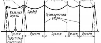
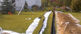
Stages of installation of power line towers
Even at the stage of preparatory work, the power line route is being laid: cleaning the route, leveling the ground and other work.
The route markings are carried out strictly in accordance with the project. When marking, the installation locations of the supports are noted, as well as their delivery to the installation sites. Depending on the design of the supports, they can be supplied disassembled or assembled. The disassembled supports are assembled near the installation site. The required traverses and other linear equipment are hung on the assembled support.
Before assembling the supports or in parallel with the assembly, pits or pits are dug to install the supports. The design of the pits and the dimensions of the pits are also specified in the project. For main power lines and overhead power lines, pits and pits are not dug manually. Drilling rigs are used for this.
Metal supports are placed on pre-made concrete foundations. Wooden supports and reinforced concrete supports for 0.4-6 kV power lines are installed without a foundation. To strengthen the stability of the support, a transverse console is placed at the end of the support in the ground (though not always). For 6-10 kV power lines, they are installed without a foundation, but with the surface of the support being poured with concrete. Power transmission line supports of 35-500 kV are installed with a cover at the end of the support dug into the ground (to strengthen the support) and pouring the support in the ground and the base of the support with concrete. Exceptions may be support trusses in the shape of the letter “P”.
a-Intermediate support; b- anchor support with a strut, placed at angles of rotation of power lines from 20 to 90 degrees. 10 Support, 5-strut (sub support)
The usual design of pits for wooden and concrete power transmission line supports up to 1 kV are cylindrical in shape, 1100-1500 mm deep and 100 mm wider in diameter than the size of the support. Such pits are made using drilling rigs.
Note: In cramped conditions, as well as with small volumes, a hole for support can be dug manually. The profile of the pit should not be cylindrical, but stepped.
Rolling out
Before you begin rolling, temporary rolling rollers should be placed on the supports, which may differ in design and have one (A), two (B) or four (C) support rollers.
As for technological solutions to the problem, there are two of them:
- Using fixed rolling equipment such as jacks, trestles and special machines. This technique is justified when laying short lines, in the area of which the risk of damage to wires is minimal.
- Using mobile means of mechanization of cable conveyors, sleds, carts, etc. This technology has proven itself well when laying long-distance overhead lines. It minimizes the risk of cable damage.
Technology for installing supports using cranes
The technology for installing supports using the first three mechanisms is basically the same. The assembled support is laid along the axis of the overhead line. The center of gravity of the support is 1500 mm from the middle of the pit. The sling is attached to the support above its center of gravity. The second end of the sling is attached to the crane hook. The support rises. To hold it, retaining slings are attached to it along the length of the support. They are held by hands, if the support is small, or by transverse winches.
The raised support, sufficiently 20-30 cm from the ground, is directed into the pit and installed, securing the vertical position with temporary supports or guy wires.
Heavy rack supports (up to 25 meters weighing up to 7000 kg) are installed with a special installation machine, K-LEP-7.
Tension and fastening
Before installing the wires on intermediate supports, they must be tensioned so that they do not touch the ground or other objects and do not sag beyond the permissible limits. For this, it is possible to use various devices, starting with manual pliers and paws, and ending with complex automatic mechanization systems. Stretched electrical wiring:
- Attached to anchors.
- Connect with garlands of insulators.
- Fasten to pre-prepared fastening points.
Installation of supports by crane and tractor
Installation of supports using a crane and tractor has two options:
- Installation by stationary crane and tractor;
- Installation by tractor and crane on a wheeled base.
Installation by stationary crane and tractor
- The support is placed along the axis of the overhead line. Traction cables are attached to the bottom and top of the support;
- The lower cable is attached to the tractor winch. The crane stands at the pit and lifts the support above the ground. In this case, the tractor winch holds the bottom of the support. In this “suspended form” the support is lowered into the pit;
- The lower cable is detached from the tractor winch. Now the upper cable is attached to the winch, which begins to tighten;
- When the crane cable weakens, it is unfastened, and the support is held in place by the tractor and two side winches with temporary braces.
Installation by tractor and crane on wheel base
With this setup, things happen a little differently. The tractor is placed across the road, a meter from the pit. The support is laid along the route at a distance of 1500-2000 mm from the edge of the pit. The support is crushed by the crane and held in place by the tractor. Raising the support, its edge is installed in the pit. The tractor increases the tension of the support, while weakening the crane cable. When the entire load is transferred to the tractor, the crane is disconnected and moved to a safe distance. The final lifting of the support is done by a tractor.
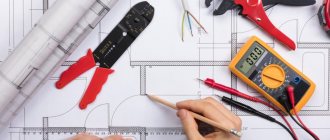
Preparation
The thoroughness and quality of preparation has a direct impact on the entire further process of construction and operation of the facility under construction. The following must be done:
- The project is developed and agreed with the customer and approved by regulatory authorities.
- Entrances to the construction site and temporary sites are being constructed where large components will be assembled.
- Clearings of appropriate sizes are cut (if required), stumps, bushes, and branches are removed
- The necessary components are being prepared.
- Installation teams are formed, tasks are set and a work schedule is determined.
All this will significantly increase the pace of construction, ensuring its proper quality. When everything is ready, you can proceed to the next stages of overhead line installation.
Lifting the support manually
Of course, the only option left is to lift the supports manually. You can manually lift a wooden support for a 0.4 kV overhead line. The edge of the support is placed on the edge of the pit (pit), the cable is attached above the center of gravity of the support. When lifting the support, the support walkways are constantly rearranged from the top to the bottom of the support. The installed support is leveled, backfilled and compacted.
©Elesant.ru
Other articles in the section: Power lines
- Types of power transmission line supports by material
- Types of supports by purpose
- Overhead power lines with SIP wires
- Wooden supports for overhead power lines
- Reinforced concrete power transmission line supports
- Reinforced concrete power transmission line supports
- Power line support structures
- Tension of overhead power line wires
- SIP installation mistakes that should not be made
- Preparatory work for installation of overhead power lines
Compound
These works, as well as repairing damage found on the cable, can be carried out simultaneously with rolling out. Preference is given to cold connection methods, since during heat treatment the wires sharply lose their strength. In spans it is allowed to use only cold connections:
- Twisting in oval clamps.
- Compression in clamps of a similar design.
- Crimping in shaped connectors.
The choice of a specific technique depends on the material and cross-section of the cable.
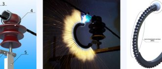
Power line voltage classes
The voltage class depends on the type of electrical network and it determines what voltage will be supplied through the power line to the consumer. Often, by the height of the line, the number and type of insulators, you can understand what voltage is transmitted along it. For example, 35 kV power lines have 3-5 insulators, and 110 kV - six to ten, etc. In residential buildings, the voltage is usually 220V, in production 380V. Classification is possible not only by voltage, but also by the type of current (alternating or direct), purpose (extra-long-distance, main, distribution), as well as by operating modes.
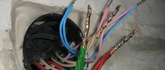
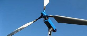
Installation of supports for VLZ-10kv
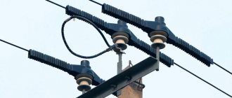
The SIP-3 wire can be mounted both on new supports and on existing ones, instead of bare AC-50-70-95-120 wires. Naturally, with the replacement of all load-bearing, fastening fittings and insulation. Replacing an old 10 kV overhead line with a new overhead line with SIP-3 wires is called reconstruction.
Both reconstruction and new construction must be carried out according to the project.
Most often, the installation of a new overhead line begins with the installation of anchor supports. Even before the anchor support post is raised, the required number of traverses are secured to it on the ground.
To prevent corrosion, and also because the line must be maintenance-free, it is necessary to use galvanized crossbars. Otherwise, in a few years you will have to re-climb each support and repaint the faded cross-arms to protect them from rust.
The traverse is immediately grounded. This is done by connecting a die clamp and a steel rod with a diameter of at least 10 mm (section 78.5 mm2) to the grounding outlet at the top of the support.
On reinforced concrete supports, both welded and bolted connections are allowed. On wood, it is recommended to use dies first.
On multi-post anchor supports, the number of grounding descents must be at least two. As such, you can use elements of longitudinal reinforcement of reinforced concrete racks SV-105-110.
All metal structures here (the strut fastening, the traverse itself) are grounded from above, through the grounding outlet. There is no need to make a separate descent made with a rod or strip, directly along the body of the support to the ground.
It is advisable not to screw the insulators onto the traverse onto the ground until the support is installed, in order to avoid accidental damage and damage during installation with special equipment. A partially equipped rack is installed at the desired point using a truck crane or a drill crane machine.
Then one or two struts are installed. Their number depends on the route layout and is determined by the project.
The support must be buried at least 2.3-2.5 meters. After this, intermediate supports are installed.
Sighting
For each span, at the project development stage, the sag boom is determined - the distance from the ground to the lowest point of the cable. This parameter is set based on the cross-section of the wire, its strength characteristics, as well as the climatic and weather conditions in which the power line will be operated. One of the most common methods of control is to take measurements using sighting rods mounted on support posts.
The design of the sighting strips, as well as the methods of their fastening, may be different.
Installation of power lines
If the installation of power lines
is carried out “under tension”, the following advantages are provided:
- heating of the cable caused by surface damage is eliminated;
- the occurrence of radio interference is excluded;
- the corona effect is absent or reduced;
- there is no need to interfere with the natural environment;
- the speed and efficiency of carrying out activities increases;
- work safety increases.
More photos here
“Installation of 160 kVA transformer substations in the Dmitrovsky district on a turnkey basis”
130 kW More details
“Power supply of an industrial zone. Execution of technical specifications of PJSC "MOESK" 130 kW"
130 kW More details
| IMPORTANT! In areas with populated areas and residential facilities, it is necessary to ground power lines to protect the lines from atmospheric surges. Grounding is equipped on supports that have branches to inputs to the facility (building, structure), as well as on the end poles of lines with branches. |
Laying fiber optic cables
In recent years, it has become necessary to lay fiber optic cable as an overhead cable line, with preference given to laying it over power lines. This approach has a number of advantages:
- coincidence of the directions of power lines with the directions of transmission of dispatch and technological information, including the use of free channels for commercial communications;
- no need to allocate land for the route;
- reducing the cost of construction and installation work;
- a significant reduction in construction time, since the construction of fiber-optic lines along power lines is simpler and more technologically advanced than underground installation;
- reduction in the number of mechanical damages compared to casings laid in the ground or sewerage;
- significant reduction in operating costs.
However, there are some limitations when installing overhead fiber optic cable lines. Thus, power lines are constantly under voltage and are often subject to the accumulation of static discharge, which causes interference in all cables. Installation of optical fiber must be carried out with the power line disconnected, to which not all owners give their consent. “It is necessary to obtain permission from the owners of overhead lines to carry out work, including disconnecting the voltage, which is regulated by the rules of work. In addition, the personnel must be trained and have permission to work on power lines and steeplejack operations,” experts note. In such a situation, additional laying along your own line, or an agreement on a parity basis, would be optimal.
When installing a fiber optic line, the latest technologies are used in the field of design surveys using precision remote tools. If necessary, our company uses, in particular, complex aerial topography, high-resolution photography, and laser location surveying. All this allows us to develop a concept for laying an overhead cable line for a fiber optic network, which implies the lowest consumption of materials with high efficiency; speed of installation and ease of maintenance; durability; intuitive cable routing, optimal suspension method.
How to determine the reliability of a cable? When the traction force is applied during the laying of overhead cable lines, the cable braid does not break, and the sheath does not burst at the fixed edges. To avoid further problems with low-quality products, only certified and tested cables, as well as power elements, are purchased. The resistance of optical self-supporting cables to tension is checked by our experts according to the existing E1 method for assessing the resistance of optical cables to tension (GOST R IEC794-1-93 “Optical cables. General technical requirements”) However, taking into account the fact that GOST is outdated, the requirements for laying air cable lines have been revised by us in the direction of significant tightening.
Our work is our responsibility
Over the years of work in the market for laying overhead cable lines, we have come to the conclusion that the experience we have accumulated and strict adherence to instructions for the safety and operation of various types of facilities have allowed us to guarantee the highest quality of work. Certified specialists, which are all our employees - from installers to engineers - are another guarantee that the laying of the line, be it power or communication, will be carried out perfectly. The client can observe this process, starting from the inspection of the work site, then at the design stage, and finally during installation, testing and commissioning.
Features of installation of overhead and cable power lines 10/0.4 k
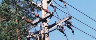
In most cases, electrical networks located in open areas are carried out by overhead lines.
In this case, specialists install intermediate supports on straight sections of the overhead line route. Corner supports are installed where the overhead line route changes its direction. Anchor supports must be installed at the intersections of electrical networks with any structures. End supports are installed at the beginning and end of the overhead line, and cross supports are installed in places where the line intersects in different directions.
As for cable lines, they are laid in such a way that the possibility of mechanical stress and damage is excluded. They are laid with a margin of 1%-2% to compensate for possible mail displacements, as well as temperature changes in both the cables themselves and the structures along which they were laid. In trenches and solid surfaces indoors, a supply of cable is made in a “snake” pattern, that is, laid in a wave-like manner. And if we talk about cable structures, then the reserve is left in the form of an arrow of sag. Under no circumstances is it permitted to create a reserve in the form of coils.
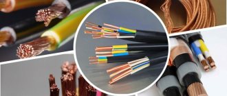
Technical characteristics of SIP-3 wire
Technical parameters and characteristics (cross-section, rated current, short-circuit current, diameter, weight) of high-voltage wire SIP-3:
More data - current, active, inductive reactance, voltage drop
The quality of the overhead line certainly depends on the quality of the wires used, but it equally also depends on the fittings used. When using proven materials, it is possible to build a maintenance-free overhead line with a service life of more than 40 years.
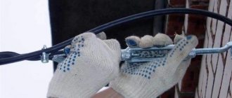
3.4. Wire connection in the span and on the support
3.4.1. If several drums with wire are used when rolling out the wire of one phase, the end of the wire of one drum is connected to the beginning of the wire of another drum. To do this, it is necessary to use special connecting clamps and the following devices and tools:
- sector scissors;
- peeling knife or rope;
— blowtorch or gas burner;
— a manual press with a set of matrices corresponding to the types of clamps.
3.4.2. Connecting clamps used on overhead line 6 - 20 kV can be pressed and automatic. The body of the compression clamp may be uninsulated or have an insulating coating. Non-insulated compression clamps, as well as automatic clamps, are usually supplied complete with a self-shrinking insulating sheath.
3.4.3. The following procedure for installing the press-on connection clamp is recommended:
— the ends of the wires are joined, the length of the section from which the protective sheath must be removed is determined and marked on them;
- the sheath is removed from these areas using a special knife for stripping insulation, rope or a mechanic's knife, while care must be taken to avoid damaging the metal core;
— bare sections of wires are coated with neutral lubricant and treated with a steel brush;
— one end of the wire is inserted into the clamp all the way and crimped, starting from the center to the edge of the clamp; the number of crimps, the number of the matrix are specified by the specification for the clamp;
— if the clamp does not have an insulating coating, then an insulating self-shrinking sheath is put on the second wire; then the end of the wire is inserted into the clamp all the way and crimped;
— the non-insulated parts of the wire and the clamp are covered with a self-shrinking sheath;
— the heat-shrinkable shell is heated with a blowtorch. Heating begins from the middle of the shell and the flame moves sideways from the center to the edges. The burner flame should be light and yellow (low temperature). The shell cools naturally;
— if the clamp has an insulating coating, then when connecting wires, crimping is performed directly on the insulating coating in accordance with the special recommendations specified in the specification for the clamp.
3.4.4. The following procedure for installing the automatic coupling clamp is recommended:
— the first three operations according to clause 3.4.3 are performed;
— one end of the wire is inserted into the automatic clamp until it stops and then jerked out in the opposite direction;
- a plastic insulating sheath is put on the end of the other wire; the wire is inserted into the clamp until it stops, then jerked out in the opposite direction;
— a plastic shell is put on the clamp and, if it is a heat-shrinkable shell, it is heated according to clause 3.4.3.
3.4.5. In loops of anchor-type supports, it is allowed to connect protected wires using die clamps in the same way as connecting bare wires.
Attention! There should be no tensile force in the die connection clamp.
Advantages of our company
Contacting our company provides customers with the following benefits:
- Transparent prices for services - we provide a detailed estimate for the construction of power lines, the customer can personally verify the accuracy of each figure and line of cost items;
- A detailed project that takes into account all the requirements of regulatory documents, conditions and wishes of the customer;
- Prompt execution of engineering surveys and approvals of working documentation;
- Carrying out all types of work on your own;
- Using materials and products from trustworthy manufacturers to implement the project;
- High quality of work, which we confirm with official guarantees.
3.3. Fastening wires on intermediate supports with pin insulators
3.3.1. To secure the protected wire to the insulators (having an upper groove) of the intermediate supports, as a rule, spring spiral ties with a polymer coating are used. The binding is applied over the protective sheath of the wire.
3.3.2. For reinforced fastening, a set of two spiral bindings is used. The wire is located in the insulator groove. The spiral should begin to be wound as close as possible to the insulator; each spiral is wound onto the wire on the opposite side of the insulator.
3.3.3. For intermediate fastening, either a single polymer-coated spring steel spiral tie or a plastic tie can be used.
3.3.4. When using pin insulators with a groove on a 6 - 20 kV overhead line (for example, type SDI 37 made in Finland), the wire laid in the groove is fastened with a set of two spiral ties. The first spiral covers the insulator and wire on one side, the second - the insulator and wire on the opposite side. This ensures enhanced fastening.
3.3.5. A diagram of the intermediate fastening of the wire to the neck of the insulator is shown in Fig. 26 [], using one spiral knitting.
3.3.6. Reinforced fastening of the wire to the neck of the insulator is ensured by applying a second spiral so that its turns occupy the free space between the turns of the first spiral.
3.3.7. Intermediate fastening of the protected wire to the head of the pin insulator is carried out using one spiral according to the diagram in Fig. 27 []; For this purpose, a spiral is used, shown in Fig. 28 [].
Advantages of cooperation with ENERGOGARANT
Power transmission lines are being installed in the Moscow region. We are ready to guarantee our clients quality services at an adequate cost. Our advantages 1. Professional workers Any mistake during installation can lead to large delays in work and large financial costs. To eliminate problems, our company has recruited only professionals to its team to guarantee quality. 2. Adequate cost Let's be honest, installing power lines is expensive. But even on this you can save your money if you contact. We do not add extra charges and guarantee an adequate price corresponding to the quality. 3. Availability of necessary equipment Our arsenal has everything necessary for installing power lines in the Moscow region. We take care of all the work, and you only have to wait a short time for the result. Any questions? Contact the specialists, and we will definitely answer them!