The length of 6-10-20 kV overhead lines made with SIP-3 wires is growing every year.
Such lines are called VLZ for short, which means overhead lines with protected wires. Do not confuse with VLI-0.4 kV - overhead lines with insulated wires, where SIP-1, SIP-2, SIP-4 are used for low voltage 220V-380V. It is the average voltage class of 6-10 kV that accounts for the main share of emergency shutdowns. Old 6-10 kV power lines made with bare wires are primarily susceptible to the influence of weather factors such as wind and ice. And the use of self-supporting wires with protective insulation can significantly improve their safety and reliability characteristics.
When using SIP-3, several parameters are reduced at once:
- interfacial distance
- width of cleared forest clearing
- space when arranging distribution units at a substation
All this is very beneficial from an economic point of view.
Technical characteristics of SIP-3 wire
Technical parameters and characteristics (cross-section, rated current, short-circuit current, diameter, weight) of high-voltage wire SIP-3:
More data - current, active, inductive reactance, voltage drop
The quality of the overhead line certainly depends on the quality of the wires used, but it equally also depends on the fittings used. When using proven materials, it is possible to build a maintenance-free overhead line with a service life of more than 40 years.
What brands of wires should I use?
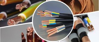
The brands of wires for power lines vary and depend on the voltage that will be transmitted through them. For example, for overhead power lines over 1000V, bare wires and cables that are resistant to atmospheric influences are used. Previously, copper wires were more often used, but now aluminum and steel are more popular. To understand the markings of wires, it is worth remembering that all grade A wires are made of aluminum or include it in their composition. M is copper grades of wires, B is bronze. A specialist should advise which brand of wire to choose, based on the many factors influencing the construction of power lines.
Installation of supports for VLZ-10kv
The SIP-3 wire can be mounted both on new supports and on existing ones, instead of bare AC-50-70-95-120 wires. Naturally, with the replacement of all load-bearing, fastening fittings and insulation. Replacing an old 10 kV overhead line with a new overhead line with SIP-3 wires is called reconstruction.
Both reconstruction and new construction must be carried out according to the project.
Most often, the installation of a new overhead line begins with the installation of anchor supports. Even before the anchor support post is raised, the required number of traverses are secured to it on the ground.
To prevent corrosion, and also because the line must be maintenance-free, it is necessary to use galvanized crossbars. Otherwise, in a few years you will have to re-climb each support and repaint the faded cross-arms to protect them from rust.
The traverse is immediately grounded. This is done by connecting a die clamp and a steel rod with a diameter of at least 10 mm (section 78.5 mm2) to the grounding outlet at the top of the support.
On reinforced concrete supports, both welded and bolted connections are allowed. On wood, it is recommended to use dies first.
On multi-post anchor supports, the number of grounding descents must be at least two. As such, you can use elements of longitudinal reinforcement of reinforced concrete racks SV-105-110.
All metal structures here (the strut fastening, the traverse itself) are grounded from above, through the grounding outlet. There is no need to make a separate descent made with a rod or strip, directly along the body of the support to the ground.
It is advisable not to screw the insulators onto the traverse onto the ground until the support is installed, in order to avoid accidental damage and damage during installation with special equipment. A partially equipped rack is installed at the desired point using a truck crane or a drill crane machine.
Then one or two struts are installed. Their number depends on the route layout and is determined by the project.
The support must be buried at least 2.3-2.5 meters. After this, intermediate supports are installed.
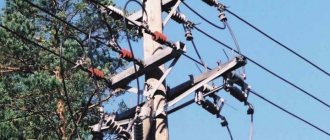
Air lines
Air lines are forming
according to an agreed project using:
- wires;
- traverse;
- fittings;
- supports;
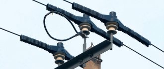
- insulators;
- arresters;
- lightning protection cables;
- sectioning devices;
- auxiliary equipment;
- grounding systems.
In the design of an overhead line, almost all aspects are important: selection of cable products, choice of installation location for supports and the route of the designed line, choice of type of supports, design type of poles, calculation of the length of sags, taking into account the preparation of the foundation for supports.
After the construction of the lines, it is necessary to connect the wires to the inputs in substations, switchgears, and buildings to the installed pantographs. We make sure to take these measures into account and carry out each stage.
More photos here
“Installation of a 160 kW transformer substation in New Moscow.”
149 kW More details
“Power supply for warehouse buildings. New technological connection to the networks of PJSC "MOESK"
200 kW More details
Installation of insulators at overhead lines
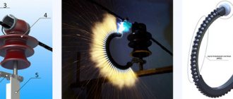
When all the supports are exposed, you can begin installing insulators on them. Moreover, here you can use both traditional porcelain insulators ШФ-20, and insulators of the new generation IF27 with a special plastic sleeve.
IF27 is more convenient to install and allows you to roll out SIP-3 wire without the presence of mounting rollers. Insulators are mounted on traverse pins or on support hooks using plastic caps KP-22.
However, it is not necessary to use modern brands of insulators everywhere. For example, on anchor supports for VLZ lines with SIP-3, the old time-tested glass insulators PS-70E, collected in garlands of at least 2 pieces, have proven themselves very well.
Technical characteristics of insulators from Ensto, Sicam, Niled for SIP-3:
EnstoSicamNiled
After installing the insulators, they begin to roll out the wires. The easiest way is to roll out and install directly along the grooves of the IF27 pin insulators.
If simple ShF-20 insulators are used, then you will need unrolling rollers, which must be installed on the cross-beams of the intermediate supports.
Rolling out SIP-3 wire
A power roller of a slightly different design with a bandage tape is attached to the initial anchor support. If the intermediate crossbars do not have loops or a hook from which the roller could be hung, then devices with bandage tape are used everywhere.
Technical characteristics and brands of mounting rollers from Ensto, Sicam, Niled, KVT:
EnstoSicamNiledKVT
Ensto
Sicam
Niled
KVT
In front of the very first support, a drum with SIP-3 wire is installed on a cable cart or on a cable jack.
Rolling out from the drum should be done in such a way as to prevent the wire from touching the ground and the support posts. A leader rope is used for this. It must be made of synthetic rope with a minimum diameter of 6mm.
A standard drum from Ensto ST204.2060-0030 easily fits 1100 m of such cable.
Basic requirements for the rope:
- high mechanical breaking load
- low susceptibility to stretching
- UV and moisture resistance
- dielectric
If the length of the cable is not sufficient, then it can be spliced together with special connecting brackets.
The ST204 motorized winch is secured to the final anchor support. A drum with a leader rope is placed on it.
The motor winch provides ease of installation and reduces the total operating time several times.
The portable sheeting machine is installed using a belt or chain banding device.
The leader cable is first pulled through the mounting roller on the final support, and then sequentially through the intermediate supports, pulling it along the grooves of the pin insulators.
It is possible to roll out SIP-3 directly onto insulators on intermediate supports if the angle of rotation of the route does not exceed 15 degrees.
The rope stretched across the entire anchor section is connected to the wire using a mounting stocking. The leader rope is simply tied with a compact knot directly to the loop of the mounting stocking. At the same time, unlike low voltage wires SIP-4, a swivel for SIP-3 does not need to be used.
The edge of the stocking is wrapped with turns of electrical tape to prevent it from slipping.
One of the installers uses the radio to give a command to the other, who controls the winch, to turn it on. He must also constantly monitor the passage of the cable-to-wire connection along the entire line. And if a wire gets stuck, immediately give the command to stop the winch.
The SIP wire must be pulled evenly, without jerking, at a speed of less than 5 km/h. When rolling out, do not allow the wire to touch the ground and support posts.
SIP wire tension
When SIP-3 has passed through the last power mounting roller on the end anchor support, the motorized winch is locked. The end of the wire is fixed in an anchor wedge clamp, for example DN Rpi or SO255.
Technical characteristics and brands of anchor clamps from Ensto, Sicam, Niled:
NiledSicamEnsto
The piercing clamp for the electrical connection of the cable loop with the wire is installed later, after the final tension of the line.
The technician on the support removes the wire from the mounting roller and disassembles the connection unit with the leader rope. Now you need to pull out and at the same time adjust the tension of the wire. This should be done with the obligatory use of a dynamometer in accordance with the installation tables. You can download it from here (from page 13).
The method of adjusting the tension of SIP without a dynamometer, guided only by the sag arrows, is not entirely correct.
The error in this case can reach significant values. Everything will depend not on the instruments, but on the eye of the particular installer. The human factor will play a significant role here, which is not at all correct.
The wire must be pulled using a hand winch from the cable drum side.
To do this, a little wire is wound from the drum, a frog mounting grip is attached to it, to which a dynamometer is in turn attached. And the hook of the hand winch clings to it.
The other hook of the winch is hooked to a reliable anchor on the ground. You can use a truck bumper as it.
The excess of wire tension should be no more than 5% of the value indicated in the installation table.
Next, the sag booms are aligned in all spans and compared with the calculated ones in the project.
After tensioning the SIP-3, the electrician on the support anchors the wire with a wedge clamp.
After which he immediately installs a branch piercing clamp with a cable to output the electrical potential of the wire to the clamp body. This is done to reduce the level of radio interference created by the overhead line and to prevent damage to the insulation of the self-supporting insulation system itself.
After this, you can cut the wire on the support in the right place, leaving the necessary margin and loop for further connection or connection with another SIP-3, or overhead line, cable line 6-10 kV.
Rolling and tensioning of the second and third wires is carried out in a similar way.
Carrying out dimensions measurements
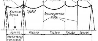
The most accurate, safe and effective way to determine distance is based on the use of optical instruments. This option allows you to obtain information without disconnecting the overhead power lines. A theodolite, altimeter or other products of similar purpose are suitable for the implementation of this task. The process is step-by-step; at the first stage, the height of the line suspension is assessed. On the second, measurements are taken to the lowest point of the wire sagging, as well as at intersections with roads or objects.
The sag of an overhead line wire is determined mathematically. The value varies depending on the outside temperature. If the power line is not put into operation, the assessment is carried out using a rod or rope with marks. Remember that incorrectly selected values cause accidents, “snaps” and breaks.
