| INTERSTATE COUNCIL FOR STANDARDIZATION, METROLOGY AND CERTIFICATION (MGS) INTERSTATE COUNCIL FOR STANDARDIZATION, METROLOGY AND CERTIFICATION (ISC) | |
| INTERSTATE | GOST 30324.2.9- |
| STANDARD | 2012 |
| (IEC 60601-2-9: 1996) | |
MEDICAL ELECTRICAL PRODUCTS
Part 2-9
Particular safety requirements for radiation therapy dosimeters electrically connected to radiation detectors in contact with the patient
(IEC 60601-2-9:1996, MOD)
Official publication
Moscow
Standardinform
2014
Content
Section one. General provisions………………………………….1
1 Scope and purpose…………………………………….1
2 Definitions………………………………………………………………. 2
5 Classification………………………………………………………2
6 Identification, marking and documentation……………………………..2
Section two. Environmental conditions…………………………….3
Section three. Protection against electrical hazards………………..3
15 Voltage and (or) energy limitation…………………………….3
Section four. Protection against mechanical hazards…………………………3
21 Mechanical strength……………………………………..3
Section five. Protection from the hazards of unwanted or excessive radiation………….4
Section six. Protection against the danger of ignition of flammable anesthetic mixtures…………4
Section seven. Protection from excessive temperatures and other hazards………………4
44 Overflow, splashing, leakage, moisture, liquid penetration, cleaning, sterilization
and disinfection………………………………………………………4
Section eight. Precise performance and protection from hazardous outputs
characteristics ……………………………………………………… 4
50 Performance Accuracy……………………………………4
Section nine. Abnormal operation and disturbance conditions; external influence tests
factors……………………………………………………5
Section ten. Design requirements……………………………..5
Appendix L (informative) Publications referred to in this standard……………6
Appendix AA (reference) Alphabetical index of terms…………………7
4 Materials
4.1 Introduction
The conductors must consist of one of the following materials: - annealed copper with or without metal coating; - made of aluminum or aluminum alloy.
4.2 Solid aluminum conductors
Single-wire round and shaped aluminum conductors must be made of aluminum that provides the tensile strength of the finished conductor within the limits specified in Table 1. Table 1 - Tensile strength of the finished conductor
| Nominal cross-section, mm | Tensile strength, N/mm |
| 10 and 16 | 110-165 |
| 25 and 35 | 60-130 |
| 50 | 60-110 |
| 70 or more | 60-90 |
| Note - The given values do not apply to aluminum alloy conductors. | |
4.3 Stranded aluminum conductors
Stranded round and shaped aluminum conductors must be made of aluminum that provides tensile strength of individual wires within the limits specified in Table 2. Table 2 - Tensile strength of individual wires
| Nominal cross-section, mm | Tensile strength, N/mm |
| 10 | Up to 200 incl. |
| 16 or more | 125-205 |
| Notes 1 The given values do not apply to aluminum alloy conductors. 2 The specified values are checked only on wires before twisting the core, but not on wires taken from the twisted core. | |
Introduction
This standard is a direct application of the international standard IEC 60601-2-9-96 “Medical electrical equipment. Part 2-9. Particular safety requirements for radiotherapy dosimeters electrically coupled to radiation detectors in contact with the patient" prepared by subcommittee 62 C "Apparatus for radiotherapy, dosimetry and nuclear medicine" of technical committee IEC 62 "Medical electrical devices".
The requirements of this standard amend, supplement or replace similar requirements of the general standard GOST 30324.0, take precedence over the requirements of the general standard and are mandatory. Following the requirements, this standard provides relevant test procedures.
To change the requirements of a general standard, the following words are used:
— the word “replacement” means that a clause of a general standard is replaced in its entirety by the text of this standard;
— the word “addition” means that the text of this standard is additional to the text of the general standard;
— the word “change” means that the text of a clause of a general standard is modified by the text of this standard.
This standard highlights:
- test methods - in italics;
- terms defined in paragraph 2 of the general and present standards, in GOST IEC 60601-1-1-2011, in publications IEC 60731 and IEC 60788, in capital letters.
The numbering of sections, clauses and subclauses of this standard corresponds to the numbering of sections, clauses and subclauses of the general standard. Sections, paragraphs, subparagraphs and figures that are introduced in addition to the general standard are numbered from 101. Additional annexes are designated by the letters AA, BB, and additional paragraphs by aa), cc).
DOSIMETERS intended for use in RADIOTHERAPY with RADIATION DETECTORS electrically coupled to the device may pose a hazard to the PATIENT if the RADIATION DETECTOR is intended to be used through physical contact with the PATIENT and the DOSIMETER is not designed to meet standards for protection against electrical hazards and mechanical hazards.
a) Most DOSIMETERS used in RADIOTHERAPY are not intended for physical contact with the PATIENT; they must meet the usual safety requirements for electronic measuring instruments set out in GOST 12.2.091.
c) If the DETECTOR UNIT in the DOSIMETER is intended for physical contact with the PATIENT during RADIOTHERAPY, then the more stringent requirements of this particular standard for electrical safety, durability and disinfection apply.
c) The design of the MEASURING SYSTEM complies with the requirements of GOST 30324.0 regarding permissible LEAKAGE CURRENTS TO THE PATIENT, since it is electrically connected to the RADIATION DETECTOR.
d) If the DETECTOR UNIT and the dosimeter MEASURING SYSTEM are supplied separately or can be separated, the user must be advised which connection of the detector unit and the measuring system meets the requirements of this particular standard for use through physical contact with the patient.
It is possible, for example, that a DETECTOR UNIT connected to an unsuitable MEASURING SYSTEM (even if each individually satisfies all requirements when connected to the relevant product) may inadvertently be switched on such that its ACCESSIBLE CONDUCTIVE PARTS are at high voltage; this combination may cause a safety hazard due to the high potential for high voltage grounding through the PATIENT's body and causing incorrect readings.
This particular standard specifies the requirements to be met by MANUFACTURERS regarding the design of DOSIMETERS intended for use in RADIOTHERAPY in direct contact with the PATIENT.
5 Single-wire and multi-wire conductors
The cores should not have burrs, cutting edges or bulging of individual wires.
5.1 Single-wire and multi-wire (for large cross-sections) conductors (class 1)
5.1.1 Design
a) For single-wire and multi-wire (for large cross-sections)
cores (class 1) use one of the materials listed in section 4.
b) Solid copper conductors must be round. For multi-core cables and wires, it is allowed to use shaped single-wire copper conductors with a cross-section of 25-50 mm .
Note - Solid copper conductors with a nominal cross-section of at least
70 mm
are intended for special types of cables, such as mineral insulated cables, but not for general purpose cables.
c) Single-wire conductors of aluminum and aluminum alloy with a nominal cross-section up to and including 35 mm must be round. Larger gauge conductors must be round for single-core cables and wires and may be round or shaped for multi-core cables and wires. For multi-core cables and wires, it is allowed to use shaped single-wire conductors made of aluminum and aluminum alloy with a cross-section of 25 and 35 mm .
5.1.2 Electrical resistance
The electrical resistance of the conductor at a temperature of 20 °C, determined in accordance with section 7, must be no more than the value specified in Table 3. Table 3 - Single-wire
and multi-wire (for large cross-sections)
class 1 conductors for single-core and multi-core cables
and wires
| Nominal cross-section, mm | Minimum number of core wires | Electrical resistance of 1 km of core at a temperature of 20 °C, Ohm, no more | |||
| Cu | A.I. | Round Annealed Copper Cores | Round or shaped conductors made of aluminum or aluminum alloy | ||
| without cover | with metal coating | ||||
| 0,03 | 1 | — | 588,0 | 617,3 | — |
| 0,05 | 1 | — | 347,9 | 365,3 | — |
| 0,08 | 1 | — | 225,3 | 238,8 | — |
| 0,12 | 1 | — | 130,8 | 138,6 | — |
| 0,20 | 1 | — | 88,8 | 90,4 | — |
| 0,35 | 1 | — | 50,7 | 51,8 | — |
| 0,50 | 1 | — | 36,0 | 36,7 | — |
| 0,75 | 1 | — | 24,5 | 24,8 | — |
| 1,0 | 1 | — | 18,1 | 18,2 | — |
| 1,5 | 1 | 1 | 12,1 | 12,2 | 18,1 |
| 2,5 | 1 | 1 | 7,41 | 7,56 | 12,1 |
| 4 | 1 | 1 | 4,61 | 4,70 | 7,41 |
| 6 | 1 | 1 | 3,08 | 3,11 | 5,11 |
| 10 | 1 | 1 | 1,83 | 1,84 | 3,08 |
| 16 | 1 | 1 | 1,15 | 1,16 | 1,91 |
| 25 | 1 | 1 | 0,727 | — | 1,20 |
| 35 | 1 | 1 | 0,524 | — | 0,868 |
| 50 | 1 | 1 | 0,387 | — | 0,641 |
| 70 | 1 | 1 | 0,268 | — | 0,443 |
| 95 | 1 | 1 | 0,193 | — | 0,320 |
| 120 | 1 | 1 | 0,153 | — | 0,253 |
| 150 | 1 | 1 | 0,124 | — | 0,206 |
| 185 | 1 or 35 | 1 | 0,101 | — | 0,164 |
| 240 | 1 or 35 | 1 | 0,0775 | — | 0,125 |
| 300 | 1 or 35 | 1 | 0,0620 | — | 0,100 |
| 400 | 1 or 35 | 1 or 35 | 0,0465 | — | 0,0778 |
| 500 | 35 | 1 or 35 | 0,0366 | — | 0,0605 |
| 625, 630 | 59 | 1 or 59 | 0,0283 | — | 0,0469 |
| 800 | 59 | 1 or 59 | 0,0221 | — | 0,0367 |
| 1000 | 59 | 1 or 59 | 0,0176 | — | 0,0291 |
| 1200 | — | 1 | — | — | 0,0247 |
| Aluminum conductors with a nominal cross-section up to 35 mm inclusive are round only; see item c) 5.1.1. See note to b) 5.1.1. See note to 5.1.2. For single-core cables, four sectored core pieces can be combined to form a round core. The maximum electrical resistance of the formed core must be equal to 25% of the value for each of the four sector parts of the core. | |||||
NOTE For solid aluminum alloy conductors having the same nominal cross-section as aluminum conductors, the electrical resistance value given in Table 3 shall be multiplied by a factor of 1.162 unless otherwise specified by agreement between the manufacturer and the purchaser.
5.2 Stranded round unsealed conductors (class 2)
5.2.1 Design
a) For stranded round unsealed conductors (class 2), use one of the materials listed in section 4.
b) The nominal cross-section of stranded aluminum or aluminum alloy power cables must be at least 10 mm.
c) All wires of each core must be of the same nominal diameter.
d) The number of wires of each core must be not less than the number of wires specified in Table 4. Table 4 - Class 2 stranded cores for single-core and multi-core cables and wires
| Nominal cross-section, mm | Minimum number of core wires | Electrical resistance of 1 km of core at a temperature of 20 °C, Ohm, no more | |||||||
| round | round compacted | shaped | Annealed copper core | Aluminum or aluminum alloy core | |||||
| Cu | A.I. | Cu | A.I. | Cu | A.I. | Uncoated wire | Metal Coated Wire | ||
| 0,5 | 7 | — | — | — | — | — | 36,0 | 36,7 | — |
| 0,75 | 7 | — | — | — | — | — | 24,5 | 24,8 | — |
| 1,0 | 7 | — | — | — | — | — | 18,1 | 18,2 | — |
| 1,5 | 7 | 7 | 6 | — | — | — | 12,1 | 12,2 | 22,7 |
| 2,5 | 7 | 7 | 6 | — | — | — | 7,41 | 7,56 | 12,4 |
| 4 | 7 | 7 | 6 | — | — | — | 4,61 | 4,70 | 7,41 |
| 6 | 7 | 7 | 6 | — | — | — | 3,08 | 3,11 | 5,11 |
| 10 | 7 | 7 | 6 | 6 | — | — | 1,83 | 1,84 | 3,08 |
| 16 | 7 | 7 | 6 | 6 | — | — | 1,15 | 1,16 | 1,91 |
| 25 | 7 | 7 | 6 | 6 | 6 | 6 | 0,727 | 0,734 | 1,20 |
| 35 | 7 | 7 | 6 | 6 | 6 | 6 | 0,524 | 0,529 | 0,868 |
| 50 | 19 | 19 | 6 | 6 | 6 | 6 | 0,387 | 0,391 | 0,641 |
| 70 | 19 | 19 | 12 | 12 | 12 | 12 | 0,268 | 0,270 | 0,443 |
| 95 | 19 | 19 | 15 | 15 | 15 | 15 | 0,193 | 0,195 | 0,320 |
| 120 | 37 | 37 | 18 | 15 | 18 | 15 | 0,153 | 0,154 | 0,253 |
| 150 | 37 | 37 | 18 | 15 | 18 | 15 | 0,124 | 0,126 | 0,206 |
| 185 | 37 | 37 | 30 | 30 | 30 | 30 | 0,0991 | 0,100 | 0,164 |
| 240 | 37 | 37 | 34 | 30 | 34 | 30 | 0,0754 | 0,0762 | 0,125 |
| 300 | 61 | 61 | 34 | 30 | 34 | 30 | 0,0601 | 0,0607 | 0,100 |
| 400 | 61 | 61 | 53 | 53 | 53 | 53 | 0,0470 | 0,0475 | 0,0778 |
| 500 | 61 | 61 | 53 | 53 | 53 | 53 | 0,0366 | 0,0369 | 0,0605 |
| 625 , 630 | 91 | 91 | 53 | 53 | 53 | 53 | 0,0283 | 0,0286 | 0,0469 |
| 800 | 91 | 91 | 53 | 53 | — | — | 0,0221 | 0,0224 | 0,0367 |
| 1000 | 91 | 91 | 53 | 53 | — | — | 0,0176 | 0,0177 | 0,0291 |
| 1200 | 0,0151 | 0,0151 | 0,0247 | ||||||
| 1400 | 0,0129 | 0,0129 | 0,0212 | ||||||
| 1600 | 0,0113 | 0,0113 | 0,0186 | ||||||
| 1800 | 0,0101 | 0,0101 | 0,0165 | ||||||
| 2000 | 0,0090 | 0,0090 | 0,0149 | ||||||
| 2500 | 0,0072 | 0,0072 | 0,0127 | ||||||
| These sections are not preferred. For special applications, other non-preferred conductor cross-sections are permitted but are not covered by this standard. The minimum number of wires for these sections is not standardized. The cores of these sections can be formed from four, five or six identical sectors. For stranded aluminum alloy conductors having the same nominal cross-section as aluminum conductors, the value of electrical resistance shall be agreed upon between the manufacturer and the purchaser unless specified in cable standards or specifications. | |||||||||
5.2.2 Electrical resistance
The electrical resistance of the core at a temperature of 20 °C, determined in accordance with section 7, must be no more than the value specified
in table 4
.
5.3 Stranded round cores and stranded shaped cores (class 2)
5.3.1 Design
a) For stranded round compacted conductors and stranded shaped conductors (class 2), use one of the materials given in section 4. The nominal cross-section of stranded round compacted conductors of aluminum or aluminum alloy shall be not less than 10 mm. The nominal cross-section of stranded shaped conductors made of copper, aluminum or aluminum alloy must be at least 25 mm.
b) The ratio between the diameters of two different wires of the same core should be no more than two.
c) The number of wires of each core must be at least the number of wires indicated in Table 4.
Note - This requirement applies to cores made from round wires before compaction and does not apply to cores twisted from pre-profiled wires.
d) In compacted conductors, wire breakage or skipping is allowed if the electrical resistance of the conductors meets the requirements of this standard.
5.3.2 Electrical resistance
The electrical resistance of the core at a temperature of 20 °C, determined in accordance with section 7, must not exceed the value specified
in table 4.
GOST 30324.2.9-2012 (IEC 60601-2-9:1996)
INTERSTATE STANDARD
MEDICAL ELECTRICAL PRODUCTS Part 2-9
Particular safety requirements for radiation therapy dosimeters electrically connected to radiation detectors in contact with the patient
Medical electrical equipment. Part 2-9. Particular requirements for the safety of patient contact dosemeters used in radiotherapy with electrically connected radiation detectors
Date of introduction - 2015—01—01
The clauses of the general standard apply, with the exception of:
6 Flexible cores (classes 3-6)
6.1 Construction
a) Flexible copper conductors (classes 3-6)
shall be of annealed copper with or without metal plating.
b) All wires of each core must be of the same nominal diameter.
c) The diameter of the core wires must not exceed the value specified in Tables 5-8.
d) Breakage or missing wires in the conductors is allowed if the electrical resistance of the conductors meets the requirements of this standard.
e) The conductors must not have burrs, cutting edges or bulging of individual wires.
6.2 Electrical resistance
The electrical resistance of the core at a temperature of 20 °C, determined in accordance with section 7, must be no more than the value specified
in tables 5-8. Table 5 - Class 3 stranded round conductors for single-core and stranded cables and wires
| Nominal cross-section, mm | Core wire diameter, mm, no more | Electrical resistance of 1 km of core at a temperature of 20 °C, Ohm, no more | ||
| Annealed copper core | Aluminum or aluminum alloy core | |||
| Uncoated wire | Metal Coated Wire | |||
| 0,50 | 0,33 | 39,6 | 40,7 | — |
| 0,75 | 0,38 | 25,5 | 26,0 | — |
| 1,0 | 0,43 | 21,8 | 22,3 | — |
| 1,5 | 0,53 | 14,0 | 14,3 | 23,4 |
| 2,5 | 0,69 | 7,49 | 7,63 | 12,5 |
| 4 | 0,87 | 4,79 | 4,88 | 8,00 |
| 6 | 0,65 | 3,11 | 3,17 | 5,20 |
| 10 | 0,82 | 1,99 | 2,03 | 3,33 |
| 16 | 0,65 | 1,21 | 1,24 | 2,02 |
| 25 | 0,82 | 0,809 | 0,824 | 1,35 |
| 35 | 0,69 | 0,551 | 0,562 | 0,921 |
| 50 | 0,69 | 0,394 | 0,402 | 0,658 |
| 70 | 0,69 | 0,277 | 0,283 | 0,470 |
| 95 | 0,82 | 0,203 | 0,207 | 0,338 |
| 120 | 0,79 | 0,158 | 0,161 | 0,264 |
| 150 | 0,87 | 0,130 | 0,132 | 0,211 |
| 185 | 0,87 | 0,105 | 0,107 | 0,175 |
| 240 | 0,87 | 0,0798 | 0,0814 | 0,134 |
| 300 | 0,87 | 0,0654 | 0,0666 | 0,109 |
| 400 | 0,87 | 0,0499 | 0,0509 | 0,0835 |
| 500 | 0,87 | 0,0393 | 0,0401 | 0,0657 |
| For stranded aluminum alloy conductors having the same nominal cross-section as aluminum conductors, the value of electrical resistance shall be agreed upon between the manufacturer and the purchaser unless specified in cable standards or specifications. | ||||
Table 6 - Class 4 Stranded Round Copper Conductors for Single and Stranded Cables, Wires and Cords
| Nominal cross-section, mm | Core wire diameter, mm, no more | Electrical resistance of 1 km of core at a temperature of 20 °C, Ohm, no more | |
| Uncoated wire | Metal Coated Wire | ||
| 0,05 | 0,11 | 366,6 | 383,7 |
| 0,08 | 0,13 | 247,5 | 254,6 |
| 0,12 | 0,16 | 165,3 | 170,3 |
| 0,20 | 0,21 | 89,1 | 91,7 |
| 0,35 | 0,27 | 57,0 | 58,7 |
| 0,50 | 0,31 | 40,5 | 41,7 |
| 0,75 | 0,31 | 25,2 | 25,9 |
| 1,0 | 0,31 | 19,8 | 20,4 |
| 1,5 | 0,41 | 13,2 | 13,6 |
| 2,5 | 0,43 | 8,05 | 8,20 |
| 4 | 0,53 | 4,89 | 4,99 |
| 6 | 0,53 | 3,28 | 3,35 |
| 10 | 0,53 | 2,00 | 2,04 |
| 16 | 0,53 | 1,21 | 1,24 |
| 25 | 0,53 | 0,776 | 0,792 |
| 35 | 0,59 | 0,547 | 0,558 |
| 50 | 0,59 | 0,393 | 0,401 |
| 70 | 0,59 | 0,281 | 0,286 |
| 95 | 0,59 | 0,201 | 0,205 |
| 120 | 0,69 | 0,162 | 0,165 |
| 150 | 0,69 | 0,129 | 0,132 |
| 185 | 0,69 | 0,104 | 0,106 |
| 240 | 0,69 | 0,0808 | 0,0824 |
| 300 | 0,69 | 0,0649 | 0,0661 |
| 400 | 0,69 | 0,0484 | 0,0493 |
Table 7 - Class 5 Flexible Round Copper Conductors for Single and Stranded Cables, Wires and Cords
| Nominal cross-section, mm | Core wire diameter, mm, no more | Electrical resistance of 1 km of core at a temperature of 20 °C, Ohm, no more | |
| Uncoated wire | Metal Coated Wire | ||
| 0,03 | 0,09 | 572,7 | 599,5 |
| 0,05 | 0,09 | 400,9 | 419,6 |
| 0,08 | 0,11 | 256,6 | 268,6 |
| 0,12 | 0,11 | 171,0 | 179,0 |
| 0,20 | 0,13 | 108,3 | 113,4 |
| 0,35 | 0,16 | 58,3 | 60,0 |
| 0,50 | 0,21 | 39,0 | 40,1 |
| 0,75 | 0,21 | 26,0 | 26,7 |
| 1,0 | 0,21 | 19,5 | 20,0 |
| 1,5 | 0,26 | 13,3 | 13,7 |
| 2,5 | 0,26 | 7,98 | 8,21 |
| 4 | 0,31 | 4,95 | 5,09 |
| 6 | 0,31 | 3,30 | 3,39 |
| 10 | 0,41 | 1,91 | 1,95 |
| 16 | 0,41 | 1,21 | 1,24 |
| 25 | 0,41 | 0,780 | 0,795 |
| 35 | 0,41 | 0,554 | 0,565 |
| 50 | 0,41 | 0,386 | 0,393 |
| 70 | 0,51 | 0,272 | 0,277 |
| 95 | 0,51 | 0,206 | 0,210 |
| 120 | 0,51 | 0,161 | 0,164 |
| 150 | 0,51 | 0,129 | 0,132 |
| 185 | 0,51 | 0,106 | 0,108 |
| 240 | 0,51 | 0,0801 | 0,0817 |
| 300 | 0,51 | 0,0641 | 0,0654 |
| 400 | 0,51 | 0,0486 | 0,0495 |
| 500 | 0,61 | 0,0384 | 0,0391 |
| 625 , 630 | 0,61 | 0,0287 | 0,0292 |
Table 8 - Class 6 Flexible Round Copper Conductors for Single and Stranded Cables, Wires and Cords
| Nominal cross-section, mm | Core wire diameter, mm, no more | Electrical resistance of 1 km of core at a temperature of 20 °C, Ohm, no more | |
| Uncoated wire | Metal Coated Wire | ||
| 0,03 | 0,06 | 669,8 | 671,5 |
| 0,05 | 0,06 | 396,9 | 397,9 |
| 0,08 | 0,06 | 267,9 | 268,6 |
| 0,12 | 0,09 | 174,4 | 174,8 |
| 0,20 | 0,11 | 113,1 | 113,4 |
| 0,35 | 0,11 | 59,5 | 59,6 |
| 0,50 | 0,16 | 39,0 | 40,1 |
| 0,75 | 0,16 | 26,0 | 26,7 |
| 1,0 | 0,16 | 19,5 | 20,0 |
| 1,5 | 0,16 | 13,3 | 13,7 |
| 2,5 | 0,16 | 7,98 | 8,21 |
| 4 | 0,16 | 4,95 | 5,09 |
| 6 | 0,21 | 3,30 | 3,39 |
| 10 | 0,21 | 1,91 | 1,95 |
| 16 | 0,21 | 1,21 | 1,24 |
| 25 | 0,21 | 0,780 | 0,795 |
| 35 | 0,21 | 0,554 | 0,565 |
| 50 | 0,31 | 0,386 | 0,393 |
| 70 | 0,31 | 0,272 | 0,277 |
| 95 | 0,31 | 0,206 | 0,210 |
| 120 | 0,31 | 0,161 | 0,164 |
| 150 | 0,31 | 0,129 | 0,132 |
| 185 | 0,41 | 0,106 | 0,108 |
| 240 | 0,41 | 0,0801 | 0,0817 |
| 300 | 0,41 | 0,0641 | 0,0654 |
The electrical resistance of multicore cable products with conductors of classes 4-6, twisted with a multiplicity of steps of less than 10 twist diameters, must be specified in the standards or technical specifications for cable products.
Why is the calculation made?
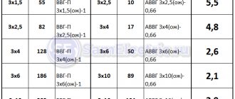
Among the reasons why tables for selecting cross-sections in cables by power are used are the following:
- Compliance with safety rules.
- Compliance with the wiring conditions.
- Providing residential premises with a stable flow of electrical energy.
- Avoiding unnecessary investments.
- Formation of knowledge about wiring in your home or apartment.
If you are completely confident in fulfilling all these factors, then you will be able to avoid unexpected breakdowns and subsequent repairs. Even if incorrectly selected indicators of wire cross-sections for currents and power only lead to a communications malfunction, then in order to restore the devices’ access to operation, you will encounter the following problems:
- Removing plaster or wallpaper from the places where the wiring lies;
- Purchasing new cables and replacing old ones;
- In case of breakdown of electrical appliances, replace or repair them.
From this we conclude that it is better to spend a little time at the very beginning than to burden yourself with unnecessary worries later.
Video
Handle-bracket, BRANTE, set of 4 pieces RS.1424 96.BK
340 ₽ More details
PVC balcony handle AC RemOkno (plastic)
144 ₽ More details
Men socks
What will mistakes lead to?
If you do not use 220V copper cable cross-section plates, an incorrect calculation will lead to the following consequences:
- Wiring overheating. As a result, it will fail, as well as a fire. If no one is home at this moment, the consequences may be more serious;
- Invest in new cables. In order to install safe cables later, you will need to purchase entire uteruses of new samples.
Avoiding such consequences is the main reason for using a 220 power wire size chart.
Appendix A (mandatory). Electrical resistance measurement
Appendix A (mandatory)
The cable product is kept in the test room for a sufficiently long time so that the core reaches a temperature at which the electrical resistance can be accurately determined using specified correction factors. The direct current electrical resistance of the core(s) is measured either on the construction length of the cable product, or on a sample of the cable product with a length of at least 1 m at ambient temperature, and the temperature at which the measurement was taken is recorded. The measured electrical resistance is corrected using the correction factors given in Table A.1. Table A.1 — Temperature correction coefficient for bringing electrical resistance measured at °C to 20 °C
| Core temperature when measured °C | Correction temperature coefficient for all core classes |
| 0 | 1,087 |
| 1 | 1,082 |
| 2 | 1,078 |
| 3 | 1,073 |
| 4 | 1,068 |
| 5 | 1,064 |
| 6 | 1,059 |
| 7 | 1,055 |
| 8 | 1,050 |
| 9 | 1,046 |
| 10 | 1,042 |
| 11 | 1,037 |
| 12 | 1,033 |
| 13 | 1,029 |
| 14 | 1,025 |
| 15 | 1,020 |
| 16 | 1,016 |
| 17 | 1,012 |
| 18 | 1,008 |
| 19 | 1,004 |
| 20 | 1,000 |
| 21 | 0,996 |
| 22 | 0,992 |
| 23 | 0,988 |
| 24 | 0,984 |
| 25 | 0,980 |
| 26 | 0,977 |
| 27 | 0,973 |
| 28 | 0,969 |
| 29 | 0,965 |
| 30 | 0,962 |
| 31 | 0,958 |
| 32 | 0,954 |
| 33 | 0,951 |
| 34 | 0,947 |
| 35 | 0,943 |
| 36 | 0,940 |
| 37 | 0,936 |
| 38 | 0,933 |
| 39 | 0,929 |
| 40 | 0,926 |
| NOTE The temperature correction coefficient values are based on a resistance temperature coefficient of 0.004 K at 20 °C. The temperature correction coefficient values given in Table A.1 are approximate, but they provide values for practical use that are consistent with the reliability that can typically be obtained from temperature and length measurements of cable products. A method for obtaining more accurate temperature correction coefficient values for copper and aluminum is given in Annex B. But these values should not be taken as a requirement for tests carried out in accordance with this standard to verify electrical resistance. | |
Electrical resistance per 1 km of cable product length is calculated based on the length of the finished cable product, and not the length of individual insulated cores or wires. If necessary, the adjustment to be made to bring the electrical resistance value to 20 °C and a length of 1 km can be made using the following formula
, (A.1)
where is the electrical resistance of 1 km of core at 20 °C, Ohm; — measured electrical resistance of the core, Ohm; — correction temperature coefficient specified in Table A.1; — length of the cable product, m.
Shorted or broken conductors in a cable or wire
To determine whether there is a short circuit between the wires in the cable or to verify the integrity of the wire, you need to take a tester, multimeter or indicator screwdriver. It is necessary to “ring” the cable wires so that they do not ring each other, for example, the blue wire at one end and the white wire at the other. But at the same time, same-color (of the same name) conductors from different ends of the conductor must be called.
But the case of broken or shorted wires is a case of defects, and now let’s move on to issues that relate to the manufacturer’s desire to save more and reduce the cost of the cable as much as possible, and, as a result, make it cheaper.
Common cross-sections for wiring in an apartment
If you hire the services of an electrician, he will use a table of the cross-section of copper wires by power to make a decision. However, there are standard values that are most often used in apartments:
- Lighting:
- Appliance sockets:
If there are a certain number of boilers, induction cookers and other installations that require large energy reserves, an individual calculation is carried out.
Current loads in DC networks
For DC consumers, it is important that the voltage at the ends is not lower than 0.5 V.
There is a formula that determines how much the voltage at the ends will drop compared to the base voltage, depending on the length of the conductor, its specific resistance and current strength in c epi:
U = ((pl) / S) I where:
- U — direct current voltage, V;
- p — specific resistance of the wire, Ohm*mm2/m;
- l — wire length, m;
- S—cross-sectional area, mm2;
- I - current strength, A.
Knowing all the values, you can calculate the wiring cross-section. This rule also works for circuit breakers for networks.
The cable that transmits electric current is an important element of the entire system. Calculating its performance and power gives confidence in the security of the entire network and the devices connected to it.
What is needed for load calculations
The main indicator that helps to calculate the cross-section and brand of cable is the maximum permissible long-term load.
A simple arithmetic summation of the powers of all electrical appliances that will be connected to the network is necessary.
Having received the exact value of the current, you should refer to the tables that allow you to find a cable or wire of the required cross-section and material.
Calculation for premises
The total load in the room consists of power and lighting. Remember that the kitchen and bathroom are the most loaded lines, so you should be especially careful when choosing cables in these two locations.
And distribute the load across different socket groups, rather than using a pilot for 5-6 sockets.
Keep in mind that consumption and power should be calculated individually and using cable power tables for each room in the apartment.
Closed or open wiring
The load also depends on the type of wiring: closed or open.
For example, if the house is made of brick or concrete, the wiring should be covered with plaster, and if it is wooden, then the wiring should run along a special treated surface.
Thus, calculating the cross-section of wires is an important process. It will take little time, but you will be confident in the correctness and safety of the wires you have selected.