Many different laboratory power supplies are presented on the Internet on radio engineering sites, although mostly simple designs. This same circuit is characterized by a fairly high complexity, which is justified by the quality, reliability and versatility of the power supply. We present a completely homemade power supply with bipolar 2 x 30 V, with adjustable current up to 5 A and a digital LED A/V meter.
In fact, these are two identical power supplies in one case, which significantly increases the functionality and capabilities of the device, allowing you to combine channel powers up to 10 Amps. At the same time, this is not a typical symmetrical power supply, although it can be connected in series outputs to achieve higher voltage or pseudo-symmetry, treating the common connection as ground.
Diagrams of laboratory power supply modules
All power board circuits were designed from scratch, and all printed circuit boards are also independently developed. The first module “Z” is a diode bridge, voltage filtering, negative voltage generation to power the op amps, a 34 VDC positive voltage source for the op amps, powered by a separate auxiliary transformer, a relay used to switch the main transformer windings controlled from another circuit board, and a 5V 1A power supply for power meters.
The “Z” modules of both units were designed to be almost symmetrical (to fit better into the PSU case). Thanks to this, the ARK connectors were placed on one side to connect the wires and heatsink for the bridge rectifier, and the boards, as shown in the pictures, were placed symmetrically.
An 8-amp diode bridge is used here. The main transformers have dual secondary windings, each 14 V and a current of just over 5 A. The power supply was rated for 5 amps, but it turned out that at full voltage 30 V does not produce the full 5 A. However, there is no problem with a 5 amp load at lower voltage (up to 25 V).
The second module is an expanded version of the power supply with operational amplifiers.
Depending on whether the power supply is loaded or in standby mode, the voltage in the region of the amplifier U3, responsible for limiting the current, changes (with the same setting of the potentiometer limits). The circuit compares the voltage across potentiometer P2 with the voltage across resistor R7. Part of this voltage drop is applied to the inverse input of U4. Thanks to this, the output voltage depends on the potentiometer setting and is practically independent of the load. Almost because on a scale from 0 to 5 A the deviation is at the level of 15 mV, which in practice is enough to obtain a stable source for driving the LM3914 circuits that form the LED bar.
The visualization diagram is especially useful when multi-turn potentiometers are used for adjustment. It’s great that with the help of such a potentiometer you can easily set the voltage accurate to the third decimal place. Each LED in the line corresponds to a current of 0.25 A, so if the current limit is below 250 mA, the line is not displayed. The ruler display method can be changed from dot to ruler, but dot is selected here to avoid the influence of too many light dots and reduce power consumption.
The next module is the winding switching system and fan control system that are installed on the radiators of old processors.
The circuits are powered by independent windings of an auxiliary transformer. Here we use m/s op-amp LM358, which contains two operational amplifiers inside. A BD135 transistor is used as a temperature sensor. After exceeding 55C, the fans turn on, and after cooling to approximately 50C, they automatically turn off. The winding switching system reacts to the voltage value at the direct output terminals of the power supply and has a hysteresis of about 3 V, so the relay will not operate too often.
Measurement of load voltage and current is carried out using ICL7107 chips. The meter boards are double-sided and are designed such that for each power source there is a voltmeter and an ammeter on one board.
Useful: DIY LED tail lights for cars
From the very beginning, the idea was to visualize power supply parameters on seven-segment LED displays because they are more readable than an LCD display. But nothing prevents you from measuring the temperature of radiators, winding switches and cooling systems on one Atmega MK, even for both power supplies at once. It's a matter of choice. Using a microcontroller will be cheaper, but as mentioned above, this is a matter of taste.
All auxiliary systems are powered by a transformer that has been rewound by removing all windings except the 220V mains (primary). TS90/11 was used for this purpose.
The secondary winding is wound with 2 x 26 V AC to power the operational amplifiers, 2 x 8 V AC to power the indicators and 2 x 13 V to power the temperature control. A total of six independent windings were created.
A regulated power supply is a must-have attribute on a radio amateur's desk, but due to their considerable cost, many prefer to make a laboratory power supply with their own hands. Power supplies are linear and switching; the main advantage of switching circuits is their high efficiency (>90%). Linear circuits have low efficiency, but provide cleaner output voltages, which are characteristic of switching power supplies.
Linear power supplies are better, but when designing such high-power power supplies, problems arise with cooling the power transistors.
What is the main difficulty? Let's say we have assembled a power supply with voltage regulation from zero to 30 Volts and current from zero to 5 Amps. And if we set the output to a low voltage and a high current, for example 3 Volts and 5 Amps, the output power will be about 9 Watts, while the transistor will have a voltage drop of at least 27 Volts, taking into account a current of 5 Amps, we will get about 140 watts power in the form of useless heat that needs to be removed.
There are two main options for solving this problem:
- A huge radiator with a fan to cool the power transistor;
- Transformer winding switching system.
The second option is the most preferable, and will allow you to get rid of massive radiators and a noisy fan.
The principle of operation is very simple - at low output voltages, a low voltage is also supplied to the input. Thus, the power dissipated by the transistor will be much less, the efficiency increases significantly.
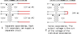
But in order to use the switch, you need to have a transformer with several secondary windings, preferably with completely identical parameters, for example, three windings of 12 Volts each.
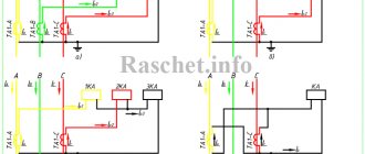
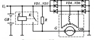
Before you now is the simplest and most trouble-free relay switch circuit.
We have a pair of zener diodes for the same voltage and a pair of relays controlled by low-power reverse conduction transistors. Point “A” is connected to the output of the laboratory power supply. Total food mass. The switch circuit is powered by a separate, low-power winding.
The circuit works as follows: if the voltage at the output of the laboratory power supply unit is below 12 Volts, the zener diode is closed. If the voltage at the output of the laboratory power supply is more than 12 Volts, the first zener diode instantly opens, the signal goes to the base of the first transistor, unlocking it, and through the open transition, power is supplied to the relay winding, as a result, the relay will also work, switching the corresponding winding. Now a voltage of 24 Volts is supplied to the input of the stabilizer.
When the output voltage of the power supply increases to a threshold value, and this is the sum of the voltages of both zener diodes, the second zener diode will open in exactly the same way, which will lead to the unlocking of the second transistor and the second relay will operate, and the input of the stabilizer will receive the full voltage from all three series-connected windings of the transformer .
At this moment, the first relay is also in the on state, but since power is supplied through the second relay, this does not affect the output voltage. By adding another transistor with a zener diode to the circuit, you can turn it off at these moments.
If the voltage at the output of the power source is greater than the sum of the stabilization voltages of the zener diodes, the third transistor will open, bypassing the base of the transistor that controls the first relay to the power ground, it will close and turn off the relay.
It is worth noting that negligible currents flow through the zener diodes and base-emitter junctions.
The circuit uses relays with a coil voltage of 12 Volts.
Diodes are designed to protect against breakdown of control transistors by self-induction voltage from the relay windings during their shutdown.
The relay switching current depends on your power supply; if you are designing a 5 Ampere laboratory power supply, it is advisable to take the relay with a double reserve, for example 10-12 Amperes.
Basic limiting resistors for transistors can range from 6.8 to 15 kOhms. The transistors themselves are reverse conduction, you can take any low and medium power.
The disadvantages of the circuit include the use of an electromagnetic relay. I must say that many industrial power supplies use exactly this solution. Relays make a sound when switching, and the contacts do not last forever.
There are systems where the switching element is a triac, but such switches are also not ideal, problems with control often arise, and there will be losses on the triacs themselves, hence heating, and besides, triac circuits are quite complex.
The switching circuit can be powered either from a separate winding, which is wound on the main transformer, or from a separate low-power power supply. The voltage of this source should be from 18 to 20 volts, with a current of 200-300mA.
PCB here
Housing and assembly costs
The entire power supply is housed in a housing that was also designed from scratch. It was made to order. It is known that it is difficult to make a decent box (especially a metal one) at home.
The aluminum bezel used to mount all indicators and accessories was milled to fit the design.
Of course, this is not a low-budget implementation, given the purchase of two powerful toroidal transformers and the custom-made housing. If you want something simpler and cheaper, make such power supplies.
The rest can be estimated based on prices in online stores. Of course, some elements were obtained from our own stock, but these too will need to be purchased, creating a power supply from scratch. The total cost was 10,000 rubles.
Assembly and configuration of LBP
We recommend building this laboratory power supply in the following order:
- Assembling and testing a module with a bridge rectifier, filtering and relay, connecting to a transformer and activating a relay from an independent source to check the output voltages.
- Execution of the module for switching windings and monitoring radiator cooling. Running this module will make it easier to configure the future power supply. To do this, you will need another power source to supply a regulated voltage to the input of the system responsible for controlling the relay.
- The temperature portion of the circuit can be tuned by simulating the temperature. For this purpose, a heat gun was used, which gently heated a radiator with a sensor (BD135). Temperature was measured using a sensor included in a multimeter (at that time there were no ready-made accurate temperature meters). In both cases, the setup comes down to selecting PR201 and PR202 or PR301 and PR302, respectively.
- We then run the power supply by adjusting RV1 to produce a 0V output, which is useful for setting current limiting. The limitation itself depends on the values of resistors R18, R7, R17.
- Regulation of A/V indicators comes down to adjusting the reference voltages between pins 35 and 36 of the ICL microcircuits. Voltage and current meters used an external reference source. In the case of temperature meters, such precision is not needed, and the display with a decimal point is still somewhat exaggerated. Temperature readings are transmitted by one rectifier diode (there are three in the diagram). This is due to the PCB design. There are two jumpers on it.
- Directly at the output terminals, a voltage divider and a 0.01 Ohm / 5 W resistor are connected to the voltmeter, across which the voltage drop is used to measure the load current.
An additional element of the power supplies is a circuit that allows only one power supply to be turned on without the need for a second channel, despite the fact that the auxiliary transformer powers both channels of the power supply at once. On the same board there is a system for turning the power supply on and off using one low-current button (for each channel of the power supply).
The circuit is powered by an inverter, which in standby mode consumes about 1 mA from a 220 V network. All circuits can be found in good quality
Laboratory power supply board, my design and additions. Multi-review.
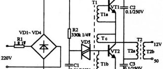
This text was written not so much for the sake of reviewing the power supply board itself, respected Kirich and other authors succeeded in this, but rather for the sake of describing the design I received as a whole, with the additions necessary, in my opinion, for this power supply in the form of a fan thermal controller and indicator voltage and current, automatic switch of transformer windings, electronic load disconnection, and the power transformer itself and the housing. Some of the devices were purchased on AliExpress, and the other part was assembled from scratch. For the former there will be links, and for the latter there will be diagrams... So, the components used: - A ready-made 150W toroidal transformer, having 2 windings of 12 volts each, purchased in a chip and a dip. Such a transformer was chosen taking into account the possibility of switching windings, dividing the range of output voltages into 2 subranges - 0-11V and everything higher (using either one 12 volt winding or 2 series-connected windings of the same type, giving a total of ~24V). On top of the two factory secondary windings, 2 additional windings were wound. The first is a low-power 13V to power additional devices and a cooling fan. The second winding is more powerful, 7V, wound with a 1.5mm wire (I could have used a thinner one, but I had one), to power a separate 5V USB output connected to a 7805 linear stabilizer;
— Design board for laboratory power supply from AliExpress. The set really began to cost a penny - a little more than $5. Flew to Minsk in 29 days, the track was tracked. The board I assembled is pictured above. I only replaced the complete 10,000 µF condenser and the rectifier diodes with Schottky diodes SR560 for a current of 5A. Change operational amplifiers before you start...;
— Ready-made fan controller board with temperature indicator and remote temperature sensor, also from AliExpress.
The temperature controller, costing $1.65, arrived in Minsk in 22 days, the track was tracked. An excellent device, I must say. It can operate in one of two modes - cooling or heating. That is, depending on the selected mode, the thermal controller controls either the heater (turns on if the temperature drops below the set one) or the fan (turns on if the temperature exceeds the set one). To turn off the fan or heater, set the hysterisis value. The controller is controlled using 3 buttons, the values are displayed on a 3-character indicator. There are detailed instructions on the seller's page Instructions
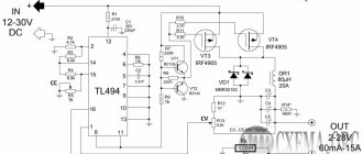
; — Ready-made voltage and current indicator from AliExpress. Price $3.94. The order took 5 weeks to arrive, the track was not tracked. It should be noted that the indicator turned out to be quite suitable, we will test it later;
— A homemade unit for switching transformer windings (the circuit was found on the Internet). This is perhaps the most important addition to a linear regulated power supply. The fact is that the efficiency of such sources is not very high, especially at low output voltages. So, for example, with an output voltage of 5V and a current of, say, 3A, the output transistor should dissipate about 75W. And in this mode, when the power supply is powered by 24 volts AC (2 windings of 12 volts), the cooling fan, controlled by a thermal controller, almost never turns off. And with an input voltage of ~12V, on the contrary, it turns on very rarely and for a short time. Thus, this addition allows you to significantly improve the operating modes of the power supply, especially considering that I mainly use voltages up to 12V. The only thing is that the solution I have chosen is not the best, because when the voltage decreases, at the moment of switching the windings from two to one (from 24V to 12V), a short dip in the output voltage occurs. The triac circuit is devoid of such a drawback. But for myself, I decided that this nuance is not important to me. The device is assembled on a breadboard; a rectifier and a 12V voltage stabilizer are located right there, from which the relay, thermal controller and fan are powered. For this stabilizer, an additional low-power winding was wound on the transformer;
— And this is a completely homemade electronic load connection unit, more about it: So, a small technical specification.
— After turning on the power supply, the load must be disconnected, regardless of the last state. — The switched off load should be indicated by a flashing red LED. — A constantly lit green LED should indicate that the load is on. — The load is connected using a relay. — Hardware contact bounce suppression.
The circuit has been corrected, thanks to users IIIap, varicap and alexky who noticed it (wrong polarity of the protective diode). The circuit is built on a cheap Atmel ATtiny2313 microcontroller and a 74HC14 Schmitt trigger. The circuit is powered by 12 volts, which are necessary for the relay to operate. A 7805 linear converter is used to power the microcircuits.
After switching on, the red LED VD2 flashes. The 74HC11 Schmitt trigger allows you to finally and irrevocably get rid of contact bounce. When the button is pressed, LED VD2 goes out and VD1 (green) lights up, at the same time transistor VT1 opens and relay K1 turns on. The next time you press the load and the green LED VD1 are turned off, the red LED VD2 starts flashing. Diode VD1 protects the transistor from voltage surges on the relay coil. The circuit is assembled on a breadboard. If you do not install a Schmitt trigger at the input (and deal with bounce using software), then you need a 10K pull-up resistor on pin 7 of the microcontroller. There are plans to add another control channel to the int0 microcontroller input. The USB output will be controlled.
The control program is written in the Bascom environment.
In the main cycle, the red LED flashes, provided that the PB2 output is low, i.e. the load is disconnected and the green LED is off. When Int1 is interrupted, the Swbutton subroutine is called. The Toggle operator switches the states of the PB2 output (if it was 1, it will become 0 and vice versa). After switching the output, the program returns to the main loop until the next interruption;
The source is under the spoiler
$regfile = "attiny2313.dat" $crystal = 4000000 Config Portb.1 = Output Config Portb.2 = Output Config Pind.3 = INPUT Config Int1 = Falling
Dim Time As Byte
On Int1 Swbutton
Cls
Wtime = 255
Enable Interrupts Enable Int1
Do if pinb.2 = 0 Then Set Portb.1 Waitms Wtime Reset Portb.1 Waitms Wtime Else 'Pinb.4 = 0 End If Loop End
Swbutton: Toggle Portb.2
Return
End
— Relay. On the left is a relay in a blue case, used to turn on/off the load, and a relay in a transparent case, the first group of contacts switches the transformer windings, and the second group turns on the LED indicating the connection of the second winding;
— And finally, the finished case from the old tape streamer. 2Gb DDS cartridges have not been relevant for a very long time, so the device was mercilessly disassembled for spare parts. And the case with its original fan was perfect for my power supply;
This is the front panel. Temporary, because I will redo the layout and the material of the insert will need to be changed (it was white foam plastic - it looks clumsy, but there will be a plug from the computer case, which matches the color of the entire device). But this will happen a little later, when multi-turn resistors arrive from China. A USB connector will also be added. The red regulator is voltage, the blue one is current (the colors of the knobs are selected in accordance with the colors of the indicator segments). The rectangular green LED under the indicator begins to glow when the second winding of the transformer is connected. Above the blue regulator is an LED indicating current stabilization (red). Well, in the area of the output terminals there is a red load connection button and a two-color LED (red-green).
Everything is done on connectors - the front panel is completely removable. The output of the power supply is connected to the front panel via a Deans type connector, which is used for batteries of remotely controlled models;
All components are connected to each other according to the following diagram (corrected, thanks to user MisHel64):
A little assembly:
The winding switch and load disconnect blocks are assembled into a sandwich and installed near the front panel. A load disconnect relay and a fan thermal controller board are installed nearby.
On the inside, a radiator (from some old processor) is screwed to the case fan. A transistor and a thermal controller sensor are screwed to the radiator using thermal paste. Everything is installed in the case from the back.
The main board is mounted on high racks with the parts facing down. Although this arrangement is not the most thermally efficient, there is no other way to place the board and transformer in this case.
I decided to connect the transformer windings using Wago terminals, it turned out very convenient. The wires are a little messy, although they were laid out and tied together with zip ties. Maybe I’ll redo it later... And the last component is a 5V stabilizer, mounted on a radiator. And a couple of final photos, a rear view and the assembled power supply. On the back are the power connector, power switch, fuse and switch (blue) for the additional 5V line.
Now let's move on to testing. Let me make a reservation right away that we will be testing not so much the power supply board itself, but the entire assembly assembly. Let's start with the indicator. Under the spoiler there are visual photos of testing. The readings were compared with the reference professional digital multimeter Aktak AM-1095.
Voltmeter reading testing
The ammeter was tested using a 10 Ohm 50 W load resistor.
If we remember Ohm's law, we can easily estimate that with this resistor, the current readings should be 10 times less than the voltmeter readings, which we will now verify. We will continue to compare the readings with Aktacom.
Testing ammeter readings
After the measurements, I even began to respect this indicator and I wanted to call it a “device”)).
But it was not possible to get more than 26V from the power supply board at a 10 Ohm load and a current of 2.6A, although at idle the power supply produces 31V.
Testing current stabilization (multimeter, in current measurement mode, directly connected to the output terminals):
Photos
We see that current adjustment is possible up to 3.6A. I finally decided to find out what the output voltage drop would be at almost maximum current. I found two 3.3 Ohm 50 W resistors, connected them in series and connected them to the output terminals - the result is in the photo:
More tests:
Let's compare the voltage at the output of the rectifier with the output. (On the multimeter, the voltage at the output of the diode bridge) On the left without a load, on the right with a load: The same thing, but we measure the change at the trance output:
Small conclusions: - the voltage at the trance output drops by 1.6V under load, although the transformer is 150W, and the output is about 80W. - the voltage at the output of the diode bridge drops under the same load, already by 6V. - the output voltage drops by 8.5V at the same load of about 80W. Of course, we need to do something about this... although this operating range is quite enough for me to work with.
Well, all that remains is to measure the ripple, although for linear power supplies this is probably unnecessary and should be done more quickly to emphasize their problem-free nature in this regard, although...
We measure pulsations
I’ll make a reservation right away, because... The block is linear, you shouldn’t pay attention to the frequency meter readings - it measures just about anything... We measure: effective value (minimum readings in the screenshots), maximum peak (average readings) and range (maximum values). 10V, 1A:
10V, 2.1A:
12V, 3.5A:
24V, 3.5A:
everything is beautiful, but there is a nuance: when the block is close to the moment when the voltage begins to sag, i.e. is close to its limit, then wild interference arises from somewhere. In the photo below, only 1 winding of the trance is working, i.e. About 12V AC is supplied to the input of the power supply, and the load of 3A has already reached the limit and there is interference. And if more voltage were supplied to the input, the unit would operate normally. This is a nuance that needs to be taken into account. 10V, 3A:
Purchase Confirmation