Frequency converters (FCs) are one of the main elements of integrated solutions for energy and industrial projects. Modern frequency converters are a product of high technology; they are produced using the latest developments and are capable of not only controlling the rotation speed of an electric motor, but also protecting the electric drive from premature failure and providing control of many parameters during its operation. Choosing a frequency converter wisely, having navigated the variety of offers, is a complex and responsible task, because the stability of production processes depends on the decision made. This article will help you understand all the intricacies of the choice.
What is a frequency converter and in what cases is it used?
The frequency converter is designed to control the rotation speed of a three-phase asynchronous electric motor with a squirrel-cage rotor.
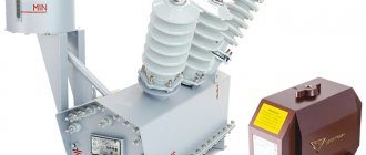
Appearance of frequency converters
Frequency converters are used in the following cases:
- if necessary, change the rotation speed of the electric motor;
- if it is necessary to maintain the value of a process parameter (for example, pressure) by changing the rotation speed of the electric motor;
- no 380V power supply. Frequency converters with 220V power supply are supplied with power up to 2.2 kW inclusive. The engine power is not lost in this case (If the engine has the ability to switch “ star-delta
” 380/220, then it can be turned on from a single-phase 220V network); - connection to an industrial network of motors with a “non-standard” supply voltage and frequency is required.
In addition to the main functions, the inverter provides
- the ability to turn on reverse without additional equipment;
- motor starting current limitation;
- motor current control;
- smooth acceleration and braking (time adjustable);
- additional engine protection;
- possibility of skipping resonant frequencies;
- stabilization of motor torque even with fluctuations in input voltage;
- possibility of stopping with deceleration;
- the ability to save energy with a partially loaded engine (even without a feedback sensor);
- work with built-in timer and counter;
- transition to “sleep mode” with the pump turned off in the absence of water consumption;
- Possibility of automatic restart when power is restored.
All listed parameters (functionality) are supported by ELHART frequency converters of the EMD-MINI and EMD-PUMP series.
Data collected when visiting the site
Personal Information
Personal data when visiting the site is transferred by the user voluntarily, this may include: first name, last name, patronymic, telephone numbers, email addresses, addresses for delivery of goods or provision of services, details of the company that the user represents, position in the company that the user represents, social media accounts; form fields may also request other data.
This data is collected for the purposes of providing services or selling goods, communicating with the user or other user activity on the site, and to send users information that they have agreed to receive.
We do not check the accuracy of the data provided, but we do not guarantee high-quality execution of orders or feedback from us if the data is incorrect.
The data is collected using forms available on the site for filling out (for example, registration, placing an order, subscribing, leaving a review, feedback, and others).
Forms installed on the site can transmit data both directly to the site and to third-party sites (scripts for third-party services).
Data may also be collected through cookie technology, both directly by the site and by scripts from third-party services. This data is collected automatically; the sending of this data can be prevented by disabling cookies in the browser in which the site is opened.
Non-personal data
In addition to personal data, when visiting the site, non-personal data is collected; it is collected automatically by the web server on which the site is located, CMS (content management system) tools, and third-party scripts installed on the site. Data collected automatically includes: IP address and country of registration, the name of the domain from which you came to us, visitors’ transitions from one page of the site to another, information that your browser provides voluntarily when visiting the site, cookies, visits and other data collected by third-party analytics counters installed on the site are recorded.
This data is non-personal in nature and is aimed at improving customer service, improving the usability of the site, and analyzing traffic.
Selection of frequency converter
2.1 Frequency converter for single-phase motor
It is worth noting that standard frequency converters are not designed to work with single-phase motors. Almost all frequency converters on the market are designed to control the rotation speed of a three-phase squirrel-cage induction motor.
More often, when they say “single-phase frequency converter,” they mean a frequency converter powered by a single-phase 220V network. Such a converter has 3 phases of 220V at the output and is also designed to control a three-phase asynchronous motor.
However, frequency converters for single-phase motors exist, but are extremely rare.
Figure 1 - Inverter for a three-phase motor
2.2 Selection of frequency converter by power
When selecting a converter, you first need to focus on the current and supply voltage of the electric motor. This information is indicated on the engine nameplate.
Figure 2 - Engine nameplate
1. Voltage on the windings. The motor, the nameplate of which is shown in Figure 2, is capable of operating at a three-phase voltage of 220V (the windings must be connected in a delta circuit)
) and at a three-phase voltage of 380V (
star
). If the nameplate indicates 380/660, then such a motor can be connected to an inverter with a 220V power supply, but in this case the rated characteristics of the motor will not be ensured.
2. Rated linear current of the motor. This motor consumes 1.44A when connected in a delta (220V power supply) and 0.83A when connected in a star (380V power supply).
The rest of the information given on the motor nameplate does not affect the choice of inverter.
Despite the current indicated on the motor nameplate, the most correct method for determining the operating current is to directly measure it while the motor is running. This will avoid problems if the motor operates at high current. The actual continuous operating current of the motor should not exceed the rated output current of the inverter.
It is not correct to buy a frequency converter based on engine power, since engine power depends on efficiency and power factor ( cosφ
), and the power indicated on the electric motor refers to the mechanical power of the motor on the shaft, and not to the active power consumed from the power source, as is customary for other consumers of electricity.
For example, let’s compare the currents of 1.5 kW motors with the current of inverters of the same power ELHART EMD-MINI – 015 T (1.5 kW, 4A, 380V), ELHART EMD-MINI – 015 S (1.5 kW, 7A, 220V).
Table 1 – Electrical characteristics of motors
| Engine | power, kWt | RPM | Current at Δ220/Y380 V | Efficiency, % | Coef. Power | IP/IN |
| AIR 80 A2 | 1,5 | 3000 | 6,2 / 3,6 | 78,5 | 0,85 | 6,5 |
| AIR 80 B4 | 1500 | 6,8 / 3,9 | 78,5 | 0,80 | 5,3 | |
| AIR 90 L6 | 1000 | 7,3 / 4,2 | 76 | 0,70 | 5,0 |
The AIR 90 L6 engine (1000 rpm), with the same power as the frequency converter, consumes a current of 4.2 A in rated mode with a supply of 380 V, and the converter has a rated output current of 4.0 A.
When connecting the same motor in a triangle
"With a 220 V power supply, the rated current will be 7.3A, and the frequency converter is designed for 7.0A. Therefore, both with a 380V and 220V power supply, the specified motor must be connected to a frequency converter with a power level one step higher (2.2 kW):
- Frequency converter ELHART EMD-MINI – 022 T (2.2 kW, 5 A, 380 V)
- Frequency converter ELHART EMD-MINI – 022 S (2.2 kW, 11 A, 220 V)
Thanks to the frequency converter, it is possible to connect motors with “non-standard” power supply to an industrial network of 220 or 380V. In this case, the main thing is that the rated motor supply voltage does not exceed the inverter power supply, and the rated frequency is maintained by the inverter.
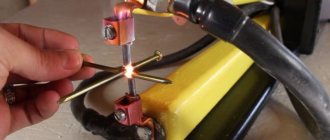
For example, the MSU-200 sheep clipper is powered by an alternating voltage of 36V with a frequency of 200Hz. To work with such a machine, the rated motor supply voltage is set in the settings of the frequency converter - 36V and the rated motor frequency - 200Hz.
Despite the electric motor power of 115W, the operating current is about 3A. In addition to the rated motor current, it is necessary to take into account the amplitude, frequency and duration of possible overloads. In moments of overload, the current of the specified machine can reach up to 7A.
The ELHART EMD-MINI frequency converter can withstand an overload of 150% of the rated current for 60 seconds; EMD-PUMP – 120% for 60 seconds.
Therefore, the rated current of the inverter must be at least 7 ÷ 150% = 4.7A. To connect to a 220V network, select the ELHART EMD-MINI – 007S frequency converter (0.75 kW, 5A, 220V). To connect to a 380V network, select the ELHART EMD-MINI – 022T inverter (2.2 kW, 5A, 380V).
Please note: with a small current margin in this example, the power of the inverter is 6 and 20 times greater than the power of the corresponding motor!
2.3 Choosing between vector and volt-frequency control modes
According to the control mode, frequency converters can be divided into volt-frequency and vector. Let's look at the operating features of these modes.
Volt-frequency (or scalar) control mode of the inverter
- Maintains a constant value of the stator magnetic field at a given frequency (the ratio of supply voltage to frequency is constant). This means that at different speeds the rated torque on the motor shaft will remain unchanged. There are features of operation at low frequencies. Details are described in the section “ Possible range of engine speed adjustment using an inverter”;
- The engine rotation speed depends on the applied load: when the load increases, the engine slows down, when it decreases, it speeds up. With a constant load, the rotation speed does not change;
- Allows you to operate multiple motors simultaneously (to operate multiple motors, additional current protection must be provided for each motor).
Vector control mode of the inverter:
- maintains a constant rotation speed under changing loads (due to automatic adjustment of the output voltage);
- operates more stably at low frequencies (by compensating for the voltage drop in the motor windings).
Features of vector mode:
- it is possible to change the rotation speed at a constant load within 2Hz (due to the search for the optimal voltage). This is normal and not a malfunction;
- Can only work with one motor (does not support multi-motor mode);
- works correctly if the engine's passport data is entered correctly and its autotest has successfully passed.
Both volt-frequency and vector control modes, in the presence of a built-in PID controller, are capable of accurately maintaining a process parameter based on a feedback sensor (speed, pressure, humidity, temperature, and others).
As a rule, for most applications, using the voltage-frequency mode is sufficient. Such applications include pumps, fans, conveyors, woodworking machines, high-speed milling machine spindles, simple cutters, presses, packaging machines, filling machines, dispensers, compressors and other equipment.
Vector mode is usually used when working with lifting and transport mechanisms, crushers, drilling equipment and other loads where high torque is required in the low frequency range and at startup, and there is no clear dependence of the load torque on the rotation speed.
2.4 Supported frequency converter control methods
Since the frequency converter is usually installed in a control cabinet, to access the built-in panel it is necessary to open the cabinet door each time (if you work in a dusty industry - flour, dust, cement - frequent opening of the door is unacceptable). In addition, often the inverter is installed next to the engine, and the operator's console is located to the side.
Using the EMD-Mini remote control panel - RCP (not included in the delivery package), you can implement remote control of the EMD-Mini frequency converter at a distance of up to 2 meters. The remote control has exactly the same functions and capabilities as the control panel on the frequency converter itself.
In ELHART frequency converters of the EMD-PUMP series, the built-in remote control is removable and can be removed using the included two-meter cable.
To remotely control engine starting and stopping using buttons and switches, discrete inputs are required.
The presence of an analog input allows you to remotely smoothly adjust the speed using a potentiometer or an analog signal 0...10V/4...20mA
. Together with the built-in PID controller, the analog input allows you to continuously maintain the value of the process parameter (pressure, flow, temperature, etc.)
RS-485 interface
or
RS-232
allows you to connect to the upper level of the process control system.
Program mode allows you to change the speed and direction of rotation according to a predetermined program.
2.5 Selection of frequency converter for the pump
Special attention should be paid to frequency converters of the pump series. What distinguishes them from other converters is the inherent algorithm for working with several motors. Namely: alternating engines and cascade mode. The alternation mode is used to ensure uniform wear of the engines. Cascade mode is used when it is necessary to control several pumps using one frequency controller. The peculiarity of the cascade mode is that a low-power frequency converter is capable of regulating productivity or pressure over a wide range, including the minimum required number of pumps. ELHART EMD-PUMP frequency converters can control a group of 2 to 7 pumps
. It is possible to work with pumps of different powers; in this case, the power of the inverter is determined by the most powerful pump.
2.6 Additional equipment
In some cases, when using a frequency converter, it may be necessary to install additional equipment:
- A braking resistor is needed to dissipate the energy supplied to the inverter from the motor, which operates in generator mode. The braking resistor is used to ensure a quick stop or deceleration of the engine (especially with high-inertia loads), when working with lifting and transport mechanisms (cranes, elevators, inclined conveyors, elevators), high-inertia applications (smoke exhausters, centrifuges, roller tables, draft mechanisms, transport carts) , in applications where positioning accuracy is important.
- The motor choke is installed when the distance between the motor and the converter is more than 30m; protects the motor from pulse currents, reduces interference, limits the amplitude of short-circuit current, reduces the rate of rise of short-circuit current and, as a result, improves the protection of the converter from short-circuit.
- The mains choke is connected to the input of the converter and is a two-way buffer between the power supply network and the frequency converter. Protects against peak voltage surges in the network. Installation of a network choke is recommended in case of unstable network parameters (ripple, voltage dips), when phase imbalance is more than 3%, if the power of the power source (distribution transformer) is more than 500 kVA and exceeds the power of the converter by six or more times, or if the cable length between the power source and IF less than 10m. The use of network chokes significantly increases the service life and reliability of frequency converters.
Features of choice for different equipment
The choice of a frequency converter largely depends on the conditions of use of the device and on the purposes for which it is selected.
For pump
In this case, a frequency converter is needed to protect the pipeline from water hammer when starting the pump, and the engine from failure and operation in emergency mode. To do this, the inverter must provide a smooth start of the pumps and a smooth change in the rotation speed of the electric motor.
It is important that the converter can regulate pump performance, maintain constant pressure in the water supply system and optimize energy consumption by controlling dry operation - automatically stopping a running pump when there is no water flow.
An algorithm for working with several engines is also useful: alternating or cascade mode. When alternating, pumps are used one at a time to ensure even wear on the engines.
Cascade mode is used when you need to control several pumps with one inverter. A low-power frequency generator regulates productivity or pressure, turning on only the required number of pumps. In this mode, you can work with pumps of different power, then its value at the converter is determined by the most powerful pump.
For lifting equipment
Modern crane equipment and winches are complex mechanisms. Therefore, a frequency converter for an electric drive of such a device must have maximum overload capacity, be able to control the mechanical motor brake and have its own built-in braking resistor.
It is important to choose a model with the ability to receive feedback from an electric drive. This is necessary for the rapid exchange of information between parts of the system, continuous monitoring of all processes and precise control of parameters during operation.
A properly selected frequency converter ensures reliable control of the crane's electric motor, moving loads at different speeds without swinging and providing maximum productivity.
For conveyor equipment
When starting such equipment, there is an increased load on its parts and a starting current that exceeds the rated current by 6–7 times. This leads to increased wear of components or overheating of the electric motor, which is the most common cause of failures and breakdowns of such equipment.
For conveyors, smooth acceleration and braking without jerking, slipping, stopping, as well as the same set speed are very important. Therefore, for this type of device you need to choose a frequency converter that automatically regulates the belt speed, eliminates overloads during startup, and removes excess energy during braking using a special module.
Such a frequency regulator will increase the level of reliability and extend the life of the equipment.
Motor speed control range when using a frequency converter
3.1 Using an inverter to reduce motor speed
To operate at low frequencies (below 10-15 Hz), special attention must be paid to motor cooling and shaft torque.
Enclosed fan cooled motor ( TEFC)
) has cooling only due to the built-in fan. The performance of the cooling fan decreases in proportion to the engine speed. When engine speed is reduced, cooling efficiency decreases, which leads to engine overheating and possible failure.
There are several options for cooling the electric motor when operating at low frequencies:
- reduce the period of continuous operation of the engine at low frequency
- organize additional cooling;
- reduce the load on the motor shaft;
- install a reduction gearbox, which will increase engine speed;
- use a larger motor.
The volt-frequency control method allows you to maintain a constant torque on the motor shaft at different speeds. When operating at low frequencies (below 5-10 Hz), the torque on the shaft will depend on the characteristics of the specific motor (active resistance of the windings). To maintain torque at frequencies below 5-10 Hz, it may be necessary to adjust the minimum voltage of the U/f
. Increasing the voltage value will cause an increase in starting torque, but will also lead to an increase in current consumption, and in proportion to the increase in flowing current, heating increases. Recommended frequency control range for voltage-frequency control: 5-50 Hz. The ELHART EMD-MINI frequency converter supports frequency adjustment from 0.5 to 999.9 Hz.
The vector control method is able to more accurately maintain torque at low frequencies (especially with changing loads). The range of possible adjustment is wider than that of the volt-frequency mode and depends on the specific model (company, series) of the inverter. For vector control, it is recommended to use Delta Electronics frequency converters of the VFD-E and VFD-C series.
To increase the starting torque, it is recommended to use a frequency converter of higher power (since the converter can only provide the motor with one and a half times the current (rated current × overload capacity of the inverter).
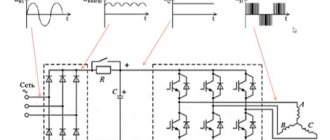
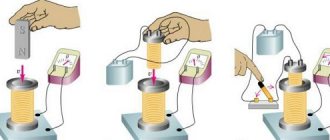
Common regulator circuits
There are many frequency converters for asynchronous motors, as well as various regulators for them. It is possible to independently make a device for adjusting the frequency using transistors or thyristors. The device works both in everyday life and for machine tools, crane mechanisms, and various adjustable drive units.
A powerful frequency and voltage regulator is shown in the diagram. The device smoothly changes drive parameters, saves energy, and reduces maintenance costs.
To apply this scheme in everyday life, it is difficult. If you use a triac as a working element, the circuit is simplified and looks different.
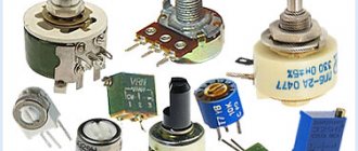
The adjustment will take place by operating a potentiometer, which determines the phase of the input pulse and opens the triac.
The effect of operating machines that process metal and lifting devices also follows from the rotation of the engine, as do its operational parameters themselves. There are many devices on sale for adjusting frequency, but it is quite possible to assemble such a device on your own.