The simplest and most uncomplicated device that allows you to automate various actions is a 220 V time relay with a turn-off delay. Changing advertising on signs, controlling watering systems, turning on devices at a certain time, supplying electricity, water - all this and much more can be done using such a simple device. Modern relays are easy to set up operating modes and allow them to be performed even by people who are not technically savvy.
How to choose?
When choosing a specific time relay model, you must be guided by the following principles regarding their parameters:
- Type and value of operating voltage - various models can either be connected to a household network of 220 V AC, or operate from reduced control circuits of 12, 42, 127 V, etc.
- Allowable load current – determines the capacity of the time relay contacts without overheating.
- The range of contact response times and the sensitivity of adjusting this parameter determines the speed at which the time relay is switched on, the possibility of changing it within any limits and the possible adjustment step.
- Design features and principle of operation - if local conditions do not allow classical switching of contacts for reasons of explosion hazard, it is necessary to install contactless models.
- Moisture resistance and temperature range - determines the permissible environmental parameters in which this time relay can be operated.
- Type of device (cyclic or intermediate) - the first of them sets a certain periodicity of the output signal, and the second acts as an intermediate link that provides a time delay in an already existing circuit.
Convenience of homemade products
There are practically no situations where users are forced to make a temporary relay with their own hands due to the lack of a suitable device for sale for their needs.
All kinds of timers, or rather modules, installation kits, if we consider this issue close to home-made products, can be purchased on Internet sites. For example, the price of the NE555 analogue assemblies we describe ranges from 1 to 3 dollars. Is it worth the bother? In addition, you can choose a device with a wide range, with multiple channels, multi-function and with a display; for low-current power supply 5, 12, 24 V, etc., as well as 220 Volt.
It is advisable to do homemade products if you have the necessary spare parts on hand, the user has skills in working with electronics, and even when you do not want to order and wait for a form when they are not available in radio parts stores in the area. In addition, crafts are often created based on interests, in order to increase experience and knowledge in this area.
Programming microprocessor devices
As described earlier, microprocessor devices became a milestone in the development of time relays. The essence of what they are needed for is the versatility of the device. It can be programmed to perform the functions of turning off, turning on, maintaining line activity for a set period, and all of the above can be done without changing the design of the device itself. Any complexity of operations will be performed using just one microcircuit located on the device board.
In addition to these features, a nice bonus is the expansion of functionality through communication interfaces with smart home systems. The latter can not only monitor the state of the time relay, but also set its parameters or directly influence the shutdown mechanisms.
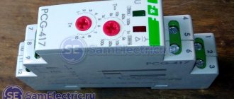
For example, a universal two-channel programmable time relay UT24 from the Aries production association is shown in the picture below:
To program its timers, you need to refer to the block diagram and follow the steps; you can find out the purpose of the configured item in the user manual, which comes with each device:
As you can see, microprocessor devices seem complex only at first glance, but once you understand a little, you can easily use them for your purposes and configure them.
Self-production
If you wish, you can make a timer for turning on and off electrical appliances with your own hands. Before you begin, you need to decide on the tasks, find the device diagram and the required radio components. Schemes exist of varying degrees of complexity.
Transistor relay circuit
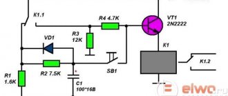
A simple 12 V turn-off delay relay circuit is assembled on a single transistor and does not contain scarce parts. This is a very easy to follow pattern. After assembly, no configuration is required. Such a device will work no worse than one purchased in a store.
Any npn conductivity transistor is used as VT1. When power is applied, the capacitor is charged. When the voltage threshold is reached, the transistor opens and relay K1 is activated. By changing the value of C1 and R2, the on time is adjusted. The switch-on delay in this design reaches 10 seconds. In order for the relay to remain closed for some time when the power is removed, a large capacitor is installed in parallel with the power supply to the circuit.
On-chip delay control
A simple circuit for controlling a light, fan, or other load can be assembled on the NE555. The NE555 specialized chip is nothing more than a timer. The output current of the device is 200 mA, the current consumption is 203 mA. The timer error does not exceed one percent and does not depend on changes in the signal in the 220 volt network.
The circuit operates from a constant voltage source. The circuit power signal level is selectable in the range from 9 to 14 Volts. A chain consisting of resistors R2, R4 and capacitor C1 sets the delay time. You can calculate this time using the formula t = 1.1*R2*R4*C1. After pressing the SB1 button, contacts K1.1 are closed. After time t they will open. In order for the timer to start counting time not from the moment the button is pressed, but at the moment it is released, you will need to use a button with normally closed contacts.
The adjustment time can be easily adjusted using variable resistor R2. It is convenient to assemble such a circuit on a board made of PCB or getinax. After correct assembly and with working radio components, the circuit works immediately.
Purpose, types and principle of operation
A time relay is a device designed to automate actions depending on a set time interval. In other words, the device allows you to delay the start of the process for a certain period of time. Structurally, the device consists of the following parts:
- manager;
- withstanding;
- executive.
The control part will ensure startup when an enabling signal appears on the circuit elements. The withstanding part puts the device into pause mode, and the executive part directly switches the load connected to the output.
A simple time relay with a 220 V switch-on delay is designed to control a time delay, for example, turning off the light five minutes after it is turned on. The most common types of relays are: electromechanical, electromagnetic, programmable.
In simple cases, the first two types of relays are used, using one setting. The programmable type has advanced capabilities. Its main ability lies in the ability to create cyclical action and flexibility of configuration. Thanks to this, such a relay is universal for any application and can be adjusted with high accuracy. It can be controlled remotely, equipped with a convenient indication system, and also used in circuits instead of a pulse relay.
According to the method of arrangement, they are divided into free-standing, built-in and modular. Stand-alone devices are independent devices housed in a separate housing with an external power supply. For example, a time relay for photo printing. Embedded devices consist of a board and a mechanism without a housing. They form a single whole with other complex devices, for example, a timer-programmer in a microwave oven or a surface-mounted switch with a time delay. Modular devices are produced with fastenings made for DIN rails, and they are intended for placement in switchboard cabinets.
Electromagnetic device type
Used in DC line. The advantage of electromagnetic relays is their low price, but the disadvantage is their limited operating life. The main parts that make up the device are:
- coil;
- magnetic circuit;
- anchor;
- traverse;
- spring.
Between the armature and the core there is a magnetization-resistant gasket. Its main purpose is to protect the armature from contact with the core. The movement of the armature in the coil is created by a magnetic field as a result of the passage of electric current through its turns. If there is no gasket, then the spring will not overcome the effect of residual magnetization and the moving contacts on the traverse will not open. The thickness of the gasket affects the response delay time.
The time delay is adjusted by setting the spring tension value. For this purpose, an adjusting screw is provided in the design. The time delay is accomplished by short-circuiting or disconnecting the relay coil.
When the coil is short-circuited, the magnetic field disappears or reaches a small value. After turning off the power supply, due to the closure of the coil, self-induction is formed in the circuit, maintaining the current value for some time. The magnetic field, and therefore the force holding the armature, begins to gradually decrease.
In order for the magnitude of the magnetic field to slowly decrease when the coil is turned off, so-called dampers are used, forming a secondary circuit. The material for their manufacture is copper or aluminum. When the magnetic field disappears, a current is induced in the damper; the smaller its mass, the shorter the holding time. Using different removable dampers, the delay time is also changed.
Relay with pneumatic and anchor delay
The main part of this type is the electromagnet. It applies to both direct and alternating current. A pneumatic damper or sentry is used as a delay device. The advantage of this method of operation of the device is its independence from the shape of the power signal and the ambient temperature. The main element of the anchor structure is a spring, the degree of compression of which is controlled by an electromagnet. Pneumatic relays allow you to adjust the time in the range from 0.4 to two minutes with an accuracy of ten percent. For anchor devices, the pause time ranges from 7 to 20 seconds with the same accuracy.
In addition to the electromagnet, the pneumatic relay contains:
- pneumatic retarder;
- block;
- rubber diaphragm;
- adjustment needle.
The electromagnet, when activated, lowers the block under spring pressure. The lowering speed depends on the diameter of the hole, through which air enters the upper part. By changing the air supply speed and adjusting the hole size, the delay time is also changed.
Motor type devices
The devices allow you to switch powerful loads. The accuracy of operation is five percent, and they can perform more than 1 thousand operation cycles. The delay time reaches 30 minutes. The design uses an electric motor with adjustable speed. When power is supplied to the engine, it starts; rotation is transmitted through the clutch to the discs with cams. The latter act on the output terminals.
Depending on the location of the cams, the contacts are closed or opened. The delay time is determined by the initial position of the disks. As soon as the power is lost, the disks return to their original state under the action of a return spring. The return time does not exceed a second.
Electronic time delay
Digital devices are the most functional and common types of relays. Their advantage is digital signal processing, which allows for a high degree of accuracy. Such time relays are produced with a turn-off delay for 12 V, 24 V, 220 V and other values. The operation of the device does not depend on changes in the magnitude and frequency of the input signal. This type of device is the safest to use , since it is galvanically isolated from the power circuit.
The operating principle is based on the use of transient processes in resistive-capacitive and inductive circuits. To generate the delay, specialized microcircuits are used that allow timers to be programmed. Programming a timer comes down to setting the time. It can be analog or digital.
By controlling the voltage across the capacitor, a time interval is formed. It is equal to its value from the moment the signal is applied to the chain until the required voltage level is reached on the capacitor. The capacitor discharges according to an exponential function. To increase the delay time, a self-oscillating circuit is used, and the degree of accuracy is achieved by adding quartz to the circuit. A device with short time delays is performed on the basis of one charge-discharge cycle, and with longer ones it is performed on the basis of several.
To obtain the voltage required for various parts of the circuit, a converter is located at its input. In addition, it forms the reference voltage level. Thus, in digital relays, the time delay is set by the charge-discharge circuit and the comparator. Counting the number of generator pulses and changing the time value is carried out using a counter. Receiving impulses from the generator, the meter counts them. The decoder analyzes the state of the counter and generates a signal sent to the executive unit.
Time relay for automatic load shedding
Sometimes it is necessary to turn off the receiver or backlight after a certain period of time. This problem can be solved by the circuit shown in Fig. 1.
Rice. 1. Timer circuit for automatic load shutdown.
With the ratings of the timing elements indicated in the diagram, the shutdown delay will be about 40 minutes (for micropower timers, this time can be significantly increased, since they allow R2 to be set with a higher rating).
In standby mode, the device does not consume power, since transistors VT1 and VT2 are locked. Switching on is done by button SB1 - when pressed, transistor VT2 opens and supplies power to the microcircuit. At the output of timer 3, a voltage appears, which opens the transistor switch VT1 and supplies voltage to the load, for example, to the BL1 lamp.
The button is blocked, and the circuit will remain in this state while capacitor C2 is charging, after which it will turn off the load. Resistor R3 limits the discharge current of the timing capacitor, which increases the reliability of the device. To obtain large delay intervals, capacitor C2 must be used with a low leakage current, for example tantalum from the K52-18 series.
Timer with extended time interval
A diagram of a device for a similar purpose is shown in Fig. 2. It allows you to discretely change the load shutdown delay time from 5 to 30 minutes (in steps of 5 minutes) using switch SA1. Thanks to the use of a micro-power timer with a high input resistance, it is possible to use timing resistors of significantly larger values (from 8.2 to 49.2 MOhm), which allows the time interval to be increased: T = 1.1 * C2 * (R1 + ... + Rn).
Rice. 2. Timer circuit with an increased time interval to disconnect the load.
What else is important to know? 2 interesting facts
3T=RC
The considered formula T=RC has a certain peculiarity. Time T is only 63% of the maximum charge, 95% is 3T.
Voltage versus time
During discharge, an inversely proportional relationship occurs. During time T, the capacitor will discharge to 37%, after 3T to 5% of the maximum. This happens because with an increase or decrease in the internal charge, the potentials gradually equalize.
That is, let’s assume that in 10 seconds the condenser is charged to 95%. Charging voltage 10V, circuit resistance 10Ohm, current 1A. At the seventh second, the voltage in the circuit will drop by 30% and become 7V. This happens because the potential begins to equalize as the capacitor charges. Consequently, the current in the circuit will also drop by 30% - to 0.7A. And this will happen until equilibrium is established in the chain.
AC voltage
Sinusoidal voltage has several phases. At the peak of the ascent, when the half-cycle ends, the current reaches its maximum value. This peak shows the peak current, the maximum instantaneous value of the alternating current, which is 1.4 times higher than the rms value. That is, the 220V alternating current we are considering at some point in time reaches a peak of 308V.
Simple time relay for 220 V
This time delay relay is 220 Volt
is not galvanically isolated and is the simplest.
A thyristor
is used as a switching element .
As we said, a thyristor allows you to switch a load that is insensitive to the shape of the supply voltage: an incandescent lamp, a shadow lamp, a halogen lamp, and the like.
You cannot connect an LED driver or an energy-saving CFL type, or any electronic device that has a transformer at the input.
The minimum details of the circuit and the simplicity of the circuit will allow anyone to assemble this circuit, spending no more than 50–100 rubles.
The circuit works as simply as it looks. If you close contact S1, then gradual charging of C1 will begin. During the charging of this capacitor, thyristor VS1 will be open.
Load HL1 will have mains voltage. As soon as the capacitor is charged, thyristor VS1 will close and current will stop passing through it. Our device will shut down and the load will turn off.
The diagram contains the following details:
diode bridge, which performs the function of supplying rectified current to the thyristor: consists of diodes with a maximum current of not less than 1A and having a reverse voltage of not less than 400V (1N4007);
thyristor series BT151 (if you have KU 202N or KU 202M lying around, use it);
- resistance
R1 – 4.3 MOhm, power 1 W; - resistance
R2 200 Ohm, 1W; - R3
of the same power, 1.5 kOhm; - capacitor
C1 is 0.47 µF, 630V or higher voltage; power no more than 200 W; When using incandescent lamps, including halogen lamps, remember that the starting current when turned on can be 10 times higher than the operating current, although this does not last so long. - switch
or toggle switch S1.
Since the whole principle of operation of this relay comes down to charging the capacitor, changing the capacitance of the capacitor
The easiest way is to change
the relay switching time
.
Due to the simplicity of this device, it is impossible to give a simple formula for calculating the holding time, since the time depends on the parameters of a particular thyristor, resistor resistance, and capacitance of the capacitor.
On the chip
Disadvantages of the mentioned transistor time relays:
- short and incomprehensible delays;
- the need to restore the capacitor charge for subsequent activation;
- difficulties arise in determining the duration.
The shortcomings will be partially eliminated if a microcircuit (microcontroller, abbreviated as MK) is integrated into a home-made product, which allows you to install a gap - NE555 or similar. The initial letters of the specified MK can be LM and others. This is a time module that allows you to regulate the pause with a variable resistor, that is, more precisely assemblies (discussed above).
There are several options for creating a time relay on an MK. We chose the first NE555 product with protection (R4) that prevents the variable resistor from “unscrewing”.
Basic circuit on LM555
Deactivating the relay ensures automatic switching of the resistor, only that it is closed by a signal from the output of the microcircuit, after counting the required seconds.
The designations in the diagram are deciphered in the options described above; we will remind you of them as we describe the stages of making homemade products. R2 and 4 (if any), C1 set the duration of pauses. Activation of the “micrik” - SB1 - closes K1.1 and turns off after a certain period of time. Then you can press SB1 again. Delays are calculated using the formula:
Multiplication by R4 is added to the formula if such a resistor is installed. The relay is suitable for a wide range of loads from 9 to 14 V.
Push-button microswitch and resistors (possible with relay):
Variables (R2) are produced in various standard sizes, all are suitable, the nominal value is taken according to the delay of the minimum and maximum value:
Capacitor C2:
The 555 time relay unit operates from a power supply with a mains transformer, through a diode bridge, capacitors, and there is no parametric stabilizer. All parts can be connected to each other on site or without.
Improved version
The above circuit has disadvantages: it is susceptible to interference, the relay does not turn off if the amplitude of the input pulse exceeds the delay. The second option on NE555 is more advanced, transistorless, resistant to interference, and the like. This solution simplifies and reduces the cost of homemade products, reduces the number of elements, increases the maximum output current, so that the relay windings can be connected directly to the output.
The homemade product is based on relay K1 connected to the output. The maximum current of NE555 exceeds 100 mA, which allows you to connect it directly if its winding consumes less, and if more, you need a suitable transistor. You will need VD1 - a reverse diode. Low noise immunity is a consequence of the presence of two 555 comparators, half of the pins are switched off, the rest are connected to internal high-resistance resistors.
Pin operation:
- 6 – connected to the RC circuit (as it was) – the voltage is clearly set on it;
- 5 – for reinsurance, it is allowed to connect up to three low-resistance external resistors, which will slightly increase noise immunity;
- 2 – standardly connected through a resistor to the power source “+”, then through the ground button (“-”). This will not create an incorrectness, because when the button is not pressed, the voltage at N 2 is compared with the supply voltage, and when N 2 is pressed it = 0.
- 2, 5, 6 go out - the voltage is set as desired, the other one remains inside, but interference is unlikely to affect the timer;
If a cable that is too long goes to pin 2, it will cause interference and create voltage that is not needed. Thus, the gap from N 2 to the button or node that creates the correct value on it is reduced as much as possible and a resistor is selected that “pulls” this pin to “+” with the minimum possible resistance, but not so. The strong thing is that a short circuit occurs when a button is pressed or when the voltage drops to 0 in this place. In the first scheme, this parameter was 100 Ohms (more for lower power consumption), in the considered option - 4.7 kOhms. That is, as low as possible to increase noise immunity, it is allowed to be placed even lower, for example, if there is an induction furnace and similar devices nearby.
Another drawback is eliminated by capacitor C1, and optocoupler U1 is provided for galvanic isolation of the control circuit and relay, which will also improve noise immunity. When its LED is strongly activated and the transistor opens, the voltage at the collector quickly drops: its low value is created at N 2 for a short time. Upon completion of charging of capacitor C1, the value becomes equal to the parameter of the power source, and even if the transistor is always open, the input pulse to the circuit is still short, the relay turns off after a pause period.
After closing transistor C1 with a short pause, which discharges through R1 and 2 (resistors), it will be possible to reactivate the timer.
The circuit of the relay of the same name is implemented on a board made of double-sided fiberglass, on one side there are traces of all the elements, on the other it is left empty, 0 (minus) is soldered to it, which is connected to pin 1 of 555, which will further increase stability. It is recommended to move the trip pins as far away from the circuit as possible, then solder them on a separate board (not 555).
Additional parameters on NE555
The following diagram is much simpler and clearer than the previous ones. It can be turned on or off.
As you can see, there are 2 buttons:
- launch – “start”;
- up – “stop”.
Control - resistance R1 and cond. C1, the pause depends on their parameters, in this case its interval is 2 seconds. – 3 minutes Power supply – 12 V.
Example of a working home product
The circuit is powered by 9 V. Activation - the “Start” button, the HL1 LED lights up, after the interval - HL2. A variable on the timer adjusts the delay. This handmade product is used by the user to heat up car mirrors. If you build a power relay, you can connect anything.
The next option is a little more complicated, but overall also elementary:
Type of finished assembly (there are similar factory modules):
Based on TL431
Elements (features on the diagram):
- TL431 controller;
- "Mikrik";
- capacitor (C1, selected experimentally);
- resistors - 3 pieces (in diagram R);
- e/m relay (executive unit).
The relay contact is connected in parallel to the Mikrik, to it - “+” from the power source; the second is carried out on a 100 ohm resistor, also connected to the resistors. Pins 2 and 3 of the microcircuit are connected to a 100 Ohm resistor and a diode. The last contact of the timer is a semiconductor with an actuator unit (e/m relay). Negative power – with a resistance of 510 Ohms. Feature of the circuit: the capacitor is discharged automatically; further ignition of the “micrika” SB1 is not required.
Timer for daily activation of microcircuits CD4060B, CD4001
The circuit is assembled on the basis of 2 pulse generators with a frequency range of 24 hours, and also includes a trigger and an output switch with a relay. Power supply: “recharges” a smartphone, a mobile phone at 5 V. A backup source may be provided (in the variant under consideration there is none). The generators are built on CD4060B microcircuits with a 14-bit binary counter (they do not have pins 1 to 3 and 11 bits) and 2 inverters (one connected to the counter input) for a multivibrator circuit connected in series.
The multivibrator frequency is set by RC circuits C1-R2 and C4-R7, and by selecting the resistances of resistors R2 and R7, the pulse repetition rate is set to 24 hours. Reaching the logic drive at pin 14 occurs after 2 minutes. 50 seconds after pressing S1 (S2). Then the resistance is selected more accurately, this interval is made equal to 1 minute. 15 sec., At the last stage, daily adjustments are made.
Idea 1. On diodes
Let's consider a version of the simplest logical element for operation in a 220V circuit.
Rice. 4. 220V time relay circuit
Here, switching on occurs when button S1 is pressed, after which voltage is supplied to the diode bridge. From the bridge, the potential passes to a timing element consisting of resistors and a capacitor. During the process of accumulating charge, the thyristor VS1 will open and current will flow through the lighting lamp L1. When the capacitor is fully charged, the thyristor will go into the closed state, after which the relay will operate and the lamp will stop burning.
The maximum shutter speed here can be set to several tens of seconds, since its value will be set by the resistor resistance and capacitance. A significant drawback is that this scheme poses a threat to human life in case of electric shock. Therefore, next we will consider an example of manufacturing a 12V time relay.
Video on the topic
Post navigation
"Installing a circulation pump in the heating system. Connecting a humidity sensor to Arduino"
Time relay with switch-off delay
Date: March 03, 2022 | Section: Works from readers
Hello, dear readers of the site sesaga.ru. After reading an article about a time relay with a turn-on delay, I tried to assemble a relay circuit with a turn-off delay for a fan in the toilet and I did not like the transformerless power supply circuit with two diodes and a quenching capacitor used in the article. Since the circuit turned out to be very power-hungry and consumed quite a lot of current for its own power supply, I installed a diode bridge, which allowed me to reduce the power consumption to 10 W (the total power consumption of the time relay depends on the type of relay used).
Attention! This design has transformerless AC power supply. When assembling it, pay special attention to compliance with safety precautions when working with electrical installations
.
The operating principle of a time relay is simple. When closing the contacts of button S1
(without latching) power is supplied to the circuit through a transformerless power supply and the NE555 timer is turned on.
Transistor VT1
, relay
KL1
and blocks the contacts of button
S1
, leaving power to the time relay circuit and the fan turned on for the duration of the specified shutdown delay.
As capacitor C3
to a level equal to 23 supply voltage, the timer will switch to the off state, relay
KL1
will de-energize and with its contacts
KL1.1
will disconnect the circuit and the fan from the network. This ensures zero current consumption in standby mode.
In general, the time relay works perfectly and does not consume current when it is off. I drew the signet in lay format based on the available details. To connect the wires, I used a self-clamping connector from a burnt-out fluorescent lamp ballast such as 2x36 electronic ballasts and the like, which is very convenient when installing low-current circuits, the main thing is quickly. Timer 555 is used in an SMD case, and the S1 button is taken from an apartment bell.
The archive of the printed circuit board in lay format can be downloaded here
link.
I wish you success in repeating the design! See you! Yuri, Vitebsk.
If you liked the article, share it with your friends:
What are timers, pause relays, delays
Let’s make a reservation right away: homemade auto-timers adjust the delay from a few seconds to 10–15 minutes. There are schemes only for incl. and for on/off load, as well as for activation at certain times of the day. But their delay range and options are limited; there is no function of periodically operating independently several times and adjusting the intervals between such cycles, like in factory outlet devices. However, the homemade capabilities (there are also ready-made similar simple modules on sale) are enough to activate garage ventilation, lighting in the pantry and similar not too demanding operations.
A temporary relay (timer, pause, delay relay) is an automatic release that is triggered at the moment set by the user, turning on/off (closing/opening contacts) of an electrical appliance. The timer is extremely practical in situations where the user needs the device to be activated or deactivated while he is in another location. Also, such a unit will help out in ordinary everyday situations, for example, it will protect you when you forget to turn off/on the equipment.
Thus, the temporary relay will eliminate situations where you left an electrical appliance on, forgot to turn it off, and, accordingly, it burned out or, even worse, caused a fire. By turning on the timer, you can go about your business without worrying about having to return at a certain time to service the equipment. The system is automated, the unit itself will turn off when the set period on the release has expired.
Where is it used?
Many people are familiar with the clicking sounds in Soviet washing machines, when large graduated selectors set a certain delay before turning on/off. This is a vivid example of this device: for example, they set it to work for 10–15 minutes, the drum spun for this time, then, when the clock inside reached zero, the washing machine turned itself off.
Manufacturers always install temporary relays in microwave ovens, electric ovens, electric water heaters, and automatic watering systems. At the same time, many devices do not have it, for example, lighting, ventilation (hood), then you can buy an additional timer. In its simplest form, it looks like a small rectangular block with time selectors and a plug for a regular socket (“daily” timer sockets) into which it is inserted. Then the power cable plug of the device being serviced is inserted into it, and the delay time is adjusted using the controls on the body. There are also standard sizes for placement by connecting to a line (with wires, wiring, for switchboards), for integration inside devices.
Device, types, features
Mostly timers in factory electrical appliances with trip units are based on a microcontroller, which often also controls all operating modes of the automated device where they are installed. The described combination of functions is cheaper for the manufacturer, since there is no need to manufacture separate microcircuits.
We will describe the simplest time delay relay circuits, only with an on/off option. and selecting a time pause in a small range (up to 15–20 minutes):
- for low-voltage power supply (5–14 V) - on transistors;
- on diodes - for power supply directly from a 220 Volt network;
- on microcircuits (NE555, TL431).
There are special factory modules, they can be bought on online sites (Aliexpress, similar and specialized resources), on radio markets, in special stores. Completely handicraft products are created according to similar schemes, mainly for simple tasks: elementary disengagement/coupling of contacts at a certain, specified point in time, while the delay range is small from seconds to 15–20 minutes.
What type of device is better to choose?
Before making a purchase, describe your requirements for the device. Taking these factors into account, it is worth looking for a suitable switch. Decide where the switch will be installed - outside or built-in. Then decide what functions interest you as the owner of the device. If you need to activate additional functionality, you will have to buy some sensors. Or choose a modification in which all elements are already part of the structure.
When choosing, it is recommended to follow these points:
- Consider the voltage for which the product is designed to operate.
- Decide on the type of control - mechanical or digital.
- Place of installation - in a socket, socket box, distribution box.
- Consider the operating conditions and whether protection from moisture is necessary.
Also take into account the frequency indicated on the switch timer.
If the functions are supposed to be carried out several times a day, then it is worth choosing daily models. There are also options for a weekly or monthly timer to choose from. A more complex modification of the device is suitable for controlling several devices and power lines. When choosing a manufacturer, you should pay attention to models from well-known and trusted brands. Often positive reviews are left about switches from Legrand, Feron, Livolo, Orbis.
The use of a switch with a delayed shutdown will open up new possibilities for you. It is worth combining the product with the “smart home” option. This approach will ensure comfortable living conditions and at the same time save resources. Thanks to a clearly defined interval, homeowners do not have to worry if they forget to turn off the lights. For them it is to make the device at a certain time. Increased security measures in the modern world have long become the norm. All you have to do is decide on a model that suits your needs, because why overpay for functionality that may never be useful. Once you familiarize yourself with the variety of models, it will be easier to choose the right option. At the same time, study the technical characteristics of the switch with a shutdown delay, study the rules for programming the device. It would be good if it could function during a power outage.
How does the 555 chip work?
Before moving on to the example of a relay device, let's consider the structure of the microcircuit. All further descriptions will be made for the NE555 series chip manufactured by Texas Instruments.
As can be seen from the figure, the basis is an RS flip-flop with an inverse output, controlled by outputs from comparators. The positive input of the upper comparator is called THRESHOLD, the negative input of the lower one is called TRIGGER. Other comparator inputs are connected to a supply voltage divider consisting of three 5 kOhm resistors.
As you most likely know, an RS flip-flop can be in a steady state (it has a memory effect of 1 bit) either in a logical “0” or in a logical “1”. How it works:
- The arrival of a positive pulse at input R (RESET) sets the output to logical “1” (namely “1”, not “0”, since the trigger is inverse - this is indicated by the circle at the trigger output);
- The arrival of a positive pulse at input S (SET) sets the output to logical “0”.
Three 5 kOhm resistors divide the supply voltage by 3, which leads to the fact that the reference voltage of the upper comparator (the “–” input of the comparator, also known as the CONTROL VOLTAGE input of the microcircuit) is 2/3 Vcc. The reference voltage of the lower one is 1/3 Vcc.
With this in mind, it is possible to create tables of states of the microcircuit regarding the TRIGGER, THRESHOLD inputs and OUT output
Note that the OUT output is the inverted signal from the RS flip-flop
| TRIGGER < 1/3 Vcc | OUT = log "1" | undefined state OUT |
| TRIGGER > 1/3 Vcc | OUT remains unchanged | OUT = log "0" |
In our case, to create a time relay, the following trick is used: the TRIGGER and THRESHOLD inputs are combined together and a signal is supplied to them from the RC chain. The state table in this case will look like this:
| THRESHOLD, TRIGGER < 1/3 Vcc | OUT = log "1" |
| 1/3 Vcc < THRESHOLD, TRIGGER < 2/3 Vcc | OUT remains unchanged |
| THRESHOLD, TRIGGER > 2/3 Vcc | OUT = log "0" |
The NE555 connection diagram for this case is as follows:
After power is applied, the capacitor begins to charge, which leads to a gradual increase in the voltage across the capacitor from 0V onwards. In turn, the voltage at the TRIGGER and THRESHOLD inputs will, on the contrary, decrease, starting from Vcc+. As can be seen from the state table, there is a logical “0” at the OUT output after Vcc+ is applied, and the OUT output switches to a logical “1” when the voltage at the indicated TRIGGER and THRESHOLD inputs drops below 1/3 Vcc.
The important fact is that the relay delay time, that is, the time interval between applying power and charging the capacitor until the OUT output switches to logic “1,” can be calculated using a very simple formula:
T = 1.1 * R * C And as you can see, this time does not depend on the supply voltage. Consequently, when designing a time relay circuit, you don’t have to worry about power stability, which significantly simplifies the circuit design.
Next, we present a drawing of a variant of the microcircuit in a DIP package and show the location of the chip pins:
It is also worth mentioning that in addition to the 555 series, the 556 series is produced in a package with 14 pins. The 556 series contains two 555 timers.
Let's move on to the principle of operation of the circuit
After power is applied, the R1–C3 chain generates a starting pulse with a duration of approximately 100 ms for the DD1 microcircuit, from which the OUT output of the microcircuit is set to log.1, thereby turning on the optosimistor VS1, the triac VS2 and connecting the load to the 220V network. From this moment the countdown begins.
The delay time of the timer is set by the chain R3–R6–C2. The charging time of capacitor C2 to the shutdown voltage, the output OUT of the DD1 microcircuit to logical 0 is determined by the formula:
t = 1.1*(R3+R6)*C2
Resistor R6 limits the minimum delay time to 3 seconds. Capacitor C1 is necessary to filter noise in the power supply of the DD1 chip and should be located as close to it as possible.
Resistor R4 sets the LED current of the optosimistor and when using MOC3043 analogues, for example MOC3042 or MOC3041, it should be reduced, since they require more current to operate.
This circuit can also be used for switching starters, but keep in mind that in cases of low current starters, false operation or their buzzing in off mode is possible, since they can be switched on through the R5–C5 chain. In this case, this chain requires correction according to denominations.
Please note that the part of the circuit responsible for obtaining a constant voltage of 12 V can be replaced with a ready-made power supply (power adapter) with an output voltage of 12 V.
Such a device can be purchased immediately ready-made, or you can use an unnecessary one from any device: router, modem, phone or the like. In this case, the relay design will be significantly simplified.
Transformer T1 can be replaced with any other one with a rated input voltage of 220 Volts and an output voltage of 12 Volts.
If the turn-off delay relay circuit interests you and you would like to download a file with an image of the printed circuit board, leave your comments.
Delay turning off and turning on the relay using a capacitor and 12V resistor
It is not necessary to resort to using integral timers like the NE555 if you only need a delay before start/stop. Using a capacitor paired with a resistor and transistor will solve the problem without complex ICs. Use the diagram below
This is a classic circuit using a capacitor, resistor, diode and bipolar transistor. The circuit uses an NPN type transistor. It works like this: after applying voltage to resistor N resistance, capacitor N capacitor begins to charge. When the bias voltage is reached, the diodes open, and then the control emitter pn junction of the transistor opens, which “opens” the transistor and the current begins to flow in the collector-emitter direction.
Our semiconductor operates in active mode. Until the current controlling the base leaves this mode, the gain will not take on a descending form. This continues until the current value completely crosses the cutoff threshold - the collector-emitter junction closes. When turned on, the opposite happens.
For assembly, it is recommended to use a KT827 transistor with an npn junction. The diode is suitable KD105B or similar in parameters. The capacitor and resistor are selected individually in each case, more on this below.
Device with delay function
Let's move directly to the time relay. In this article we will analyze, on the one hand, a circuit that is as simple as possible, but on the other hand, it does not have galvanic isolation.
Attention! Assembly and adjustment of the circuit in question without galvanic isolation should be performed only by specialists with the appropriate education and approvals. The device is dangerous because it contains dangerous voltage.
Such a device in its design has 15 elements and is divided into two parts:
- Supply voltage generation unit or power supply unit;
- Node with temporary controller.
The power supply operates on a transformerless principle. Its design includes components R1, C1, VD1, VD2, C3 and VD3. The 12 V supply voltage itself is formed on the zener diode VD3 and smoothed by capacitor C3.
The second part of the circuit includes an integrated timer with a fitting. We described the role of capacitor C4 and resistor R2 above, and now, using the previously stated formula, we can calculate the value of the relay delay time:
T = 1.1 * R2 * C4 = 1.1 * 680000 * 0.0001 = 75 seconds ≈ 1.5 minutes By changing the values of R2-C4, you can independently determine the delay time you need and remake the circuit for any time interval with your own hands.
The operating principle of the circuit is as follows. After the device is connected to the network and the supply voltage appears on the zener diode VD3, and, consequently, on the NE555 chip, the capacitor begins to charge until the voltage at inputs 2 and 6 of the NE555 chip drops below 1/3 of the supply, that is, to approximately 4 V. After this event occurs, a control voltage will appear at the OUT output, which will start (turn on) relay K1. The relay, in turn, will close the load HL1.
Diode VD4 accelerates the discharge of capacitor C4 after turning off the power so that after quickly reconnecting the device to the network, the response time is not reduced. Diode VD5 dampens the inductive surge from K1, thereby protecting the circuit. C2 is used to filter interference from the NE555 power supply.
If the parts are selected correctly and the elements are installed without errors, then the device does not need to be configured.
When testing the circuit, in order not to wait a minute and a half, it is necessary to reduce the resistance R1 to a value of 68–100 kOhm.
You probably noticed that there is no transistor in the circuit that would turn on relay K1. This was done not out of economy, but because of the sufficient reliability of output 3 (OUT) of the DD1 chip. The NE555 microcircuit can withstand a maximum load of up to ±225 mA at the OUT output.
This scheme is ideal for monitoring the operating time of ventilation devices installed in bathrooms and other utility rooms. Due to its presence, the fans are turned on only if they are present in the room for a long time. This mode significantly reduces electrical energy consumption and extends the service life of fans due to less wear of rubbing parts.
Operating principle
Table of degrees of protection
The main function of the RF is the formation of a time delay for switching control groups of contacts. The implementation of the delay depends on the design features of the device. There are many varieties of RV. From a functional point of view, they are pneumatic, motor, electromagnetic, electronic, as well as clockwork devices. They differ in parameters, appearance and installation method, and have the following technical characteristics:
- maximum switching current;
- rated switching voltage;
- type of contacts, their number;
- wear resistance (estimated number of inclusions);
- IP protection degree.
Devices are divided into devices with a switch-off or switch-on delay. Many relays have two options at once, changing the type of switching. The operating algorithm is as follows:
- During startup, the contact group is activated - the contacts are closed for the relay with a turn-off delay.
- The time delay mechanism is cocked.
- After the programmed interval has expired, the contact group changes order.
The on-delay relay works in a similar way. In cyclic type devices, a given sequence is repeated many times.
Where to buy ready-made devices
You can purchase a timer or time relay either in a specialized store or online in an online store. In the second case, the budget option for purchasing products on the Aliexpress website deserves special attention. For some devices there is an option for shipment from a warehouse in the Russian Federation; they can be received as quickly as possible; to do this, when ordering, select “Delivery from the Russian Federation”:
| Digital time delay relay module | Timer switch | Electronic time relay GEYA with delay |
| Universal time relay with a range from 1 to 60 minutes | Digital programmable timer TM618H | Digital time relay with display |
Where and how it is used
220V time delay relays are common in the areas of electrical power distribution and generation. The protection they provide to high-voltage lines creates trouble-free operation of substations, as well as other equipment.
Protection control elements are manufactured for connection switching at very high operating voltages (several thousand Volts).
Thanks to the installation of relay protection, it is possible to back up power lines, as well as instantly disconnect damaged or dangerous sections of power networks.
Electromagnetic type devices are widely used in various types of household appliances, such as washing machines, refrigerators, etc.
Today, time relays of this type are widely used in control systems for production and conveyor lines. Such control systems are usually used in industries with high parasitic potentials, at which control of semiconductor systems becomes impossible.
Video on the topic - another option
Post navigation
“How to make a time relay with your own hands Setting the computer shutdown timer”
The 555 series chip was developed quite a long time ago, but still remains relevant. Several dozen different devices can be assembled on the basis of a chip with a minimum number of additional components in the circuit. The simplicity of calculating the values of components of the microcircuit body kit is also its important advantage.
This article will discuss two options for using a microcircuit in a time relay circuit with:
- Turn-on delay;
- Shutdown delay.
In both cases, the 555 chip will function as a timer.
What is a time relay?
We must assume that the reader of this article is not an expert in electrical engineering, but only an inquisitive user trying to broaden his horizons and apply the information received in everyday life. Therefore, to begin with, it will be useful to remember what is hidden under the general term “relay”?
We will not give a long “scientific” formulation of this concept - it may not be entirely clear to a beginner. In simple terms, a relay is an electromechanical or electronic device that switches (connects or breaks) an electrical circuit when it receives an external control signal. More precisely, operation occurs when the external influence reaches a certain specified value.
The first relays were invented, manufactured and used in the middle of the 19th century - they became an indispensable component of telegraph communications devices that were rapidly developing in those days. Since then, of course, these devices have gone through a long path of modifications and improvements, their reliability has increased, and new types have appeared that can operate in a wide variety of operating conditions. But the principle remains unchanged - an external control action controls the closing, opening or switching of electrical circuits.
The diagram very clearly shows the basic principle of operation of an electromechanical relay. Well, the number of contacts and their switching pattern when the device is triggered is far from limited to these two examples.
For the most part, relays are controlled by electrical signals - when the current or voltage reaches a certain value. But, by the way, the control action is not necessarily electrical. There are relays whose operation is caused by changes in pressure in the pipeline, ambient temperature, object illumination, and others. All this opens up very wide possibilities for automation and ensuring the safe operation of various electrical equipment.
Pressure switch - in domestic conditions it is usually installed in the power supply circuit of pumping equipment, which allows you to automate the operation of autonomous water supply or heating systems.
It can be added that in our time, along with electromechanical relays, “solid-state” electronic switches are increasingly being used, in which contact switching occurs through the use of cascades of semiconductor elements or integrated circuits.
Now - to the question of what a time relay is.
And the clue is in the name itself. This is, in principle, the same relay, but the operation of which occurs with a certain delay after the application (or removal) of the control signal. Or switching of circuits is carried out with a certain time algorithm.
Such devices have found very wide application in the automation of industrial equipment. But they are widely used in domestic conditions. For example, some of the worries about managing lighting devices, climate control equipment or ventilation systems can be transferred to them, resulting in a very impressive energy saving effect. It becomes possible to perform the necessary actions with household electrical appliances at a given time, even in the absence of the owners or without their intervention. In a word, time relays can greatly simplify the life of home owners.
Electromechanical analog time relay in a housing for installation on a standard DIN rail. Even outwardly, some devices for this purpose resemble ordinary watches.
This was, so to speak, general information. Now let's move on to a closer look at the variety of these devices and the algorithms for their operation.
Main characteristics of switches operating with switch-off delay
The device is equipped with a program that allows you to set control parameters for all appliances in the house. Characteristic features of delay switches:
- Precise accounting of intervals, no errors.
- The maximum duration of device programming time. The longer the time range, the more functions the switch is able to perform.
- Resistant to voltage surges, supports operating mode at 230 V, frequency 50 Hz and current 16 A.
- A large list of functions that allows you to work with other devices and perform different tasks.
Operating principle of protective devices
To protect against electrical impulses caused by lightning, a lightning arrester is installed together with an SPD. And you can protect the line from the flow of electrons, the parameters of which do not correspond to the operating characteristics of the network, using special sensors, as well as overvoltage relays.
It should be said that both the DPN and the relay differ in principle of operation and purpose from the stabilizer.
The task of these elements is to stop the supply of electricity if the value of the difference exceeds the maximum threshold specified in the technical data sheet of the protective device or set by the regulator.
After normalizing the parameters of the electrical line, the relay switches on automatically. DPS for line protection should be installed only in conjunction with a residual current device. Its task is to cause a current leak when a malfunction is detected, under the influence of which the RCD will trip.
Visually about the voltage relay in the video:
The disadvantage of this circuit is that it needs to be turned on manually after the voltage returns to normal. In this regard, a voltage stabilizer compares favorably. This device provides an adjustable time delay for current delivery if it is triggered by excessive voltage. The stabilizer is often used to connect air conditioners and refrigeration units.
Scheme for 220 Volts
Timers on transistors and microcircuits operate from 5–14 V (standard from 12 V). 220 Volt time relays are diode assemblies with magnetic starters. If the equipment being serviced is low-power (for example, lighting, lamps, soldering irons, boilers, small motors, etc.), then the latter need not be installed - the diode bridge and thyristor transform the voltage themselves.
Let's look at the light bulb timer, the main parts: diode bridge, thyristor. It is not recommended to connect any other load: the thyristor will only pass a positive sinusoid of 220 Volt variables. This is enough for the listed consumers, but other electrical appliances may not be able to withstand it.
What you will need:
- resistors: 4.3 mOhm (R1), 200 Ohm (R2) and adjustable 1.5 kOhm (R3);
- 4 diodes with max. current from 1 A, reverse voltage from 400 V;
- capacitor 0.47 µF;
- thyristor (analogs are possible) BT151;
- regular microswitch.
The principle is standard for such assemblies: gradual charging of the AC. C1 (starts after activation of S1). Thyristor VS1 is open, and load L1 receives 220V from the network. After charging, it closes, cutting off the current - the lamp turns off. The pause is regulated by setting the value to R3 and selecting capacitance C1.
The assembly has a disadvantage: touching any exposed wiring or leg can result in a strong electric shock, since the elements receive a strong current.
On transistors
The transistor circuit is the easiest to assemble and the least expensive of all the options. The simplest one includes only 8 elements that can be placed without a board by soldering. Often such a simple time relay is created and used for lighting: after pressing the toggle switch, the lamp burns out for a given period of time, then goes out by itself.
What you need:
- transistors KT973A, similar ones are also suitable, for example 973B;
- microswitch (“micrik”, button or with a cursor);
- 3 resistors: 100 Ohm; 2.2 mOhm and variable at 820 Ohm (pause time will be adjusted by this);
- e/m relay 250 V, 5 A, higher parameters are allowed;
- diode KD105B or other suitable;
- capacitor 3300 uF, 25 V.
Homemade products can be used, for example, to activate ventilation in the garage.
Work algorithm:
- Change the initial position of S1 – “off”. Capacitor C1 is still discharging, and when the first element is switched to another position, it begins to charge.
- Per. VT1 is still open as charged current C1 flows through its base. During charging, it decreases and VT1 comes out of saturation after a short interval (from the state where the emitter-collector resistance is lowest, the input of composite transistors does not seem to saturate).
- The collector current VT1 drops faster at the moment of its shortage, so that in the executive version of K1, the contacts K1.1 remain closed, they open.
- For a new start, the relay is switched to the “off” position so that the capacitor is discharged after 5-10 seconds. – “Up” The duration of the delay depends on the power of this element (the higher it is, the longer the pause) and the position of the trimmer control R1 (the resistance increases - the longer the pause). Diode VD1 is designed to protect trans. VT1.
Final aspect:
Simple installation on a bipolar transistor
Spare parts for 12V OFF delay relay:
- capacitor 3.3 mF, 25 V;
- diode KD105B (or analogue);
- resistors: 1 kOhm; from 1 to 100 Ohms, in our case 18 Ohms;
- e/m output 10 A, 250 V;
- switch.
Using a multimeter we determine the diode leads:
Determine the resistance of the relay coil. The ratio between supply voltage and voltage should not exceed the maximum collector current Ikmax applied trans. (KT315 Ikmax = 100 mA = 0.1 A).
We check the transistor with a multimeter:
In addition, a homemade 12 V time relay is designed according to the following scheme:
Step-by-step assembly in illustrations:
Here are other similar extremely simple schemes (the first has a delay from 2 seconds to 9 minutes 20 seconds.):
How it works
The algorithm for the first circuit described (it is similar to the others analyzed in the section):
- Switch. S1 in charge position - cond. C1 stores energy through resistor R1 (the resistance should not be too low).
- When C1 is “full,” the “mikrik” is switched to “on.” – begins to discharge through resistor R2 and the base of transistor VT1.
- While the discharge is ongoing, the relay contacts are closed. When the current becomes weak enough, they open.
Elementarily effective option with a delay of 10 minutes
Users consider the option discussed below to be one of the best among simple homemade products of this type.
Delay – 10 minutes. You can do without commission. Adjustment - standard resistance. A1, check the product by contacts. You can also create a website, the layout will be as follows:
With two transistors, also for switching loads
There are 2 transistors in the circuit:
- the first (B1) – adjustment, pause control. Start timer;
- the second is an electronic key, activation and deactivation of the serviced device.
The difficulty lies in choosing resistance R3. We need the relay to close only when a pulse arrives from B2. The reverse switching on of the load occurs only when B1 is turned on; this parameter must be selected experimentally.
What is a time relay?
We must assume that the reader of this article is not an expert in electrical engineering, but only an inquisitive user trying to broaden his horizons and apply the information received in everyday life. Therefore, to begin with, it will be useful to remember what is hidden under the general term “relay”?
We will not give a long “scientific” formulation of this concept - it may not be entirely clear to a beginner. In simple terms, a relay is an electromechanical or electronic device that switches (connects or breaks) an electrical circuit when it receives an external control signal. More precisely, operation occurs when the external influence reaches a certain specified value.
The first relays were invented, manufactured and used in the middle of the 19th century - they became an indispensable component of telegraph communications devices that were rapidly developing in those days. Since then, of course, these devices have gone through a long path of modifications and improvements, their reliability has increased, and new types have appeared that can operate in a wide variety of operating conditions. But the principle remains unchanged - an external control action controls the closing, opening or switching of electrical circuits.
The diagram very clearly shows the basic principle of operation of an electromechanical relay. Well, the number of contacts and their switching pattern when the device is triggered is far from limited to these two examples.
For the most part, relays are controlled by electrical signals - when the current or voltage reaches a certain value. But, by the way, the control action is not necessarily electrical. There are relays whose operation is caused by changes in pressure in the pipeline, ambient temperature, object illumination, and others. All this opens up very wide possibilities for automation and ensuring the safe operation of various electrical equipment.
Pressure switch - in domestic conditions it is usually installed in the power supply circuit of pumping equipment, which allows you to automate the operation of autonomous water supply or heating systems.
It can be added that in our time, along with electromechanical relays, “solid-state” electronic switches are increasingly being used, in which contact switching occurs through the use of cascades of semiconductor elements or integrated circuits.
Now - to the question of what a time relay is.
And the clue is in the name itself. This is, in principle, the same relay, but the operation of which occurs with a certain delay after the application (or removal) of the control signal. Or switching of circuits is carried out with a certain time algorithm.
Such devices have found very wide application in the automation of industrial equipment. But they are widely used in domestic conditions. For example, some of the worries about managing lighting devices, climate control equipment or ventilation systems can be transferred to them, resulting in a very impressive energy saving effect. It becomes possible to perform the necessary actions with household electrical appliances at a given time, even in the absence of the owners or without their intervention. In a word, time relays can greatly simplify the life of home owners.
Electromechanical analog time relay in a housing for installation on a standard DIN rail. Even outwardly, some devices for this purpose resemble ordinary watches.
This was, so to speak, general information. Now let's move on to a closer look at the variety of these devices and the algorithms for their operation.
This is interesting: The principle of operation of pressure, flow and level sensors: we explain in detail
Relay testing
Relay testing
Electronic devices operate on the basis of digital pulses. Modern devices have high-performance microprocessors. Typically, the RF is designed for switching inductive or non-inductive loads. To configure a digital type device, you will need to enter the required time parameters using the function keys. The possibility of wide customization allows you to set not only seconds, but also days of the week.
The purpose of testing is to understand the design and operating principle of a time relay. The device is checked when switched on again in the following sequence.
- External inspection and mechanical inspection.
- Checking the operation of the spark arresting circuit.
- Testing the rectifier device.
- Determination of the current resistance of the winding circuit.
- Checking the voltage during operation and return.
- Response time control.
Testing of the main parameters is carried out using a special device. When inspecting the mechanical part, corrosion and contamination are revealed. Check the movement and balancing of moving parts, the condition of axes and springs, the tightening of screws and axial play.
An important point is to check the insulation strength. Voltage is applied alternately to all bases and clamps. The insulation must withstand a voltage of 1000 V at an alternating current frequency of 50 hertz.
The probable error lies in the soldering, coil terminals and resistances. And also in the place where the conductor passes through the board hole, there are plastic washers that secure the contacts to the axis.
Main characteristics of the device
In specialized retail outlets there are delay devices with different characteristics, produced by different manufacturers. The quality of products from renowned manufacturers is confirmed by certificates and the service life they guarantee. Popular companies include: Hager, Asko, Eaton, ABB, Schneider, Novatek. Regardless of the type and model, time relays are characterized by the following parameters:
Connecting the device usually does not cause problems. The device is connected to a break in the line suitable for the load. Each relay must come with instructions from the manufacturer with a detailed connection diagram and description. Moreover, it can also be depicted on the device body itself.
Using Timers
Time relays can be divided into those built into the equipment and those purchased separately . In multicookers, washing machines and dishwashers, timers are programmed and their operation cannot be influenced. You can independently use separate timers that control lighting, heating, and door opening. The most common are digital timers, which are based on a quartz resonator with a stable frequency.
Replacing human labor when controlling various mechanical devices, increasing the productivity of devices without human intervention, increasing production safety - these tasks can be performed by a time relay.