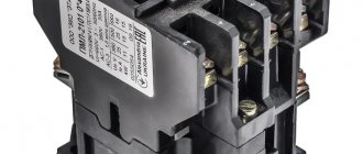
A magnetic starter is a device designed for switching power electrical circuits. The first thing you need to do before servicing or repairing a magnetic starter is to study the documentation for this starter, or, as they do in the 21st century, look it up on the Internet. It is also worth knowing the weak points of magnetic starters - contact groups. It is the contact groups that need careful examination. It is worth paying attention to the fastening elements and the body, which will be discussed in the article.
Contactors
The function of a magnetic contactor is to remotely control the switching on and off of power circuits in routine mode.
Modular contactor for DIN rail mounting
Principle of operation
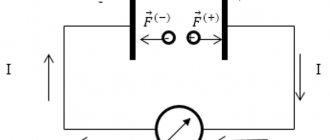
The electromagnetic device contains chokes with cores connected to closing contacts. The latter are responsible for the binary operation of closing and opening the current-carrying chain. The action diagram looks like this: when voltage is applied to the inductor, thanks to the emerging pulse, the moving component of the core moves towards the static one, and the circuit is closed. An electric current appears in it, and the equipment begins to work. When the supply of energy stops, the core is redirected by a spring to its original position. Then the circuit opens and the equipment turns off. The device coil receives power from the control circuit (no more than 230 V), and the closure of the contacts is related to the power circuit, which carries a large load.
Important! On the front panel of the device there are “Start” and “Stop” keys, through which you can initiate and stop its operation. When the contacts of the start key close, the same happens with the power ones, which remain in this position even when the button returns to its original state. This feature is due to the presence of additional contacts.
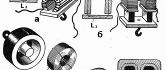
Device structure
Application area
These devices are used for switching reactive power circuits. One of the main areas of application is the coordination of the operation of powerful electric motors (more than 100 kW). They are also used in transport infrastructure. Modular devices are very popular.
Contact groups
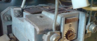
Basically, maintenance and repair of magnetic starters comes down to contact groups. To inspect them, you need to open the protective cover; the first thing we pay attention to is the contact groups. If there is slight carbon deposits, you need to clean it off with fine-grain sandpaper. As you can see in the photo, there is no oxidation. This means that the chosen method of protecting the starter from aggressive environmental factors is chosen correctly.
If traces of oxide, darkening, or rust are visible on the metal parts, then in this case it is necessary to definitely reconsider the method of installing the starter. Or rather, install it in a more dust- and moisture-proof shell. Then we inspect the contact groups for the presence of carbon deposits, deposits, and cavities. Depending on the degree of damage to the contact groups, a decision is made on repair or replacement.
Connection diagrams
What is a magnetic starter used for? Mainly for organizing the safe connection (and control) of asynchronous three-phase motors. Therefore, we will consider options for the operation of the circuit under various conditions. In all illustrations there is a protective relay indicated by the letter “P”. Bimetallic plates that activate the emergency switch (installed in the control circuit) are located on the power lines of the contact group. They can be placed on one or more phase conductors. If there is overheating (it occurs when the load is exceeded or a simple short circuit), the control line breaks and power is not supplied to the “KM” coil. Accordingly, the power contact groups “KM” open.
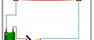
Classic circuit for direct connection of a three-phase electric motor
The control circuit uses power from the voltage between two adjacent phase lines. When you press the “Start” button, the “KM” coil circuit is closed using its main contact. In this case, all contact groups, including additional contacts in the control circuit, are connected under the control of the coil electromagnet. There are two ways to open the circuit: when the emergency relay is activated, or by pressing the “Stop” button. In this case, the magnetic starter returns to its original “all off” position (or in the case of two categories of contacts, the normally closed groups will be connected).
Purpose of the device
With the help of such devices the following is carried out:
- Turning on or off electric motors of mechanical drives in industrial equipment;
- Management of the external lighting system of populated areas and illumination of historical and industrial facilities;
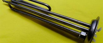
- When using electric heating, heating elements of heating devices are connected and disconnected;
- With their help, they switch electric motors and other starting elements in automation circuits;
- Switching devices are also widely used in household equipment.
Such devices are available for single-phase or three-phase starters.
Functional testing and maintenance
To do this, it is necessary to carry out an external inspection of the device. Pay attention to the condition of the coil. It should not have visible darkening or damage.
The contact group should not have any distortions, and the contacts should close simultaneously. Measure the activation and shutdown voltage of the device. The device should operate when the voltage gradually rises from 0 to 0.85 Unom. And turn off when the voltage drops to 0.45 Unom.
In order for the switching device to operate for a long time, it is necessary to carry out maintenance of the device during operation.
To do this, check the status of the connections. Clean the device from dust. Monitor the state of switching contacts. Inspect the metal parts of the device.
Pay special attention to the condition of the spring. It should be pretty tough. The turns are distributed evenly along the entire length. The anchor should not jam or warp.
If there are mechanical faults, lubricate or grind the parts. If the device is equipped with a thermal relay, its performance is checked on a special stand under laboratory conditions.
This test cannot be done at home. If a malfunction is detected, the device is repaired or replaced with a working one.
Device selection
As a rule, the choice of a magnetic starter is made at the equipment design stage. Sometimes the question arises of how to choose a magnetic starter during the repair process.
To do this, follow the following rules:
- First of all, technical characteristics and design features are considered;
- Select the device for the appropriate supply circuit voltage. In most cases this voltage is 220/380 volts. Less commonly, the switched network has a voltage of 380/660 volts;
- When choosing a device, consider the rated operating current of the switched mechanism. They are available for various switching currents from 6.3A to 250A;
- Then pay attention to the mechanical wear resistance parameter. It shows how many operation cycles the device can withstand without repair;
- The number of switching poles is taken into account;
- What voltage are the coils of magnetic starters designed for? They are available for supply voltages from 9 to 380 volts;
- Often contactors have auxiliary or additional contacts. They are used in automation and signaling circuits;
- The industry has mastered the production of special devices that can reverse switch engines. Such devices have two contactors in one housing;
- When choosing a magnetic starter, pay attention to the presence of a thermal protection relay.
When connecting the equipment yourself, the choice of starter is made according to the engine power.
There is a selection recommendation for this. According to which Inom is taken as the power of the electric motor multiplied by two.
Based on the obtained value, the motor is selected in such a way that the rated operating current of the three-phase motor is less than the current of the magnetic starter.
That is, the calculated data must be less than the values of the selected contactor. By default, the calculation assumes that the contactor is capable of withstanding inrush currents, which are many times higher than the operating currents.
So, to connect a 3.7 kW motor, the operating current will be 3.7 * 2 = 7.4 A. To connect an asynchronous motor of this power, it is enough to select a magnetic starter with an operating current of 10 A.
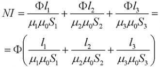
There are mathematical formulas for accurate selection of a device. Which allow you to accurately calculate the contactor parameters.
This formula is valid for selecting a device for 3-phase voltage. The coefficients η take the value 0.87, and cosφ= 0.88.
The contactor coil may fail due to:
- errors when selecting a contactor based on control voltage. Control voltage data is marked on the contactor housing (at the front for Eaton
and at the end for
Rade Koncar
).
- the coil voltage (control voltage) of the corresponding frequency must be in the range specified in the passport for a specific contactor.
Rade Koncar contactors
the range is 0.85...1.1Un and with a long-term voltage >1.1Un the coil is guaranteed to burn out. A solution may be to use stabilizing devices, as well as supply voltage control relays.
A short circuit in the control circuit can lead to overheating of the coil conductor and its failure.
It is necessary to use protection devices in control circuits: fuses (fuse links) or circuit breakers with ratings and characteristics equivalent to those of the coils. It is also necessary to monitor the quality of the control circuit insulation.
- A pulse overvoltage in the control circuit as a result of atmospheric phenomena (lightning strike) or due to switching overvoltages can break through the insulation of the coil. And then - interturn short circuit and destruction. The solution is to use surge protection devices SPDs, varistor modules, RC circuit modules and other surge protection devices.
Symptoms of device malfunction
Like all mechanisms, equipment failure occurs during operation. Malfunctions are characterized by the following symptoms:
- When turned on, you can hear a strong buzz from the starter. Which can lead to failure of the contactor coil. A normally operating device emits a barely audible hum;
- The main contacts are not switched on evenly. And as a result, the contacts burn out, and if a phase is lost, the electric motor may also fail;
- Reversible devices do not have reverse;
- The anchor sticks to the core;
- There is no self-locking.
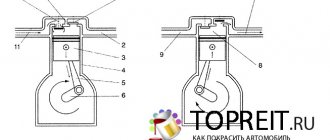
Structure and technical characteristics of magnetic starters
Almost all magnetic starters use three power poles (according to the number of phases), and also use an overload relay. To turn it on and off, there is a special lever (sometimes a button), which can be moved into two positions - on and off.
Inside the magnetic starter, as a rule, there is a coil of wire covered with a varnish insulating layer and two types of contacts: movable and fixed.
1 - base made of heat-resistant plastic, 2 - fixed part of the magnetic circuit, 3 - moving part of the magnetic circuit, 4 - electromagnetic control coil, 5 - contact clamps, 6 - metal platform (for starters rated over 25 A) 7 - traverse with moving contacts, 8 - mounting screw, 9 - return spring, 10 - aluminum rings, 11 - fixed contact, 12 - clip with a notch for fixing the conductors.
Also, in starters where the current can exceed 20A, additional three pairs of power contacts are provided, as well as several pairs of low-current contacts (the number of these contacts, depending on the structure of the starters, may vary). If you need to connect additional contacts to build complex circuits, you can additionally connect certain contact attachments.