Let's look at the types of manually operated mechanical switches, as well as their parameters and applications in electronic circuits.
What is a switch
Switches are elements that control the flow of electrical current in a circuit and play a key role where user interaction is required. These elements can only be in one of two states: open or closed. In the open (off) state, the switch is simply an open circuit. As a result, the circuit is broken, preventing current from flowing. When it is closed (on), the switch acts as a normal conductor (has resistance, inductance) through which electric current can flow and completes the circuit.
There are many types of switches: toggle switches, buttons, keys, keypads, membranes. Each type of switch has a set of unique features that set it apart from the others. Characteristic features include their mechanical parameters (switching method, number of controlled circuits) and electrical parameters (resistance, maximum permissible current, inductance, parasitic capacitance, and others).
Main advantages
Electric switch
It is impossible to distinguish the devices by appearance, but the operating principle is different. In some rooms it is inconvenient to use the switch (for example, in long corridors). The main advantages of switches are:
- the ability to connect several electrical networks to each other;
- the device allows you to control (turn on, switch, turn off) a branched electrical circuit from one point;
- one light source can be activated from different places in the room (for example, turn on the chandelier in the guest room from the corridor).
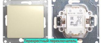
In fact, the device is constantly in working condition - this is one of the main differences between a switch and a switch. With the help of changeover contacts, additional electrical circuits are created in the network.
Switching method
To move from one switch state to another, some physical action must be performed that causes the physical state of the component to change. The way the switch is activated is one of its most distinctive features. The simplest distinction can be made at the boundary between switches that are activated by humans and switches that use other forces or phenomena to change their position. Activation of the switch can be done by sliding, pressing, pulling, rotating, or any other action, most commonly using your hand/fingers. But there are also foot-activated buttons on the market, or special elements activated, for example, by the elbow - even pressed with the tongue, designed for people with disabilities.
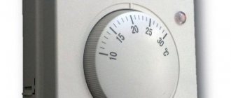
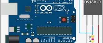
Switching elements that use physical phenomena other than human movement can be activated, for example, by temperature (thermostats), pressure (pressure switches), magnetic field (reed switches) and so on. They are most often used as safety or control elements in control systems. Although the mechanical characteristics of these types of components are completely different from human-activated switches, they are described by the same electrical parameters as other switches.
Areas of application
We can identify three main areas in which current and voltage switches are used:
- Residential buildings (private and multi-apartment).
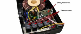
In urban condominiums, phase control relays are used in centralized power supply systems. In private homes, the devices allow you to control the operation of autonomous boiler rooms, video surveillance systems, security and alarm systems, and the functioning of local electrical energy supply networks. - Industrial and office buildings.
In this segment, switches are needed to create process automation systems. In general, for the operation of ventilation and climate control devices in general. As well as dispatch equipment, communications, remote control, industrial security and tracking systems. - Medical and related institutions.
We’ll talk about them separately, because a stable supply of current to them is sometimes literally a matter of life and death. Equipment that supports the vital functions of critically ill patients should not be turned off even for a minute. Some types of drugs and biomaterials should be stored in refrigerators, etc.
Let us separately mention the use of switches in Smart Home systems. Since in such houses all equipment is controlled centrally through computer programs, ensuring uninterrupted power supply can be said to be vital. Therefore, in such systems, the stable and safe operation of all devices and utility networks at home depends on the phase control relay.
Stable and unstable button
All switches fall into one of two categories: momentary (monostable) or fixed (bistable). A momentary (monostable) button is a switch that does not have a stable closing position (although there are also switches that are closed by default). This means that the circuit is completed only momentarily while the operator operates the switch in some way, then that switch returns to its default state. Most switches, called pushbuttons, are classified as momentary switches.
There are snap-on switches (stable) buttons, but they, in fact, represent a narrow group of these elements, therefore, when we usually talk about buttons, we mean a momentary button.
On the other hand, toggle switches behave the same way as light switches on the wall - they remain in one state until they switch to another, in which they then remain until the action is performed again.
Household use
Using a switch in stairwells
Installing or rewiring electrical wiring is all about functionality and ease of use. Therefore, before installation, a plan is drawn up, which specifies the total number of light bulbs, switches and sockets. Adapter devices are suitable for connection in the following situations:
- multi-level buildings - switches will allow you to turn off the lights on any floor;
- long corridors - you can turn on the lamps at the beginning and turn them off at the end;
- bedrooms - if you install one mechanism at the entrance, and the second near the bed, you will not need to get up to turn off the main light.
Use transition devices in all similar situations. This is especially true in large offices, hotels and other similar buildings.
Switch poles and positions
The switch must have at least two contacts - one acts as a normal input, the other as a normal output, but this only applies to the simplest version of the switch. Most often the switch has more than two contacts. There are generally many different switch configurations, which are described by the number of circuits and the position.
- The number of poles in a switch determines the number of individual circuits it can control. A single-pole switch can control only one circuit, but a four-pole switch can control four different circuits at the same time.
- The number of switch positions determines how many contacts each pole of the switch can be connected to. For example, if a switch has two positions, each circuit (pole) in the switch may be connected to one of the two contacts.
Knowing how many poles and positions a switch has, you can more accurately classify it and present its circuit diagram (and vice versa). Typically switches fall into one of the following categories:
- single-pole single-circuit - SPST ,
- single-pole double-circuit - SPDT ,
- two-pole double-circuit - DPDT .
Of course, there are switches with a large number of poles and switched circuits.
How the device works
How does this mechanism work? First of all, the operator uses the handle to start the mechanism of the moving washers. They transfer their movement to the contact group area. As a result of this, rapid opening and closing of the conductor contacts is observed, depending on the selected mode of the batch switch.
This device has two handle positions that help you turn the device on and off. If you move suddenly, a sharp surge in electricity may occur, which will cause the contacts to burn out. If the mechanism has a cam switch, then it can be “programmed” to switch the contact group as required.
The device is used on lines with low AC voltage up to 360 W and DC up to 220 W. The operating state of the switch is 60Hz. These devices do not provide effective protection. The low cost of the device makes it popular among potential consumers.
Modern models have switch poles and directions. They are responsible for turning on a certain number of communication packages, each of which is equipped with stationary and moving contacts. The stationary type of contacts is made in the form of knives and is fixed in a plastic case with washers.
The moving contacts are fixed in insulated rotary pins. When viewed externally, the device has an oval shape with additional connectors for fixing the conductors. There are additional latches on the surface of the cover that help set the desired mode of the device.
SPST switches
A single-pole, single-circuit SPST switch has one input and one output, and can be closed or open by default. It is used as switches or momentary buttons on a keyboard. The SPST rocker switch and its circuit diagram are shown in the figure below.
Change-over switch for generator
The switch for the generator must be a single-module modification, and the interlocking design must have a classic contact pattern. Speaking of the reversing unit, it is manufactured in a version with a controller. As a result, on devices equipped with a resonator, there is no need to set the selection.
Before you start installing a switch, you need to carefully study how the grounding system works. It must contain a special grounding electrode with markings containing all the necessary information about protection.
Most often you can find products on sale labeled “IP30”. Such information suggests that the consumable has fairly reliable insulation.
SPDT switches
Another common type of switch is the SPDT, which is a single pole element with two circuits. It has three contacts: one common and two, between which the signal from the common contact is switched. SPDT is ideal for choosing between, for example, two power supplies or two signal sources. It allows you to easily connect one of two circuits to a common element.
The simplest SPDTs are designed as slide switches. The figure shows an example of a slide switch with a schematic diagram of this element.
Device design
This design received its name due to its structure. Identical parts of communication elements are assembled on one long axis. The photo of the packet switch shows the detailed structure of this installation.
The housing is made of high-quality insulating material. There are additional holes on the surface for electrical contacts. There are arc suppression chambers here. In the center there is a movable washer, which is also made of high-quality insulation. It has legs made of electrodes. These several elements, which are located on the long axis, help to activate the mechanism.
DPDT Switches
Double Pole Double Circuit Switch - DPDT is similar to two SPDT switches that can control two separate circuits but are mechanically linked to each other and switch together. The DPDT switch has six contacts. The figure shows a rocker switch with this design and its circuit diagram.
DPDT switches are ideal for switching, for example, balanced signals or any other where it is necessary to switch two lines at once. In addition, such switches are often used to disconnect power from 220 V devices - both lines are turned off simultaneously (phase and neutral wires), since it is usually unknown which line the phase is on.
Types of switches
There are two main types of changeover switches:
Single-pole. The most common type. As can be seen in the photo of a single-pole changeover switch, its design is equipped with one module. For this variation, copper conductors are used. This is the optimal choice for generators with a frequency not exceeding 20Hz.
Bipolar. The most popular type today. Its area of application is residential buildings. A two-input switch allows you to service devices connected not only to a single-phase, but also to a three-phase power supply. Such devices have a negative resistance of 60 Ohms. Moreover, the output voltage can be very different. It depends on the version of the device used.
Today, most often in stores you can see PP20 switches equipped with open capacitors. When connecting such devices, it is necessary to use 300V power supplies.
Multi-pole switches
High pole count switches are not very common, but are available in many amazing configurations. They are described similarly to single-pole or double-pole switches/circuit switches, with the first letter (S or D) replaced by a numerical designation. This is how you can imagine, for example, a 4PDT switch that can control four separate circuits with two positions per circuit. An example of such a switch along with the circuit is shown in the figure below.
The situation is similar with switches with a large number of positions. If a four-way switch can be set to one of four positions, for example, it will be designated 4P4T. What will the SP12T switch look like? This could be a rotary switch (bar type), which has 1 pole and 12 positions.
Popular brands
Voltage switches
– the devices are not the most complex and widely used. They are produced by many Russian and foreign manufacturers. Here are the most famous brands.
- DigiTop .
The brand belongs to the Ukrainian company, created in 2007. The company specializes in the production of low-voltage equipment. Production is established in the country of the brand, and supplies are in Russia, Kazakhstan, Eastern European countries, even Turkey. - ABB .
The company is the result of a merger in 1988 between Swiss and Swedish electrical manufacturers. 40% of production capacity is located in Germany. The products meet the quality requirements of the European Union and are certified according to ISO:9001.
Of course, these are not all companies producing phase control relays. More information about brands and brands can be found in our “Manufacturers” section.
Installation and mechanical parameters
The switch can be integrated into the circuit in different ways. The main division in this regard is between panel-mounted and PCB-mounted elements. This is not a strict classification, as there are many switches soldered to printed circuit boards, but intended for panel applications.
Like most electronic components, they can be classified into surface mount components (SMD) or through-hole mount components (THT). Elements for through-hole assembly are usually larger, THT allows higher mechanical loads to be transferred. SMD switches are smaller than their THT counterparts, typically much lower in height, take up less PCB space, and require little force to switch.
Panel-mounted switches are equipped with elements that allow them to be mounted in a housing. They usually have threaded bodies that allow them to be tightened with a nut, but manufacturers also use other solutions. Pins are adapted for THT, SMD or cable assembly.
Purpose
A cam switch is needed for:
- control of mechanisms that are driven by three-phase and single-phase motors, to change the connection of the windings of alternating current motors (star-delta), change the direction of rotation;
- control and signaling in operational circuits;
- can work as a switch, switch for operating positions of an electric welding machine;
- switching the required connection of the resistance group;
- ensuring switching of operating modes of heating equipment;
- turning on and off the drive of the sectional disconnector mechanism in transformer substations.
Environmental resistance
Panel switches are often exposed to the elements. The main threats to these elements are dust and moisture. The IP rating assigned to a switch indicates its resistance to these factors. The degree of protection and IP classes are defined in the IEC 60529 standard.
The IP class is described by two numbers, written in the IPxy format, where x is the first characteristic digit, indicating protection against access to the inside of the housing, as well as protection against dust penetration inside. And y is the second characteristic digit indicating the waterproofness of the switch.
The lowest protection class, IP00, means a device without access protection, in this case a button. The protection class indicates, for example, the size of bodies that can get inside the button, or protection against dust. In the case of protection against ingress of water, the levels of protection vary from droplets of water (level 1) to protection against flooding by a powerful jet of pressurized water (100 bar at 80°C). in accordance with DIN 40050 (class 9). The highest protection class is IP69.
Just as the IP class determines resistance to dust and moisture, the IK class determines the resistance of elements to mechanical damage, the so-called vandal resistance. The IEC 62262 standard defines the mechanical resistance of elements as the amount of mechanical shock energy that a given element can withstand without damage. The standard also specifies the height from which an element can fall without damage or other mechanical testing. The division is divided into classes from IK00 - the element is not at all resistant to mechanical damage, to IK10, where the element can withstand an impact with an energy of up to 20 J (a steel ball weighing 5 kg and with a radius of 50 mm, falling from a height of 40 cm).
Design
From the very name of this device it is clear that the design is due to the use of “cams”, which drive a kind of “pusher”. The design of a cam switch assumes the presence of a group of switching elements, by changing the position of which it is possible to achieve a certain arrangement for the operation of different switching circuits. The arrangement of contacts and cams is called a switching program (its purpose is to assemble a specific connection diagram). They are located inside a plastic case, which is made on the basis of melamine.
You can clearly see the design of the device in the diagrams below:
Such a housing is immune to electric arcs and eddy currents. The design of the cam switch makes it possible to turn all contacts on and off almost simultaneously. This is ensured by the fact that the cam of one element is mechanically connected to other cams. The use of silver in the contact device, which can withstand an electric arc better than copper, provides good switching characteristics and increased wear resistance. The switch must be clearly fixed in a certain position, for which a drive locking mechanism is needed. The design also includes a drive motion limiter. Its purpose is to clearly set the switch in the extreme position. The drive or shaft of the apparatus is a square rod. For reliable operation and good contact switching, it must be made of metal to withstand the load of cranking
This is very important where motor control is used. To control the switch drive, a handle made of insulating material is used
The design of the cam switch is clearly demonstrated in the video from one of the best manufacturers of sockets and switches, ABB:
Electrical parameters of switches
The main electrical parameters of switches are the rated voltage and current, contact resistance and the maximum permissible number of switch movements (switching operations).
- Rated voltage is the maximum voltage that the switch can withstand. This is determined by many factors, including insulating materials, open contact distance, disconnection speed, and safety considerations.
- Forward current rating is the maximum direct current (or alternating current) that a switch can pass through its closed contacts. This current is limited mainly by heating of the switch due to loss of contact resistance.
- Contact resistance is the electrical resistance through which current flows in a closed switch. Because the switch contacts are not a continuous conductor, the contact resistance is greater than that of a comparable continuous conductor. This may cause voltage drops, especially at higher currents.
- The number of operations is the estimated maximum number of switch closures after which electrical and other parameters may deteriorate. Since the switch is a mechanical element, each movement of the switch causes a certain degree of wear on the mechanisms within the element, which leads to deterioration of the switch's performance.
Recommendations for selection
When choosing a phase switch, it is important to understand where it will be installed and what it is needed for. For example, a manual relay requires regular human supervision and is unlikely to be convenient for home use. At the same time, powerful and high-precision automatic and, especially, high-cost electronic models are intended for production, and are clearly redundant for household networks. When choosing, the key factors are the following technical parameters:
- Maximum permissible current.
This refers to the maximum current at which the relay can perform phase control. Typical values are 40, 60 or 80 amperes. Typically, these values are indicated on the front panel of the device. If they are exceeded, the relay breaks down. - Possibility of adjustment.
In the simplest models it is absent. For reliable operation, you should set at least the permissible voltage range, beyond which you need to change the wire. It’s also a good idea to set a time for returning to the main phase. - Data display method.
Namely, the active phase, the current voltage and the degree of criticality of the main phase failure. Simple models use LED indication (one diode per phase), while more advanced ones use LCD displays, which reflect all settings. - Functional settings.
Basic preset settings are suitable for most devices. But some may require special settings. It is important that the switch allows the user to set the required voltage and other parameters.
For home electrical networks, a simple automatic two-phase model of 220 volts, not necessarily with electronic filling, will be sufficient. But a three-phase automatic or (less often) manual phase switch is needed to ensure safe uninterrupted power supply in medical centers, industrial production, etc. At the same time, the brand is not of fundamental importance - a wide range of devices is produced under each brand.
Keyboards
A keyboard is a matrix of buttons that is most often used to enter data into a device. A common example is the alphanumeric computer keyboard, which, along with a mouse, is used to control the PC. There are many types of keyboards and many technologies used to produce buttons for them. One of the most common types of keyboards is the membrane keyboard.
It consists of thin dielectric and conductive layers glued together. Pressing the field causes the two layers to shorten and join together, thereby completing the button circuit. These types of keyboards, in addition to being compact, are notable for their low price. But this is due to reduced user comfort - a small stroke and, as a rule, the absence of tactile communication worsen the comfort of use. On the other hand, mechanical keyboards that provide noticeable travel provide much greater comfort, but are more expensive and more difficult to manufacture.
Keyboards can be found on many devices, especially those that require data input. The most common are digital keypads, which can be found in electronic locks, intercoms or ATMs. The latter often install keyboards with increased resistance to damage, the so-called anti-vandal protection.
Connection diagram
After purchasing, you may have difficulty with how to connect the phase switch. If you do not have experience working with electricity, it is better not to try, since you will have to work with high voltage in a three-phase network - 380 Volts. In addition, improper use and connection of such equipment can lead to a short circuit between phases.
The phase switch is a modular device that is installed in a panel on site on a DIN rail. A three-phase circuit breaker is installed in front of it. After installing the primary circuit, we move on to the output circuit. But how to connect the secondary circuits depends on the switch model. The connection diagram must be indicated in the technical data sheet or other similar documentation and may differ from manufacturer to manufacturer.
Finally, we recommend watching a video that explains in more detail what a phase switch is and how to connect it in the panel:
A phase switch is a low-cost method that will increase the stability of the power supply; this can be especially important outside the city in a cottage or holiday village, where there are usually power outages. We talked about how to connect and where to install, as well as all the parameters of such devices. The choice of uninterrupted supply is yours based on your needs and budget.
It will be useful to read:
Lighting with cross switch in TN-S network
Connecting a crossover switch in a TN-S power network, which is characterized by the separation of the working (N) and protective (PE) zero, has some nuances. Unlike the old, not entirely safe TN-C system, the electrical network conducted according to the new standards uses 3 wires when supplying single-phase voltage, and 5 when supplying three-phase voltage.
The wire that performs the function of zero (N, marked in blue) comes out of the electrical panel, passes through the branch box and is connected to the zero of the lamp. The ground wire (PE, indicated in yellow-green color) is connected to the ground wire of the lighting fixture.
Laying electrical networks using the TN-S system significantly increases the cost of materials, but reduces the risks associated with the operation of electrical equipment