We continue our section on electronic homemade products; in this article we will consider devices that support a certain thermal regime, or signal when the desired temperature has been reached. Such devices have a very wide scope of application: they can maintain a given temperature in incubators and aquariums, heated floors, and even be part of a smart home. For you, we have provided instructions on how to make a thermostat with your own hands and at a minimum cost.
Purpose of thermostats
Any electric or gas boiler is equipped with an automation kit that monitors the heating of the coolant at the outlet of the unit and turns off the main burner when the set temperature is reached. Solid fuel boilers are also equipped with similar means. They allow you to maintain the water temperature within certain limits, but nothing more.
In this case, the climatic conditions indoors or outdoors are not taken into account. This is not very convenient; the homeowner has to constantly select the appropriate operating mode for the boiler on his own. The weather can change during the day, then the rooms become hot or cool. It would be much more convenient if the boiler automation was oriented towards the air temperature in the rooms.
To control the operation of boilers depending on the actual temperature, various heating thermostats are used. Being connected to the boiler electronics, such a relay turns off and starts heating, maintaining the required temperature of the air, not the coolant.
Concept of temperature controllers
Products in this category are used to solve various problems. Based on the appropriate temperature threshold setting, power is supplied (turned off):
- heating in the cellar;
- heating the soldering station;
- boiler circulation pump.
From the examples given, the basic requirements for accuracy that a suitable thermostat circuit must provide are clear. In some situations it is necessary to maintain a given level no lower than ±1C°. To monitor operating parameters, an operational indication is needed. Load capacity is essential.
The listed features explain the purpose of typical functional units:
- the temperature value is recorded with a specialized sensor (resistor, thermocouple);
- the readings are analyzed by a microcontroller or other device;
- the actuator signal is sent to an electronic (mechanical) switch.
For your information. In addition to the parts discussed, the thermal relay circuit may contain additional components to supply power to an electric heater or other powerful load.
Types of thermal relays
A conventional thermostat is a small electronic unit installed on the wall in a suitable location and connected to a heat source by wires. There is only a temperature regulator on the front panel; this is the cheapest type of device.
In addition to it, there are other types of thermal relays:
- programmable: they have a liquid crystal display, are connected using wires or use wireless communication with the boiler. The program allows you to set temperature changes at certain times of the day and by day during the week;
- the same device, only equipped with a GSM module;
- autonomous regulator powered by its own battery;
- wireless thermal relay with a remote sensor to control the heating process depending on the ambient temperature.
Note. A model where the sensor is located outside the building provides weather-dependent control of the operation of the boiler installation. The method is considered the most effective, since the heat source responds to changing weather conditions even before they affect the temperature inside the building.
Multifunctional thermal relays that can be programmed significantly save energy. During those hours of the day when no one is home, there is no point in maintaining a high temperature in the rooms. Knowing his family's work schedule, the homeowner can always program the temperature switch so that at certain times the air temperature drops and the heating turns on an hour before people arrive.
Household thermostats equipped with a GSM module are capable of providing remote control of the boiler installation via cellular communications. A budget option is sending notifications and commands in the form of SMS messages from a mobile phone. Advanced versions of devices have their own applications installed on a smartphone.
Communities › Kulibin Club › Blog › Electrics: Temperature sensors, we make it ourselves.
Sometimes there is a need for temperature control of some process, be it a car or a national economy. There are many different thermal control schemes, but the sensors usually have an inconvenient design that does not allow for mounting in a controlled environment. Let's talk about sensors.
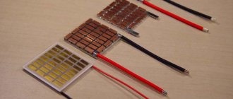
As a rule, semiconductor devices - thermistors - serve as sensors for measuring circuits:
The case may be different, but inside there will still be about the same droplet with leads.
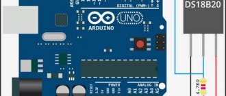
The second common temperature sensor is the DS1820:
They are often sold as follows:
Inside is the same DS18B20 microcircuit with three pins, even without thermal paste.
Now let's try to implement these radio components into a car, for example, for digital display of coolant temperature or control of electric fans.
We will need a donor sensor - any suitable thread and cost. In my case, this is the Volga-UAZ sensor TM 106-10
:
We take a drill as a lathe and carefully clamp the sensor into the chuck. Using a metal hacksaw, we cut off the rolling. When the sensor falls apart into its component parts, use a drill to even out the edge of the sensor with a file. We receive a blank housing for introducing our radio component there.
Then you can go in two ways: 1. Pour molten solder into the body, drill a channel in this solder and insert a thermistor there. You can fill the housing cavity with thermal paste and stick the thermistor into it, but tin’s thermal conductivity is several orders of magnitude better than thermal paste, so thermal paste must of course be used, but it’s better to apply a thin layer of it.
The disadvantage of this method is the high inertia of the resulting sensor.
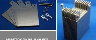
2. Do it the way I do it. Take a telescopic antenna from some old unnecessary device:
If you threw them away before, you did it in vain, because such antennas are a source of wonderful thin-walled brass tubes of different diameters:
We select the tube most suitable for the thermistor - it should be inserted as tightly as possible into the tube. We measure and again use the drill, cut off the piece of tube we need - it’s better to cut with a needle file. We take our blank body and drill its end according to the diameter of the tube. We tin the end of the body with tin, strip the tube down to brass and also tin it. We insert the tube into the case and solder them to each other, an 80W soldering iron is enough for your eyes. It should look something like this (the end is already sealed with a small piece of copper foil 1mm thick):
We check the resulting sensor housing for leaks. I do it not very technologically - using tongue suction
If everything is in order with the tightness, we proceed to the next stage: installing the thermistor and connector.
Again, we try everything on and cut off the leads of the thermistor so that when installed in the housing, the thermistor is at the end of the tube, or better yet, rests against the end:
The thermistor is now ready for installation. We put a little thermal paste inside the tube, coat the thermistor itself with a little thermal paste and insert it into the tube. After the thermistor has entered the tube under the connector, we place a little pre-prepared poxypol or epoxy plasticine. We press the connector into the polyester and remove the excess. When the Poxypol has completely hardened, you get this nice sensor ready for installation:
And this is how the sensor will stand at its workplace - the measuring part will be completely washed by the working environment:
Well, here’s a picture of a general check of the functionality of the electrical part:
How to assemble a thermal relay yourself?
Heating control devices available for sale are quite reliable and do not cause any complaints. But at the same time, they cost money, and this does not suit those homeowners who have at least a little knowledge of electrical engineering or electronics. After all, understanding how such a thermal relay should function, you can assemble and connect it to the heat generator with your own hands.
Of course, not everyone can make a complex programmable device. In addition, to assemble such a model, it is necessary to purchase components, the same microcontroller, digital display and other parts. If you are new to this matter and have a superficial understanding of the issue, then you should start with some simple circuit, assemble it and put it into operation. Having achieved a positive result, you can move on to something more serious.
First, you need to have an idea of what elements a thermostat with temperature control should consist of. The answer to the question is given by the circuit diagram presented above, which reflects the operating algorithm of the device. According to the diagram, any thermostat must have an element that measures temperature and sends an electrical impulse to the processing unit. The latter’s task is to amplify or convert this signal in such a way that it serves as a command to the actuator - the relay. Next we will present 2 simple circuits and explain their operation in accordance with this algorithm, without resorting to specific terms.
Principle of operation
The principle on which all regulators work is the removal of a physical quantity (temperature), transmission of data to the control unit circuit, which decides what needs to be done in a particular case.
If you are making a thermal relay, the simplest option will be to have a mechanical control circuit. Here, using a resistor, a certain threshold is set, upon reaching which a signal will be given to the actuator.
To get additional functionality and the ability to work with a wider temperature range, you will have to integrate a controller. This will also help increase the service life of the device.
In this video you can see how to make your own thermostat for electric heating:
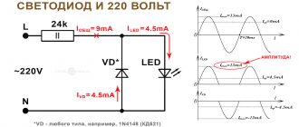
Circuit with zener diode
A zener diode is the same semiconductor diode that passes current only in one direction. The difference from a diode is that the zener diode has a control contact. As long as the set voltage is supplied to it, the element is open and current flows through the circuit. When its value falls below the limit, the chain breaks. The first option is a thermal relay circuit, where the zener diode plays the role of a logical control unit:
As you can see, the diagram is divided into two parts. On the left side is the part preceding the relay control contacts (designation K1). Here the measuring unit is a thermal resistor (R4), its resistance decreases with increasing ambient temperature. The manual temperature controller is a variable resistor R1, the power supply to the circuit is 12 V. In normal mode, a voltage of more than 2.5 V is present at the control contact of the zener diode, the circuit is closed, the relay is turned on.
Advice. Any inexpensive commercially available device can serve as a 12 V power supply. Relay – reed switch brand RES55A or RES47, thermal resistor – KMT, MMT or similar.
As soon as the temperature rises above the set limit, the resistance of R4 will drop, the voltage will become less than 2.5 V, and the zener diode will break the circuit. Then the relay will do the same, turning off the power part, whose diagram is shown on the right. Here, a simple thermal relay for the boiler is equipped with a triac D2, which, together with the closing contacts of the relay, serves as an executive unit. The boiler supply voltage of 220 V passes through it.
Tags: temperature sensor, sensor manufacturing
Comments 153
I installed exactly the same one on a double-circuit boiler. The third season is already plowing. The power supply is from an antenna amplifier. Did you have a controller with a sensor?
no, as far as I remember, I bought the sensor separately at Chip and Deep
But in general, then I assembled everything I had planned on the DS18B20
And this option: a thermocouple attached to the pipe and a simple multimeter in temperature measurement mode
Tell me, what kind of display board is it? Homemade?
no, not homemade - a friend bought a “bunch for a heel” on Aliexpress and gave one to me:
Have you ever thought of stirring up such a thing yourself?
Thought. On the DS1820 sensor. But it so happened that I went to visit a friend, we started talking over a glass of tea, I told him what I wanted to do, and he took this device from the shelf and gave it to me. Now the need for independent production seems to have disappeared. But I’ve already done it according to this scheme before and I have everything for it:
Dallas works better compared to thermistors, and digitally. However, the range is small.
why is it too small? More than enough for use in cars.
Dallas, in principle, has a better measurement range. But the upper limit is critical. The thermistor, as far as I remember, is not reliable. Although if the potential sits at 12 volts, it works. But Dallas needs stable power.
Can you tell me more about what the top bar is critical? I heated the sensor to more than 120 degrees with a hairdryer, it seemed to work after that.
The upper temperature range seems to be 125 degrees in Dallas. That is, -50 and +125. And if you need a controlled temperature above 125, then Dallas will not cope. In general, its accuracy is normal, but there is a delay of 0.5-1 seconds. There is a 3-wire connection, it is possible to connect via 2 wires. There will be a delay and the range will be less.
I know about these connections, just for fun I tried to heat the sensor with a hairdryer, I was able to see 127.9 as much as possible on it, beyond zero, when it cools down it returns to normal)
no, this is already a proven technology. I only got confused by taking pictures of everything, formulating it and posting it here)
I understand that it’s used, but is it really worth the effort given the relatively low cost of the sensor? Although of course there are rare and expensive sensors...
no, it’s not a matter of cost, it’s a matter of fitting a Chinese sensor into the required structure. You need to regulate the temperature of the water, for example, with a boiler - you just can’t put the sensor in the water; you have to screw it in somehow, so you need a housing.
By the way, what a cool idea...listen, how much would the cheapest sensor like this cost? If only it would open the circuit like a thermostat and then there would be no price...
I understand that it’s used, but is it really worth the effort given the relatively low cost of the sensor? Although of course there are rare and expensive sensors...
Well, look - I, for example, have a Bosch Mono-Jetronic, according to all the tables, DTVV and DTOZH should (at the same air temperature and coolant) give the “brains” the same resistance. At the same time, the DTVV is quite adequate, but cannot be replaced (due to design features). And the DTOZH is “buggy”; when the readings differ, the ECU begins to “adjust”, because can’t figure out who to believe (DTOZH or DTVV)! I bought 4 (FOUR) different sensors - they all give different resistance at the same temperature! And with the technology described above, it is possible to select a cheap thermistor for almost any resistance value at a given temperature! Yes, whatever, you can replace BOTH thermistors (by selecting the required resistance) with both DTOZH and DTVV! And this will help solve several problems with “glitches” of the electronic power system at once! Moreover, the price of Chinese thermistors, consumables, etc. There is no comparison with “branded” sensors (which sometimes cannot be replaced, or they cost like an airplane wing)! Am I explaining this clearly? )))
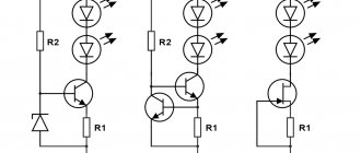
Circuit with logic chip
This circuit differs from the previous one in that instead of a zener diode, it uses a K561LA7 logic chip. The temperature sensor is still a thermistor (designation VDR1), only now the decision to close the circuit is made by the logical block of the microcircuit. By the way, the K561LA7 brand has been produced since Soviet times and costs mere pennies.
For intermediate amplification of pulses, the KT315 transistor is used; for the same purpose, a second transistor, KT815, is installed in the final stage. This diagram corresponds to the left side of the previous one; the power unit is not shown here. As you might guess, it may be similar - with the KU208G triac. The operation of such a homemade thermal relay has been tested on boilers ARISTON, BAXI, Don.
Required materials and tools
In some situations, you will need the skills to make a complex printed circuit board. The simplest circuits are assembled in a few minutes using a soldering iron and surface-mounting technology. Before performing work operations, you must purchase:
- components;
- Consumables;
- measuring equipment.
The shopping list is compiled based on the selected electrical circuit. To protect the device from adverse external influences and improve its appearance, an appropriate housing is created.
Assembly instructions
Required materials, parts and tools:
- magnifying glass;
- pliers;
- soldering iron;
- insulating tape;
- several screwdrivers;
- copper wires;
- semiconductors;
- standard red LEDs;
- pay;
- forged textolite;
- lamps;
- Zener diode;
- thermistor;
- thyristor.
- display and internal generator with a capacity of 4 MGU (for creating digital devices on a microcontroller);
Step-by-step instruction:
- First of all, you need an appropriate microcircuit, for example, K561LA7, CD4011
- The board must be prepared for laying tracks.
- Thermistors with a power of 1 kOm to 15 kOm are well suited for such circuits, and it must be located inside the object itself.
- The heating device must be included in the resistor circuit, due to the fact that the change in power, which directly depends on the decrease in degrees, affects the transistors.
- Subsequently, such a mechanism will warm the system until the power inside the temperature sensor returns to its original value.
- Regulator sensors of this type require adjustment. During significant changes in the surrounding atmosphere, it is necessary to control the heating inside the object.
Assembling a digital device:
- The microcontroller should be connected together with the temperature sensor. It must have the output ports that are required to install standard LEDs that work in conjunction with the generator.
- After connecting the device to a network with a voltage of 220V, the LEDs will automatically turn on. This will indicate that the device is in working condition.
- The microcontroller design contains memory. If the device settings are lost, the memory automatically returns them to the originally specified parameters.
When assembling the structure, we must not forget about safety precautions. When using a temperature sensor in a watery or humid atmosphere, its terminals must be hermetically sealed. The value of thermistor R5 can be indicated from 10 to 51 kOhm. In this case, the resistance of resistor R5 must have a similar value.
Instead of the designated K140UD6 microcircuits, you can use K140UD7, K140UD8, K140UD12, K153UD2. Any instrument with a stabilization power of 11…13 V can be used as a zener diode VD1.
In the case when the heater exceeds the voltage of 100 W, then the VD3-VD6 diodes must be superior in power (for example, KD246 or their analogues, with a reverse power of at least 400V), and the thyristor must be mounted on small radiators.
The value of FU1 should also be made larger. Controlling the device comes down to selecting resistors R2, R6 in order to safely close and open the SCR.
↑ 5. Some features
During operation, the heater-regulator works “like an iron.” If the LED is on, heating is in progress; if the LED is off, the desired temperature has been reached. But there are some peculiarities here. Since there is no forced mixing of water, the temperature in the tank is distributed unevenly. Let's take the first cycle. Heating is in progress. When the water near the thermistor and it itself warm up to the desired temperature, the water near the heating element will already heat up much more. The average temperature will be increased and heating will be uneven. But after several heating-cooling cycles, the average temperature will be close to the set one. To minimize the deviation of the average temperature in the tank from the set one, one should search for the optimal relative position of the heater and sensor in the tank.
I consider the best solution for a country shower to be a system of two tanks with hot and cold water and a standard mixer. Hot water heats up to 60...70 degrees. The mixer will allow you to get any temperature, but I was given a different task.
What to consider when choosing a device
There are a large number of devices on the market, the functionality of which varies markedly, which directly affects its cost. When purchasing universal current clamps, you must take into account that this is still a specialized tool for determining the current strength in a live conductor. Therefore, it is worth deciding for yourself whether this device needs such functions, for example, as checking capacitors, diodes and transistors.
A regular multimeter can do everything the same, only its dimensions and weight are much smaller, but in any case this is a matter of taste.
The main tasks that the device must perform:
- Measurement of current and voltage (ideally AC and DC).
- Testing wires (preferably with a sound signal)
- Determination of current frequency.
Desirable options that in some cases make work easier:
- Fixing measurement results – “Hold” button
- Possibility of setting zero - if neighboring wires give interference.
- Possibility of measuring inrush current, which is several times higher than the rated current.
- Automatic range selection when displaying results.
- A plus will be the ability to connect a temperature probe to measure temperature.
- Large backlit display.
It is also imperative to pay attention to the quality of the plastic, the absence of metal parts on the surface of the device, and what batteries are used (so that they can be easily found and replaced, if necessary)
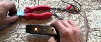
Visually about current clamps in the video:
As a result, a current clamp is a device that greatly simplifies the work of a professional electrician and a home craftsman who is used to doing everything with his own hands. Using the device, in general, is no different from taking measurements with a tester or multimeter - it is intuitive and accessible even to people with minimal skills, but in some cases some knowledge will be needed to interpret the obtained measurement results.
Switching on the load
An automotive relay can be used as an actuator that supplies power to the heater. It is designed for a voltage of 12 V, while a current of 100 mA must flow through the coil.
Let us remember that the current in the temperature sensor circuit does not exceed 5 mA, so to connect the relay you need to use a transistor with higher power, for example, KT814.
You can use a relay with a lower turn-on current, such as SRA-12VDC-L or SRD-12VDC-SL-C - then a transistor will not be needed.
↑ 1. Technical specifications
Since the customer could not clearly say what he needed, he had to come up with it himself. Adjustment range.
I determined a comfortable water temperature when I got under the shower with an alcohol thermometer. The range, with some margin, turned out to be +30...40 degrees.
Heater power.
I chose the power of the heating element 1 kW for the following reasons: conventional electrical fittings (contacts, wires, etc.) are designed for 6 A. We must take into account the limitation of power consumption in the country. Then, we must take into account that the water should not be boiled, not turned into steam, which takes the lion’s share of the power, but simply heated. Choosing, for example, a heater with a power of 2 kW or more would lead to the fact that the installation would have to be done with thick rigid wires rated for a current of 10 A. In addition, a larger heat sink would be required, and I wanted to make a small-sized device.
Electrical safety.
Good grounding is not so easy to do. And the only reliable protection when using a shower can only be to completely disconnect the heater from the power supply. Based on this, the design was chosen - before taking a shower, the device must be unplugged from the socket. An additional degree of protection is a power switch with disconnection of both wires. In addition, there must be complete galvanic isolation of the temperature sensor and the control board from the network. It is clear that we cannot guarantee the insulation of the heating element; however, all measures must be taken to reduce the possibility of electric shock even in the event of gross violations of safety precautions by the user. Here you need to turn on the RCD, but this is beyond the scope of our topic.
Important nuances
It is not necessary to use the K140UD6 microcircuit. It is allowed to use analogs of D2, D7, D8, D12. The recommended zener diode can be replaced by any other. The main thing is that the power is between 11 and 13 V.
FU1 should also be more important. To ensure safe opening and closing of the SCR, resistors R2 and R6 are selected.
These elements are used to control the device. The thermistor R5 can have a designation in the range of 10-51 kOhm, and the resistance of the resistor can be similar.
It is imperative to follow safety precautions. The terminals of thermostats that are designed to operate in a humid or watery environment must be hermetically sealed.