Physically designing and testing circuits is a difficult and difficult task, but with the help of these programs, we will be able to test our designs first before implementing them to ensure that everything works the way we want, thus avoiding any type of failures and costs. overspending. ,
Contents [show]
- Free KiCad programs
- ProfiCAD
- Free PCB
- TinyCAD
- What
- printed circuit board
- Folk instruments Multisim
- EasyEDA
Free programs
Not because they are free, they don't have to be bad or provide fewer features than paid programs. This is particularly sufficient for any specialist who does not want to pay for the use of software for designing and testing electronic circuits.
KiCad
KiCad is a free cross-platform tool for creating electronic circuits and PCB layouts. It has a project manager, schematic and component editor, fingerprint selector, PCB editor, Gerber file viewer, component or fingerprint creator from bitmaps, PCB calculator and page format editor.
ProfiCAD
ProfiCAD is a free cross-platform tool for drawing electrical and control circuit diagrams, although it can also be used for hydraulic, pneumatic diagrams and other types of technical diagrams. Its interface is very simple and includes many symbols, although it also allows you to create your own designs (paid features). Supports automatic numbering of symbols, cable lists, materials and other advanced functions.
It is translated into many languages and the non-commercial edition has limitations that do not support features such as bill of materials, netlist, cable list, modular coordinates, block header editor and some other limitations.
Free PCB
Free multi-platform tool Free PCB is an easy-to-use PCB editor, but does not have automatic net tracking. It allows you to create up to 16 copper layers, design circuits with a maximum size of 152 square centimeters, has many pre-designed elements and allows you to import/export PADS-PCB, Gerber and Excellon lists.
TinyCAD
TinyCAD has several symbol libraries and also allows you to create network lists that can later be used in PCB design programs such as FreePCB.
What
Cooks is a multi-platform GUI program based on Qt capable of simulating the signal and noise of small and large microwave circuits. This allows you to perform pure digital simulations via VHDL and the results can be displayed in different formats.
printed circuit board
PCB is an editor specializing in multi-platform printed circuit diagrams, which includes several functions of schematic import and export, network lists, design rule checking, automatic router and routing optimizer to reduce design time. It also offers an API for inserting new functions and supports scripting.
Importing AutoCAD blocks
Using previously created libraries
A step-by-step element creation process allows you to reuse AutoCAD blocks. You can map existing AutoCAD block attributes to promis•e attributes, making it easier to create elements.
Item Creation Wizard
Wire template
The function allows you to quickly draw a grid of conductors where you can easily insert elements. ANSI drawings draw wires horizontally, while IEC drawings draw wires vertically. When applying the template, the system will ask you to specify the top left and bottom right ends of the circuit and the distance between the wires. The default is one inch for ANSI drawings and five millimeters for IEC drawings. By right-clicking or pressing the Enter button, the system will automatically draw the mesh.
Wire template
Transitions of wires to other sheets of circuits
In a typical project, wires often flow from one page to another. In promis•e you can establish a logical connection between these wires. This is done by placing a pointer on the wires. There are three types of pointers:
- paired - two pointers pointing at each other;
- "star" group - a group of pointers pointing to one main pointer;
- group with multiple pointers - a group of pointers, each of which points to other pointers in the same group.
Transitions of wires to other sheets of circuits
Automatic wire numbering
Wire numbering can be done in three ways:
- for a project - automatic numbering of wires for the entire project;
- for selected sheets - automatic numbering of wires for selected sheets of the project;
- for selected objects - automatic numbering of wires in selected circuits. The system also allows you to manually change wire designations. Both with automatic and manual numbering, the program ensures that there are no duplicate numbers.
Wire types
promis•e allows you to assign each wire type its own layer. When trying to connect wires lying on different layers, the program reports a possible error.
Payment programs
Not because they are paid, but they are better, but they have much more powerful features, are standards compliant, have much more content and shortcuts to make the job of making ICs easier.
Folk instruments Multisim
This program is better known to veterans such as Workbench or Electronics Workbench, who originally called this software until they decided to change its name and it was renamed NI Multisim, which is what it is currently supported for.
N.I. Multisim integrates industry standard SPICE simulation and also comes with an interactive schematic environment for visualizing and analyzing electronic circuit behavior in real time. It has an intuitive graphical interface to make it easier to use. It reduces the number of PCB prototyping iterations and saves development costs by adding powerful simulation and analysis schemes to the design process.
Its price is 685 euros per year for students, basic price 1926 euros, full version 3368 euros and professional version 4985 euros per year. Only supported as a Windows operating system for use with NI Multisim.
Fritzing
Fritzing makes electronics accessible to everyone as a creative medium for everyone by having a community that fosters an ecosystem of creativity where users document and share their designs and offer free electronics courses beyond design and professional PCB fabrication.
It does not require installation and is only compatible with Windows 7 or later, MacOS 10.15 or later and later. Linux with libc version higher than 2.6 and priced at 8 euros. It is available in many languages, including Spanish.
AutoCAD Electrical 2020
AutoCAD Electrical 2022 costs €279 per month and is included with the AutoCAD software. It is considered as the best circuit design software and is the best for all electronic engineers who want to create their architectural designs. If you take the time to look at all the features it has, then your best bet is to make the best design with confidence.
For new users it can be difficult to use and the software is only available for download, it has endless keyboard shortcuts that take time to learn. It has a 1 month free trial.
SOLIDWORKS Electrical 2020
SOLIDWORKS Electrical is great for collaboration because it has built-in tools to make it easy. It is ideal for developing complex designs in a short time and with high quality. It has an excellent interface for fast project development and is capable of handling very complex projects. Its integration with other programs is difficult.
So much energy requires a computer with a lot of resources. Its price is on request, although for students it costs €99 + VAT and you have the option to request a free trial.
What are the main sections of power supply design?
- Calculation of power supply. This takes into account the maximum consumption for each individual power line and the total consumption as a whole;
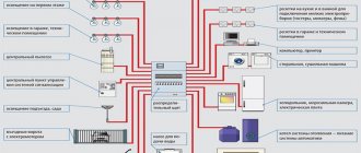
- Calculation of electrical wiring. Performed for power outlet groups, subject to the use of separate circuit breakers;
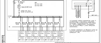
- Development of power supply schemes. This takes into account cable routes, cable types, calculations of circuit breakers and transformers. Stabilizers and other electrical equipment;
- Electrical calculation estimate. It is transferred to the customer along with the developed working design.
Create your patterns online
There are both free and paid web and mobile apps, but we are going to highlight two: one for ease of use and the other for its multi-platform mobile support.
EasyEDA
EasyEDA has as its main functions diagram design with an integrated library, circuit modeling and printed circuit design.
It has a software download version compatible with Windows 7 or higher, 32 and 64 bit for Linux 64 bit and for MacOS 64 bit. It also has an online version.
Introduction
The CSoft group of companies has been offering its clients tools for automating design work for many years. These solutions not only make the work of designers easier, but also improve the quality of work performed. Our group of companies constantly analyzes the software market and offers only the best to its clients. On April 2, CSoft Group announced a partnership agreement with Bentley Systems, a world leader in integrated software solutions to support the life cycle of infrastructure facilities. We are pleased to introduce Bentley Systems' electrical solutions software, promis•e V8i.
Collaboration technology
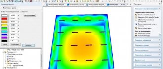
Joint parallel work on a 3D project is based on CADLib Project technology, which allows you to combine 3D models for various specialties in a common information space, load related models as a basis, and also use models of electrical consumers to lay power cables to them (Fig. 2) , create tasks linked to objects and conduct correspondence between project participants. Working in a single information space allows the electrical engineer to gain access to the objects of the model of builders and technologists (Fig. 3) and use these objects as a 3D substrate. Viewing fragments of the adjacent model is possible directly from the hierarchical structure of the project.
Rice. 2. Electrical lighting of a building in Model Studio CS Cable management
Rice. 3. Electrical lighting of a building with a 3D substrate of the building part in Model Studio CS Cable management
All participants in the design process work with the project database and standard element library databases deployed on a common server. Designers working in Model Studio CS connect to the project database from specialized applications using CADLib Project technology. This happens at the very beginning of the project, allowing further access to current settings and 3D models, as well as quickly publishing changes to a common database.
Rice. 4. Information model of the site in CADLib Model and Archive
Collective access to the complex BIM model and management of engineering data of the information model (Fig. 4), structuring, storage, visualization of information models, and their checking for collisions are carried out in the common data environment CADLib Model and Archive.
Calculations and integration capabilities
The Model Studio CS Cable Management software package provides the ability to exchange data with other software (Fig. 18):
- data exchange with EnergyCS Electrics for calculating short-circuit currents, voltage losses, etc.;
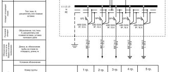
- data exchange with Model Studio CS Electrical diagrams for creating circuit diagrams, connection diagrams and calculations of short-circuit currents, voltage losses, etc.
Data exchange occurs through an Excel file with a CSV extension and is a regular table with the data necessary for calculations. The completed calculations are imported into Model Studio CS Cable Management, where cable rerouting is performed based on this information.
Rice. 18. Transferring data from a 3D model to other software
