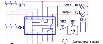
Hello! Rick here, engineer. Today I will talk about the use of insulation monitoring relays - a device that allows you to control current in DC, AC or rectified voltage circuits. The company produces insulation monitoring relay RKI-1 and leakage current monitoring relay RKTU-1 - these devices will help you detect leakage currents in a timely manner and take action.
Insulation damage can be caused by the following factors:
- physical aging of the material,
- mechanical damage,
- burning of the insulating layer due to poor-quality connection,
- destruction of insulation under the influence of climatic factors - temperature, moisture, solar radiation, etc.,
- contamination of insulation with oil, soot and chemically active materials that destroy the surface of the insulating coating.
Connecting an insulation resistance monitoring relay allows you to find out in time about a decrease in the quality of insulation and maintain the functionality of expensive electrical equipment.
What is an insulation monitoring relay
The insulation monitoring relay allows you to continuously monitor the circuit current (DC, AC or rectified voltage) and signal if the selected setting value is exceeded. The insulation resistance threshold is set using an adjustable potentiometer, front panel DIP switch or interface.
Most often, insulation monitoring relays are used for continuous monitoring of DC circuits at energy facilities, including gas protection of transformers, installed on electrical equipment with a transformer with an insulated neutral, excavators, cranes, etc. Specialized insulation monitoring relay circuits have been developed for mine equipment, which are supplied in explosion-proof design.
The relay is installed on the power side and when a ground fault or insulation current is detected, it turns off the input circuit breaker, turns on indicators with different lights, etc. Modern monitoring relays can transmit information about the parameters of the electrical network to the monitoring system. This is very convenient: with an extensive network of electrical equipment, the operator has the opportunity to track how the insulation resistance of the relay is measured in a specific section of the network, which greatly facilitates the search for and elimination of emergency situations.
220 (V) DC network insulation monitoring circuits
Hello, dear readers and guests of the Electrician's Notes website.
In today’s article I want to tell you about how 220 (V) DC insulation is monitored at the substations of our enterprise. Insulation control is what we call KIZ in short.
So, all our operational circuits are made on direct current.
Operating circuits include control circuits for high-voltage switches, relay protection and automation circuits (SHU buses), switching circuits or, in other words, circuits of solenoids (electromagnets) of switch drives (SHV busbars), emergency and warning alarm circuits (SHU busbars).
We also power the emergency lighting of substations from the DC switchboard (DCB), although there are no autonomous emergency lighting fixtures.
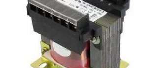
The source of direct current is rechargeable batteries (AB). Batteries are the most reliable power source, because... provide the necessary voltage to power operational circuits at any time of the day. True, for this you need to have a separate room, additional equipment in the form of charging and recharging units of the VAZP type and specially trained personnel to service them.
We still have SK-5 type lead-acid batteries installed at our substations. True, not so long ago we began to switch to new maintenance-free Varta batteries. I'll write about this some other time.
At remote substations, where it is not possible to power the operating circuits from a battery, BPN and BPT power supplies are used as a DC source.
The voltage level of operational circuits is generally 220 (V), less commonly 48 (V) is used, but this is quite the case in old substations.
Naturally, during operation it is necessary to control the insulation resistance of the “+” and “-” poles relative to the ground, otherwise in the event of a leak (short circuit) to the ground, depending on the nature of the short circuit, the control of the substation equipment may either fail (disappear), or vice versa, false shutdown or activation via bypass circuits.
To prevent such cases, it is necessary to control the appearance of “ground” in DC circuits. By the way, this is also stated in the PUE, paragraph 3.4.18:
Our direct operating current networks are very extensive, so we definitely cannot do without monitoring the insulation of their poles relative to the ground.
Damage to operational circuits must be identified and repaired as quickly as possible.
We use two insulation monitoring schemes:
- with two additional resistances and a milliammeter
- with two additional resistances, milliammeter and current relay
Now let's look at each scheme in more detail.
Circuit with two additional resistances and a milliammeter
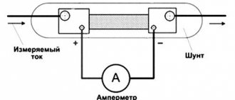
A simple circuit in which the “+” from the direct current switchboard (DCB) is connected to the output of one additional resistance (AR), and the “-” minus is connected to the output of another additional resistance (AR). On the other hand, their conclusions are connected to each other at a common (middle) point. The common (middle) point is connected to the grounding device (GD) of the substation through a milliammeter (mA).
Principle of operation
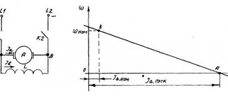
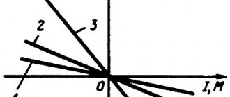
Current and voltage are the main operating parameters of any electrical installation, which means that monitoring them allows you to assess the performance of the equipment itself. A decrease in current in the network indicates a decrease in load, and an increase in it indicates both an increase in load (or overload) and the appearance of a fault. Long-term operation with an increased rated current is a clear signal of malfunction.
Current relays are focused on the minimum and maximum value of the threshold operating current and can be produced in electromagnetic, electronic and digital versions. Due to the simplicity of their design, electromagnetic relays are reliable and have a low price. The relay operates due to electromagnetic coupling, which is created when current passes through the coil. As the current increases and reaches a certain value, the EMF induced on the coil overcomes the resistance of the spring and the contacts close.
The operating principle of electronic RCT is based on a control circuit of one or two transistors (or thyristors limiting a resistor). The circuit provides for the presence of current conversion elements for power supply and a shutdown module, which can also have mechanical elements.
Visual diagrams
Digital devices are being used more and more often. Their operating principle is based on converting incoming information about current values into binary code, which makes it possible to monitor the gradual deterioration of insulation quality and remotely monitor the state of the network. Such devices are functional, have increased accuracy and wide settings for input parameters.
Operating diagram of RKTU-1 A
Scheme of operation of RKTU-1 B
Scheme of operation of RKI-1 A
Insulation monitoring relay NTK Priborenergo
Insulation monitoring relay RKI-1 DIN
The device is designed to measure the insulation resistance of the entire circuit and identify connections with damaged insulation. RKI-1 DIN allows you to control the resistance of each pole relative to the ground level, control the battery current, and monitor the decrease/increase in current on the operating current buses. RKI-1 DIN provides communication via RS-485 interface with the MODBUS RTU protocol.
RKI-1
Leakage current monitoring relay RKTU-1
A device that allows you to control current in DC, AC or rectified voltage circuits. RKTU-1 can monitor the leakage current and the quality of insulation of gas protection circuits - the fact that the relay is activated signals a significant decrease in the insulation resistance, turns off the gas protection and generates a signal to turn on the warning alarm. The setting of the threshold value of the operating current is set by a DIP switch on the front panel of the relay. RKTU-1 can be used at a rated voltage from 24 to 220 V.
RKTU-1
The products of NTK "Priborenergo" allow you to comply with the requirements of the PUE and provide protection for industrial electrical devices from deterioration of insulation quality and the appearance of leakage currents.
content .. 51 52 ..7.3. DEVICES FOR CONTROL OF ELECTRICAL NETWORK INSULATION AND PROTECTION AGAINST ELECTRICAL SHOCK IN MINES
For networks with an isolated neutral, devices have been used in practice that monitor the insulation resistance of the network phases relative to the ground by applying a constant control (operational) current (Fig. 65). Industrially produced current leakage protection devices (current leakage relays) for mine electrical networks with voltages of 127, 220, 380, 660 and 1140 V are built on this principle, the need for the use of which is prescribed by the Safety Rules.
According to the Safety Rules, the total shutdown time of a damaged network with voltages of 380 and 660 V should not exceed 0.2 s, and for voltages of 1140 V—0.12 s; other parameters of ground leakage protection devices for networks with voltages up to 1200 V are regulated by GOST 22929— 78 (ST SEV 2309-80).
The range of general network protection devices produced commercially for coal mines is given in Table. 28. In addition, starting units, which are the power source for hand-held electric drills and lighting installations, use their own protection unit, built into the shell of the unit and having parameters similar to the RU-127/220 device.
Rice. 65. A diagram explaining the principle of insulation monitoring and protective shutdown and using an operating current source.
28. Nomenclature of general network protection devices used
in coal mines
The devices RU-127/220, RU-380 and AZUR1 have an explosion-proof design corresponding to the RV level, the devices RU-1140, AZUR2 and AZURZ are made in the form of blocks built into mobile substations [4; 8].
According to the Safety Rules, protective shutdown of a network with voltages up to 1140 V must be carried out by one leakage current relay protection device in combination with a switching device for the entire electrically connected network (connected to one or a group of parallel operating transformers). When the current leakage relay is triggered, the entire network connected to the specified transformers must be disconnected, with the exception of a piece of cable no more than 10 m long connecting the transformer to the general network device (circuit breaker).
It is impossible to include several leakage relays in one network due to mutual influence on each other and possible disruption of the protection.
The operating principle of the protection devices is as follows (Fig. 65). One of the terminals of the device is connected to the three-phase network through the relay winding K1 and a three-phase connecting filter with resistance Zph, the source G of which provides the control (operational) current. The second terminal of the device, coming from this source, is connected to ground. The closing contact K1.1 of relay K1 is connected to the circuit of the tripping coil K2 of the general-network circuit breaker Q. Thus, there is an operating voltage between all phases of the network and the ground. The connecting filter, in addition to ensuring the supply of voltage from the operational source G to three phases, limits the alternating current of the network, which can flow through the control circuit to the ground.
The principle of monitoring insulation resistance, applied in the leakage relay circuit of the RU-127/220 device with self-monitoring of circuit elements (Fig. 66, a), is that the operating current source (rectifier V) through current-limiting resistors RB is connected between the three phases of the network and ground parallel to the network insulation resistance and the measuring relay K, connected between the zero point of resistors Rf and additional grounding D3. The higher the insulation resistance, the higher the operational current flowing in the circuit of the relay winding K. When the insulation resistance of the network is high, relay K holds its armature; when the resistance decreases, the part of the operating current that branches off along the leakage circuit increases, and the current in the relay circuit decreases and, with an insulation resistance equal to the setting of the disconnecting resistance, becomes equal to the return current of the relay, and the latter releases its anchor. Then relay K with its contacts acts on the control circuit of the magnetic starter and causes the network to shut down.
The principle of self-monitoring of the health of the leak relay circuit elements is that it reacts not to an increase, but to a decrease in the current in relay K, therefore, damage to the leak relay circuit, leading to a decrease or complete disappearance of the current in relay K, causes a corresponding increase in the leak relay setting or network outage.
To create in the winding of the measuring relay K1 (Fig. 66, b) a current sufficient to attract its armature, the S2 Charging button is used in the leakage relay circuit, when pressed, the limiting resistors R11 R11 are bypassed and the current in the winding of relay K1 increases. The latter closes its contacts in the starter control circuit. In the absence of leaks in the network, the operating current flows through the circuit: limiting resistors R4—R9—diodes VI—V3—resistors R10 and R11—clamp B—additional grounding D3—capacitor C—relay K1—resistor R15—resistors R12—R14. When the insulation resistance of the circuit decreases below a critical value, relay K1 releases its armature and opens the contacts, influencing the control circuit of the magnetic starter.
Rice. 66. Simplified (a) and schematic diagram (b) of the device (leakage relay) RU-127/220 with self-monitoring of serviceability.
To check the serviceability of the leakage relay, you must press the St button. Check what creates a single-phase leakage through resistor R1 at a network voltage of 127 V or resistors R1 and R2 at a voltage of 220 V. When the leakage relay is connected to a network with a voltage of 127 V, resistors R2, R10 and R15 are bypassed.
To put the leakage relay of the RU-127/220 device into operation, you must turn the handle of the locking switch to the On position and lock it with the locking screw. In this case, the manual starter PRV (PRSh) must be turned off. By pressing the Start button of the KUV-22 (KUV-12) push-button station, the PMVI-13M magnetic starter is turned on. If, after releasing the Start button, the starter turns off immediately, this means that the measuring relay K1 did not attract its armature and did not close contact 1 (1,2 in the starter control circuit. In this case, you must repeat the operation of turning on the starter using the Start button, but at the same time you should press the Cock button on the cover of the device. In this regard, the KUV-22 push-button station should be installed in close proximity to the leakage relay.
After turning on the PMVI-13M starter, the leakage relay is energized by 127 V (220 V) and you can turn on the manual starter PRV (PRSh).
A simplified diagram of the device (leakage relay) RU-380 with self-monitoring for a mains voltage of 380 V is shown in Fig. 67, a. The leakage relay consists of a three-phase transformer Tru source of operational current, assembled from diodes V8-V10, limiting resistors R12, R13y R17, an auxiliary current source consisting of diodes V2y V6, V7 at a two-winding relay K1, zener diode V4, smoothing capacitors C1 and C4.
The operating current source is connected between the ground and the network phases using a transformer Tr, as well as to an insulation monitoring circuit consisting of a zener diode V4, windings 1, 2 of a two-winding relay K1 and a connection filter (primary windings of the transformer Tr). The leakage resistance RyT is connected in parallel with the insulation control circuit, so the current in windings 1, 2 of relay K7 reaches its greatest value at high insulation resistance. Windings Zu 4 of the two-winding relay K1 are connected to an auxiliary current source.
The windings of the leakage relay are connected in such a way that their magnetic fluxes are directed in the opposite direction, and the magnetic flux of the auxiliary winding is greater than the magnetic flux of the main winding, but the difference in magnetic fluxes is not sufficient to attract the relay armature. As the insulation resistance of the network decreases due to its shunting action, the current in the main winding decreases and when the insulation (or leakage) resistance is equal to the actuation resistance, the resulting magnetic flux becomes sufficient to operate the relay. At the same time, with its contact it acts on the circuit of the disconnecting coil of the switching device (feeder circuit breaker), which disconnects the network with damaged insulation.
Due to the fact that the leakage relay reacts to the difference in the magnetic fluxes of the main and auxiliary windings, any damage to the leakage relay circuit, leading to a decrease or complete disappearance of the current in one of the windings, causes either an increase in the operating resistance or a network shutdown. This is the principle of self-monitoring of the serviceability of the elements of the leakage relay circuit.
content .. 51 52 ..