A huge number of electrical appliances used in everyday life and industry base their operation on determining the level of ambient temperature. The measuring element in them is a temperature sensor that is triggered when heated or cooled to a set level. They can be purchased in most stores; they are included with ovens, controllers and other devices, but it is much more interesting to make a thermostat with your own hands.
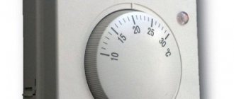
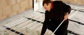
Example of a simple thermostat
Next, we will look at the principle of operation and options for making such a homemade product.
Where can combined systems be made?
The area and number of floors in our example are very arbitrary. It is also necessary to coordinate their operating modes.
It’s one thing: connecting a radiator heating system to a boiler when all the functionality for this is already included in the boiler. They propose to install polypropylene supply and return pipes in a layer of sand under the screed along the foundation. It can be single-pipe or double-pipe.
In some situations, when all the radiators are closed and the heated floor is running, the boiler pump and the underfloor heating pump work sequentially, interfering with each other. Installation of combined heating in a system with a gas boiler The most difficult moment in the process of installing combined heating is the need to supply coolant with different temperatures from the manifold for the heated floor and radiators through two pipes. Depending on the temperature at the outlet of the in-floor circuit, the mixing valve opens or closes, increasing or decreasing the amount of hot coolant from the supply in the recirculation circuit.
This is necessary to ensure the tightness of all joints made. Air heat pump is the main source of heat Air heat pump Before considering the positive and negative aspects of existing heating units, let's talk a little about air heat pumps.
Where can combined systems be made?
The collector is mounted in a special box made of galvanized steel that matches its size. In this case, the type of coolant or heat source does not matter.
Designation of the main elements of the circuit: wall-mounted gas boiler with built-in circulation pump and expansion tank; hydraulic separator thermo-hydraulic separator or hydraulic arrow ; collector - collector beam for connecting heating circuits; radiator heating circuit circulation unit; mixing unit kennel water thermoplastic floor; safety thermostat. The three-way thermostatic valve of the second type is distinguished by the fact that it provides regulation of the supply intensity of only the hot flow. In more complex systems, the controller is also guided by a weather sensor, making a preventive change in the heating power.
4 Proven water heated floor connection diagrams
As a result, the coolants are mixed as follows: liquid from the return pipe is supplied continuously, and hot liquid is supplied only when necessary. In this case, the in-floor structures will be durable, reliable and durable.
A special heat-sensitive device is used. Heating with a solid fuel boiler Combined heating with a solid fuel boiler is a closed gravity system with a heat storage device. We combine heating. Warm floor + radiators. A simple solution
Installation and connection of the thermostat
The thermostat is usually mounted into the wall, like a regular switch. A place is selected for it near the existing electrical wiring, for example, near an outlet. First, a recess is made in the wall, a thermostat mounting box is installed there, and the wires (phase and neutral) of the power supply and temperature sensor are connected to it. The next step is connecting the thermostat.
There are “sockets” located on the side of the thermostat. The wires of the network (220V), sensor and heating cable are supplied here.
General thermostat connection diagram
It is useful to know that the wires that are connected when installing the thermostat are color coded:
- white (black, brown) wire – L phase;
- blue wire – N zero;
- yellow-green wire - ground.
Connecting the heated floor to electricity is carried out in the following order:
- Network wires with a voltage of 220V are connected to “sockets” 1 and 2. Polarity is strictly observed: wire L (phase) is connected to contact 1, wire N (zero) is connected to contact 2.
- A heated floor heating cable is connected to contacts 3 and 4 according to the principle: 3 contact - wire N (zero), 4 contact - wire L (phase).
- The wires of the temperature sensor (usually built into the floor, that is, determining the temperature in the thickness of the floor) are connected to “sockets” 6 and 7. Polarity principles do not need to be observed here.
- Check the functionality of the thermostat. To do this, turn on the -220V power supply, set the minimum temperature on the device and turn on the heating element system (by turning the knob or pressing the button). After this, the heating mode is changed to maximum, that is, the thermostat is “programmed” to the highest temperature that is possible for it. The correct operation of the device will be indicated by a click, which will indicate that the heating circuit is closed.
Connection diagrams may vary slightly depending on the types and models of thermostats. Therefore, so that the user does not make a mistake, all contacts are usually marked on the device body.
When connecting the thermostat, follow the connection diagram shown on the device body
Small differences in connection are also dictated by the characteristics of underfloor heating cables. According to their structure and number of cores, they are divided into single-core and double-core. Accordingly, there are some nuances in their connection diagrams.
Connecting a two-core cable to the thermostat
A two-core heating cable has two current-carrying conductors under a protective sheath. This type of cable is more convenient than a single-core design, since it is connected to the thermostat only from one end. Let's look at a typical connection diagram:
Connection diagram of a two-core cable to a thermostat
We see that in one two-core cable there are 3 wires adjacent: 2 of them are current-carrying (brown and blue), 1 is grounding (yellow-green). The brown wire (phase) is connected to pin 3, the blue wire (zero) is connected to pin 4, and the green wire (ground) is connected to pin 5.
The thermostat kit, the circuit of which we just looked at, does not include a grounding terminal. If there is a grounding terminal, installation is much simpler.
Two light green wires are connected to the ground loop through the PE terminal
Connecting a single-core cable
A single-core cable has only one current-carrying conductor, usually white. The second wire - green - is the grounding of the PE screen. The connection diagram could be like this:
Connection diagram of a single-core cable to a thermostat
White wires (both ends of a single-core cable) are connected to thermostat contacts 3 and 4, and a green ground wire is connected to contact 5.
Using a thermal sensor on Arduino
To assemble a temperature meter based on an Arduino microcontroller, you need to prepare the following:
The DS18B20 digital temperature sensor is a device that not only signals when a specified temperature threshold has been exceeded, but can also store measurement values. The sensor chip has three output contacts - “+”, “−” and a signal wire. The waterproof temperature sensor is used to measure the heating of water or liquids.
A temperature sensor can always be purchased, like an Arduino board, in online stores. The digital module is connected to Arduino via GND channels, and the Vdd output is connected to 5V, Data to any Pin. For a clearer understanding, the connection diagram of the DS18B20 digital sensor to Arduino is shown in the photo below.
Heating element with thermostat for water heater
Today, modern household water heaters successfully cope with the problem of lack of hot water supply. The design of any such device necessarily includes a heating element - a tubular metal rod. It is he who converts electrical energy into thermal energy and then gives it to water, heating it to the desired temperature. The thermostat built into the heating element allows you to set the degree of water heating.
A heating element with a thermostat is a device of simple design. It consists of several elements, namely:
A metal tube, the material of which can be titanium, steel, brass or copper with a protective coating against corrosion.
Inside the tube there is a spiral of wire, which has a high resistivity, which means that when an electric current passes through it, it can become very hot.
Insulating filler is a material that is designed to prevent the spiral from coming into contact with the walls of the tube.
Contact rod, which serves to connect the heating element to the electrical network;
Porcelain insulators located at the ends of the tube;
Thermal sensor (temperature regulator), which turns off when the set temperature is reached, and turns on again when the water cools down to the lower mark, and so on all the time the water heater is in the on mode.
A water heating element with a thermostat has significant advantages that will ultimately help optimize the water heating process from a financial point of view:
- Thermostats for heating elements allow rational use of resources. When the water in the water heater reaches the set temperature, the heating element turns off and turns on when the water has cooled significantly.
- Simplicity and reliability of design. The water heating element with a thermostat is designed for continuous operation for several years.
- Easy installation. Each water heater model has a special mount for the heating element. Some models provide the ability to use several heating elements simultaneously.
- The low price of a heating element with a thermostat makes it the optimal solution.
Tubular metal heating elements have only a few significant disadvantages. One of them is that if the heating element burns out, it cannot be repaired; it will have to be completely replaced. In addition, with constant contact with water, scale forms on the metal surface of the heating element, which reduces the efficiency of heat transfer. Also, such heating elements often suffer from voltage surges.
Thermostats for heating elements can be of several varieties. First of all, they are divided into mechanical, their action is based on the properties of various metals when heated, and electronic, based on a sensor.
Water heaters with a thermostat are also available in various designs, differing from each other in the material of manufacture and the method of installation on the water heater.
You can buy a heating element with a thermostat in Moscow for installation in water heaters and other household appliances. In our catalog you will find different models of heating elements that are suitable for all types of modern water heaters, boilers, washing machine tanks, tanks, etc.
We supply heating elements directly from the manufacturer, which allows us to keep prices low and be able to quickly supply the necessary devices in the required quantity. Each large customer can count on individual terms for calculating costs.
Legal address: 117105, Moscow, Varshavskoe highway, no. 26, building 2, floor 2, office 86
Indoor control
It is possible to control the thermostat in several rooms.
Typical thermostat circuit for a cellar.
Devices are designated by Latin letters and numbers. For example, LM135. In order not to make a mistake in your choice, remember: 1 - application in military equipment, 2 - application in production apparatus and devices, 3 - application in household appliances. The Russian analogue is the designation of transistors - 2T (military) and KT (mass). The operating principle of such a sensor is as follows: as the temperature rises, the stabilization voltage increases, that is, it is a zener diode. You can make sure you made the right choice by reading the technical specifications of the device. The calibration point is indicated in Kelvin. The temperature scale is indicated in degrees Celsius.
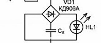
Schematic diagram of the thermostat.
In practice, it will be supplemented with an output device for turning on the heater, a power supply and an operation indicator.
The next important element is a comparator, for example LM311. It has two inputs - direct (2), designated “+”, and inverse (3), designated “-”, and one output. In the diagram, the comparator output is indicated by the number 7. This device works like this: the voltage at input 2 is greater than at input 3, and we get a high level at the output. The transistor opened and connected the load. A potentiometer connected to the direct input sets the temperature - sets the response threshold of the comparator. In the opposite situation (the voltage at input 2 is less than at input 3), the output level decreases. The temperature rises, the thermal relay is triggered, the comparator goes to a low level, the transistor closes, the heating element turns off. This cycle repeats continuously.
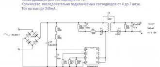
Hello to all fans of electronic homemade products. Recently I quickly made an electronic thermostat with my own hands; the circuit diagram of the device is very simple. An electromagnetic relay with powerful contacts that can withstand current up to 30 amperes is used as an actuator. Therefore, the homemade product in question can be used for various household needs.
According to the diagram below, the thermostat can be used, for example, for an aquarium or for storing vegetables. Some may find it useful when used in conjunction with an electric boiler, while others may use it for a refrigerator.
Typical thermal relay circuit
The basis of the design is the LM335 temperature sensor or its analogues, as well as the LM311 compressor. The thermal relay circuit is supplemented by an output device, to which a heater with the installed power is connected. A power supply must be present; indicators can be used if necessary.
A more complex circuit includes transistors, a relay, a zener diode and a capacitor C1, which smoothes out voltage ripples. Current equalization is carried out using a parametric stabilizer. In this case, the device can be powered from any source whose parameters match the relay coil voltage in the range from 12 to 24 volts. The power supply can be stabilized using a conventional diode bridge with a capacitor.
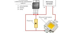
DIY temperature controller: power and load
As for the connection of LM 335, it must be serial. All resistances must be selected so that the total current that passes through the temperature sensor corresponds to values from 0.45 mA to 5 mA. The mark should not be exceeded, as the sensor will overheat and show distorted data.
The thermostat can be powered in several ways:
- Using a power supply oriented at 12 V;
- Using any other device whose power supply does not exceed the above figure, but the current flowing through the coil should not exceed 100 mA.
Let us remind you once again that the current in the sensor circuit should not exceed 5 mA; for this reason, you will have to use a high-power transistor. KT 814 is best. Of course, if you want to avoid using a transistor, you can use a relay with a lower current level. It can operate on a voltage of 220 V.
Connection diagram
Almost all thermostats existing on the modern market are relay. This means that they operate via a relay that opens and closes contacts based on a temperature preset by the user. As a theoretically connected thermostat, we will use an electric relay-type thermostat with dry contacts. Dry contacts are a term that means that in any state, closed or open, there is no voltage across the contacts.
To connect to the boiler, there are terminals on the thermostat; you need to connect the open and common ports. If they are not indicated in the manual for your specific model, you just need to ring the contacts with a tester. Next, we need to make sure that the thermostat can be connected to the boiler. Usually this is indicated directly in the technical documentation; if there is none, then the information can be easily found in any of the search engines.
The found electronic circuit diagram of the board indicates the location of the very jumper into which the thermostat will be connected to the boiler. Depending on the boiler model, you will have to unscrew several bolts to get to the required part. The block can be installed either on the control board or taken out separately. Connecting the thermostat for any of these options will be no different.
Next, you need to pull out the jumper, and in its place put the cable supplied with the thermostat (or purchased separately). This is a two-core wire with a cross-section of at least 0.75 square millimeters. The polarity when connecting does not matter. The cable is connected to the thermostat control unit into the normal open and common ports, as described above. The ports are located on one side of the control unit, and on the other there are ports for connecting the power supply cable. You can either purchase a new cable of the desired cross-section or use the complete one.
This completes the connection of the thermostat to the gas boiler. All that remains is to check the functionality of the system. On the thermostat we set the required air temperature in the room, the signal is transmitted to the control unit and, depending on the set temperature, the relay contacts close or open. When setting a temperature that is lower than the current one, the burner starts heating the water in the system; when setting a temperature higher, the burner, on the contrary, starts working.
Why the heater does not heat up - troubleshooting
If suddenly the heater stops working and the power connection indicator does not light up, then first of all you need to check the presence of supply voltage in the electrical outlet. The circuit breaker at the entrance of the electrical wiring to the apartment could have tripped, the contact at the point where the wires are connected to the socket could have broken, or the electrical socket itself could have failed.
You can check the serviceability of the outlet in two ways by connecting any electrical appliance to it, such as a table lamp or hair dryer, which is preferable. Or connect the heater to a different outlet. If the heater starts to heat up, it means the socket is faulty.
If the problem is with the heater, then it is quite possible that it has overheated and its overheat protection system has tripped, or the plug was inserted into the socket, but they forgot to turn on the switch on the heater body or set the temperature control knob to the desired position (if any). Therefore, before drawing conclusions, you need to check what position the switches are in and wait until the heater cools down.
If all checks are unsuccessful, it means that the heater is out of order and requires repair.
Types of household water heaters
Features of connecting household heaters are directly related to the types of devices, their technical parameters, and overall dimensions.
Traditionally, two types of heaters are used in household practice:
Both types of boiler systems differ from each other in heating technology.
With storage heaters, cold water is collected in a container, heated and then discharged for tapping.
With flow-through units, heating is carried out directly during the flow of cold water in contact with the heater, without collecting liquid in a storage tank.
Household consumers mainly use storage boiler systems. A comparative review of both types of water heaters is given in this article.
Technical device of the storage boiler
A storage-type water heating system, boilers, in a simplified schematic form is a container equipped with electric heating elements or liquid heat exchangers. The storage vessel has pipe lines for cold water supply and hot water outlet.
The designs of indirect heating boilers are additionally equipped with a working coolant area and heating connection lines.
Any modern system, regardless of its design features, is equipped with automation, thanks to which the water heating temperature and the operation of the system as a whole are regulated.
Structural design of heating devices
There are designs of storage boilers designed for installation vertically (wall-mounted) and horizontally (floor-mounted). Of course, each individual case of using certain boilers has its own installation features.
So, if it is planned to install a water heating device on a wall, a preliminary calculation of the load and comparison of the results obtained with the design parameters of the wall of the room on which the device is to be mounted is necessary.
Installing equipment without load calculations threatens to result in a fatal installation error, when a filled boiler can simply collapse along with the flimsy partition on which it was mounted.
According to the equipment instructions, the load must be calculated taking into account four times the weight of the boiler system.
Therefore, if the structure of the supporting wall is frankly weak, the water heater circuit must be supplemented not only with connection lines to the water supply and coolant, but also with reinforced racks - through fasteners.
In classic connection diagrams for wall-mounted boilers, the water supply/discharge pipes of heating devices are marked with the appropriate color – blue/red.
Types of thermostats by design.
- In the building.
- For installation box.
- Without a normal body.
- In the form of a socket.
1. In a wall-mounted housing.
2. For installation in a regular installation box.
3. Without a normal body.
The first and second versions can be used normally in the room.
The third type of design cannot be normally installed in a residential area without additional costs, only in a garage or chicken coop.
Such thermostats are discussed in detail in this review of thermostats.
4. In the form of a socket.
The thermostat looks like a tee, but with one socket.
There are three possible operation options for the thermostat:
In one housing there is a switching device and controls.
The socket does not contain controls and is controlled via a radio channel by an external thermostat.
In one case there is a switching device and controls with the ability to configure via Wi-Fi.
| Wireless WiFi Thermostat RF Plug Remote Control Smart Home | Nashone LCD Digital Programmable RC Wireles Thermostat for underfloor heating |
| Pymeter Digital Thermostat PID Temperature Controller | Nashone Thermostat Temperature Controller |
Sequence of work
Having mounted the circuit in the chosen way, you should install the sensor in such a way that, during operation, it controls the temperature of the required object.
- The variable resistor should be installed in such a way that it can be easily accessed.
- After that, you need to put a scale of set temperatures that will be maintained by the thermostat.
After all this work has been completed, connect the power cord to the device (if you do this earlier, it will greatly interfere with operation).
After assembling and configuring the device, it is placed in the housing.
Model overview
Capillary thermostats for domestic use must be reliable, durable, and have a simple connection diagram. Next, a description of the 3 most suitable thermostats for domestic use will be given.
AZT-6
Mechanical thermostat. Main purpose: temperature control of water heaters. The device is equipped only with a knob for adjusting the operating temperature. Operates in modes - 15 + 85 degrees C.
Among the advantages:
- Easy to connect.
- Fast cut-off.
- Miniature appearance.
- Low price.
AZT-6 is an excellent assistant for monitoring air temperature changes in the house.
Ballu BMT-2
Temperature controller for heaters and ventilation systems. Operating range +5–35 °C. The device is used to switch between heating devices and ventilation systems. Has a built-in notification about changing the operating mode. Can be used to connect 4 devices at once into a common system, with their subsequent division according to temperature conditions.
Pros:
- High reliability.
- Ease of Management.
- Multiple connection pairs.
- Not a high price.
The Ballu BMT-2 regulator can be trusted to control the temperature in the house with an electrical load of more than 10 amperes.
Terneo EG
The device is designed to control the temperature in the incubator. The model is completely electronic. Has an additional socket on the body. Working in incubators is not the only purpose of this model. It can be used for work in warehouses and basements.
Pros:
- Easy setup of parameters.
- Easy to read display.
- Availability of sound notification about operation.
- Additional socket.
Terneo EG is very reliable. Through this device, you can connect several devices and set the response temperature for each device.
General concept of temperature controllers
Devices that record and simultaneously regulate a given temperature value are more common in production. But they also found their place in everyday life. To maintain the necessary microclimate in the house, water thermostats are often used. They make such devices with their own hands for drying vegetables or heating an incubator. Such a system can find its place anywhere.
In this video we will find out what a temperature regulator is:
In reality, most thermostats are only part of an overall circuit, which consists of the following components:
These are the three main parts of the system for maintaining specified temperature parameters. Although, in addition to them, other parts, such as an intermediate relay, may also participate in the circuit. But they perform only an additional function.
How to connect a room thermostat to a gas boiler?
To install the regulator, you do not need any professional skills or special tools; you just need to understand the installation diagram, follow the instructions of the gas boiler and regulator manufacturer, and follow safety precautions when working with electric current. Then the installation can be done independently, without the help of a specialist.
Connection diagram
The diagram of the gas boiler must indicate whether it is possible to connect a thermostat to it
It is important to make sure that the installation of additional equipment is permitted by the manufacturer and will not harm the heating system
Incorrect installation can lead to breakdown of expensive equipment and loss of warranty.
In the case where the control unit will be installed inside the boiler, find a suitable place for it. If necessary, you can use an installation box.
Important! When connecting a thermostat, it is strictly necessary to comply with the requirements of the boiler manufacturer!
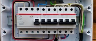
If you study the diagram of the main board of a gas boiler, you will see that there are two contacts on it, connected by a jumper, where the electric current first leaves the board and then returns to it, controlling the switching on and off of the heating boiler. In many modern models, for ease of installation, this jumper is located on a separate terminal block, where the thermostat is simply connected.
Photo 1. Printed circuit board of a gas boiler. The part circled in red shows the possibility of connecting various thermostats.
But on some types of heating equipment you will have to look for the installation location directly on the board. In this case, unscrew the screws that hold the jumper, remove it, and install the wires going to the thermostat in this place.
A correctly connected thermostat passes through itself an electric current going to the boiler from the network, thus controlling the switching on and off of the entire heating system. If the air in the room is heated more than what was set on the regulator during its setting, the device turns off the gas boiler, and when the temperature drops below the specified limit, the heating turns on again and the air in the house is heated.
Materials and tools
To install the thermostat to a gas boiler, no special tools are required. Everything that is necessary to install the device in the heating system is included in the delivery kit.
To install the regulator, you will need technical data sheets for the thermostat and heating boiler to verify electrical connection diagrams, a household screwdriver, a tester to check the presence of voltage in the network, and a set of tools for mounting the device on the wall in a living room.
Choosing a location to install the thermostat
Before starting installation work, select the location for installing the thermostat
Choosing the right room for the device is extremely important, because it is the temperature and humidity of the air in this room that will regulate the entire heating system in the house
The thermostat must be installed in a residential area, and not in a technical one. Usually choose the coldest room in the whole house, for example, the corner. Installing the device in a boiler room or pantry will lead to incorrect heating operation. Do not hang the regulator near heating radiators or household appliances that emit thermal interference: stoves, heaters. It is not recommended to place the regulator in a draft, near windows, or where it will be exposed to direct sunlight.
The thermostat should be easily accessible and visible so that you can change the temperature settings or replace the batteries at any time.
Installation rules:
- The installation height is no more than one and a half meters above floor level.
- Do not install on an external, cold wall of the house.
- The device must be freely accessible.
- Do not hang near stoves, air conditioners, or windows.
- Do not expose the device to direct sunlight.
Effective heating control is a vital part of running your boiler and home heating system efficiently. Proper use of controls will reduce the energy consumption of the unit, while creating a comfortable temperature in every room of the house, avoiding overheating of the premises
A thermostat (or programmer) controls the operation of the boiler depending on the room temperature.
Up to 20% of the volume of energy consumed can be saved by using this type of automation. And energy prices are quite high and every normal person wants to reduce their expenses.
We consider a situation where the boiler is calculated correctly, the necessary insulation of the premises has been completed, and the heating system is functioning normally.
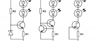
Thermal sensor on germanium diodes
A feature of germanium semiconductor diodes is their high sensitivity to changes in air temperature. Therefore, these radio components can be used as temperature sensors when they are turned back on.
Their use is explained by the strong dependence of the reverse current on the ambient temperature. This feature of the diodes is used in a simple cooler speed controller circuit.
Germanium diodes connected in parallel (3–4 pieces) are connected in the opposite direction to the base circuit of the composite transistor. Their glass cases can be mounted directly on the cooler without any heat sinks. Resistor R1 protects the transistor from thermal breakdown, and R2 determines the response threshold of the regulator. If the fan does not turn on when the room temperature is exceeded, then the number of diodes must be increased. When the cooler begins to rotate the blades at high speed, the number of radio components is reduced.