4.2
Average rating: 4.2
Total ratings received: 82.
4.2
Average rating: 4.2
Total ratings received: 82.
A conductor carrying electric current always generates a magnetic field. To describe it, various quantities are used, one of which is induction. Let's take a closer look at this concept.
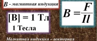
Physical meaning of magnetic induction
Physically, this phenomenon is explained as follows. The metal has a crystalline structure (the coil is metal). The crystal lattice of a metal contains electrical charges - electrons. If there is no magnetic influence on the metal, the charges (electrons) are at rest and do not move anywhere.
Dmitry Petrovich VasilievProfessor of Electrical Engineering, St. Petersburg State Polytechnic University If a metal comes under the influence of an alternating magnetic field (due to the movement of a permanent magnet inside the coil - an exact displacement), then the charges begin to move under the influence of this magnetic field.
As a result, an electric current is generated in the metal. The strength of this current depends on the physical properties of the magnet and coil and the speed of movement of one relative to the other.
When a metal coil is placed in a magnetic field, the charged particles of the metal lattice (in the chestnut) are rotated through a certain angle and placed along the magnetic field lines.
The greater the magnetic field strength, the greater the number of particles rotating and the more uniform their arrangement will be.
Magnetic fields oriented in one direction do not neutralize each other, but add up to a single field.
Inductance
Electric current passing through a conductor creates a magnetic field around it. The magnetic flux ( Phi ) through the loop of this conductor is proportional to the induction module ( vec{B} ) of the magnetic field inside the loop, and the magnetic field induction, in turn, is proportional to the current strength in the conductor.
Therefore, the magnetic flux through the loop is directly proportional to the current in the loop:
Inductance is a coefficient of proportionality ( L ) between the current strength ( I ) in the circuit and the magnetic flux ( Phi ) created by this current:
Inductance depends on the size and shape of the conductor, on the magnetic properties of the environment in which the conductor is located.
The SI unit of inductance is henry (H). The inductance of the circuit is 1 henry if, at a direct current of 1 ampere, the magnetic flux through the circuit is 1 weber:
We can give a second definition of the unit of inductance: an element of an electrical circuit has an inductance of 1 H if, with a uniform change in the current in the circuit by 1 ampere in 1 s, a self-inductive emf of 1 volt occurs in it.
Magnetic flux
Magnetic flux is a scalar quantity that characterizes the effect of magnetic induction on a given metal circuit.
Magnetic induction is determined by the number of lines of force crossing 1 cm2 of metal section.
The magnetometers used to measure it are called teslometers.
Abramyan Evgeniy Pavlovich Associate Professor, Department of Electrical Engineering, St. Petersburg State Polytechnic University The unit of measurement of magnetic induction in the SI system is Tesla (T).
After the movement of electrons in the coil stops, the core, if it is made of soft iron, loses its magnetic properties. If it is made of steel, it may retain its magnetic properties for some time.
Magnet interaction
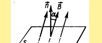
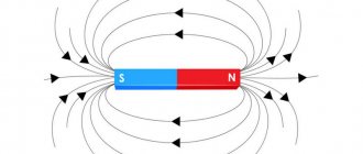
A permanent magnet (or magnetic needle) is oriented along the Earth's magnetic meridian. The end pointing north is called the north pole (N), and the opposite end is called the south pole (S). Bringing two magnets closer, we notice that like poles repel each other, and opposite ones attract (Fig. 1).
If we separate the poles by cutting a permanent magnet into two parts, we will find that each of them will also have two poles, that is, it will be a permanent magnet (Fig. 2). Both poles - north and south - are inseparable from each other, equal.
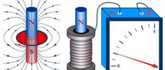
The magnetic field created by the Earth or permanent magnets is represented, like an electric field, by magnetic lines of force. An image of the magnetic field lines of a magnet can be obtained by placing a sheet of paper on top of it, onto which iron filings are poured in an even layer. When exposed to a magnetic field, sawdust becomes magnetized: each of them has a north and south pole. The opposite poles tend to move closer together, but this is prevented by the friction of the sawdust on the paper. If you touch the paper with your finger, the friction will decrease and the filings will be attracted to each other, forming chains that represent magnetic field lines.
In Fig. Figure 3 shows the position of a straight sawdust magnet in the field and small magnetic arrows indicating the direction of the magnetic field lines. This direction is taken as the direction of the north pole of the magnetic needle.
MI vector direction
The direction of magnetic fields can be indicated by a magnetic needle placed within the fields. It will spin all the way. The northern end of the arrow will show where B → the unit vector of a particular field is oriented.
Magnetic induction lines
The frame with the current one behaves in exactly the same way, being able to move in the MP without interference. The direction of the induction vector indicates the orientation of the normal to such a closed electromagnetic circuit.
Attention! The gimlet rule (right screw) is used here. If the screw rotates in the same way as the current is directed into the frame, then the forward movement of the screw coincides with the direction of the positive normal.
In some cases, the right-hand rule is used to find direction.
Visual display of MI lines
The line to which a tangent can be drawn, coinciding with point B →, is called the magnetic induction (MI) line. Using such lines, you can visualize the magnetic field. These are closed circuits that block currents. Their density is always proportional to the value of B → at a certain point in the MP.
Information. As for the MF of direct motion of charged particles, these lines are presented in the form of concentric circles. Their center is located in a straight line with the current and in planes located at right angles to it.
The direction of magnetic lines can also be determined using the suspension rule.
Basic formulas for calculating the MI vector
The magnetic induction vector, the formula of which is B = Fm / I * ∆L, can be found using other mathematical calculations.
Law of Electromagnetic Induction
The law of electromagnetic induction (Faraday's law) sounds like this:
The induced emf in a closed loop is equal and opposite in sign to the rate of change of the magnetic flux on the surface bounded by the ring.
Mathematically, this can be described by the formula:
| Faraday's law Ɛi – induced emf B ΔФ / Δt – rate of change of magnetic flux W/s |
The “-” sign in the formula allows you to take into account the direction of the induction current. The induced current in a closed circuit is always directed in such a way that the magnetic flux of the field created by this current through the surface bounded by the ring reduces those field changes that cause the appearance of the induced current.
If the circuit consists of N turns (i.e. it is a coil), the induced emf will be calculated as follows.
| Faraday's law for a circuit of N turns Ɛi – induced emf B ΔФ / Δt – rate of change of magnetic flux W/s N – number of revolutions |
The strength of the induction current in a closed conductive circuit with resistance R:
| Ohm's law for a conducting circuit Ɛi – induced emf B I – induction current strength [A] R – circuit resistance [Ohm] |
If a conductor of length l moves with speed v in a constant uniform magnetic field with induction B, the emf of electromagnetic induction will be equal to:
| Induction EMF for a moving conductor Ɛi – induced emf B B – magnetic induction [T] v – conductor speed [m/s] l – core length [m] |
The appearance of an inductive electromagnetic field in a conductor moving in a magnetic field is explained by the action of the Lorentz force on free charges in moving conductors. In this case, the Lorentz force plays the role of an external force.
A conductor moving in a magnetic field through which an induced current flows experiences magnetic braking. The total work done by the Lorentz force is zero.
The amount of heat in the circuit is released both due to the work of an external force, which keeps the speed of the conductor constant, and due to a decrease in the kinetic energy of the conductor.
A change in the magnetic flux entering a closed loop can occur for two reasons:
- due to the movement of a circuit or its parts in a constant magnetic field over time. This is the case when conductors, and with them free charge carriers, move in a magnetic field
- due to changes in time of a magnetic field with a stationary circuit. In this case, the occurrence of induced emf can no longer be explained by the action of the Lorentz force. The phenomenon of electromagnetic induction in stationary conductors, which occurs when the surrounding magnetic field changes, is also described by Faraday's formula
Consequently, the phenomena of induction in moving and stationary conductors proceed in the same way, but the physical reason for the occurrence of induction current in these two cases turns out to be different:
- in the case of moving conductors, the induced emf arises due to the Lorentz force
- in the case of stationary conductors, the induced emf is a consequence of the action of the vortex electric field on free charges, which occurs when the magnetic field changes.
Biot-Savart-Laplace Law
EMF induction formula
Describes the rules for finding a B → magnetic field that creates a direct electric current. This is an experimentally established model. Biot and Savard showed this in practice in 1820, Laplace was able to formulate it. This law is fundamental in magnetostatics. In practice, a fixed wire of small cross-section was considered, through which an electric current was passed. For the study, a small section of wire was selected, which was characterized by the vector dl. Its module corresponded to the length of the section under consideration, and its direction coincided with the direction of the current.
Interesting. Laplace Pierre Simon also proposed to consider the movement of an electron as a current and, based on this statement, using this law, proved the possibility of determining the MF of an advancing point charge.
According to this physical rule, each segment dl of a conductor through which electric current I flows forms a magnetic field dB in the space around itself with an interval r and at an angle α:
dB = µ0 * I * dl * sin α / 4 * π * r2,
where is it:
- dB – magnetic induction, T;
- µ0 = 4 π * 10-7 – magnetic constant, H/m;
- I – current strength, A;
- dl – core section, m;
- r – distance from the point where the magnetic induction is located, m;
- α is the angle formed by r and the vector dl.
Important! According to the Biot-Savart-Laplace law, by summing the magnetic field vectors of individual sectors, it is possible to determine the MF of the required current. It will be equal to the vector sum.
Biot-Savart-Laplace Law
There are formulas that describe this law for individual cases of MP:
- fields of direct electron motion;
- fields of circular motion of charged particles.
Formula of the deputy of the first kind:
B = µ * µ0 * 2 * I / 4 * π * r.
For a circular motion it looks like this:
B = µ * µ0 * I / 4 * π * r.
In these formulas, µ is the (relative) magnetic permeability of the medium).
The law under consideration follows from Maxwell's equations. Maxwell derived two equations for the magnetic field; the case where the electric field is constant was just considered by Biot and Savart.
Superposition principle
For MF, there is a principle according to which the total vector of magnetic induction at a certain point is equal to the vector sum of all vectors MI created by different currents at a given point:
B → = B1 → + B2 → + B3 →… + Bn→
Lenz's rule
To determine the direction of the induction current, it is necessary to use Lenz's rule.
From an academic point of view, this rule sounds like this: the induced current excited in a closed circuit when the magnetic flux changes is always directed so that the magnetic field it creates prevents the change in the magnetic flux, causing an induced current.
Let's try a little simpler: the coil in this case is a disgruntled grandmother. They take away the magnetic flux: she is unhappy and creates a magnetic field, which this magnetic flux wants to restore.
They give her magnetic flux, they accept it, they talk, they use it, and she's like, “Because your magnetic flux has surrendered to me!” and creates a magnetic field that displaces this magnetic flux.
History of development and experiments of Faraday
Until the middle of the 19th century, it was believed that the electric and magnetic fields have no connection, and the nature of their existence is different.
But M. Faraday was confident in the unified nature of these fields and their properties. The phenomenon of electromagnetic induction, discovered by him, subsequently became the foundation for the design of generators of all power plants. Thanks to this discovery, humanity's knowledge of electromagnetism has made great strides forward. Faraday performed the following experiment: he closed a circuit in coil I and the magnetic field around it increased. Next, the induction lines of this magnetic field crossed coil II, in which an induced current arose.
Rice. 1. Scheme of Faraday's experiment
In fact, simultaneously with Faraday, but independently of him, another scientist, Joseph Henry, discovered this phenomenon. However, Faraday published his research earlier. Thus, the author of the law of electromagnetic induction was Michael Faraday.
No matter how many experiments Faraday conducted, one condition remained unchanged: for the formation of an induction current, it is important to change the magnetic flux penetrating a closed conducting circuit (coil).