| Name of works | Unit | Price |
| Circuit breaker testing | 1-pole circuit breaker | |
| 3-pole circuit breaker: | 90 rub. | |
| up to 50 A | 230 rub. | |
| up to 200 A | 360 rub. | |
| up to 1000 A | 430 rub. | |
| > 1000 A | ||
| Calculate the service online | Calculator | |
Loading of machines is carried out by devices, the circuit of which includes:
- LATR – laboratory transformers.
- KU – control keys.
- NT – load transformers.
- Shunt ammeters with different measurement limits.
- CT – current transformers.
- Wires.
Employees of the electrical laboratory "EnergoServiceGarant" are highly qualified and have undergone appropriate training, which allows them to load switches in accordance with the requirements of the PUE. Testing devices are selected by technicians based on the type of electrical installation and the required rated current.
Testing procedure for switches
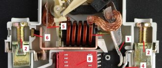
A circuit breaker (circuit breaker) is a device that is installed to protect an electrical circuit from short circuits. This means that the installation of these devices must be carried out exclusively in accordance with the developed project. It is mandatory to test the machines for compliance with the nominal data upon completion of installation operations. During the verification process, the following indicators are identified:
- Rated current.
- Protection trip current.
- Protection response time.
The indicators obtained after checking in accordance with the PUE of circuit breakers are entered into a protocol, which has an approved form.
When should machines be loaded?
To prevent the possibility of a short circuit or overload in the network, it is necessary to load the circuit breakers in the following cases:
- After completion of electrical installation work.
- To assess the condition of equipment after commissioning.
- When there is a suspicion of equipment malfunction.
- After inspection of contacts or emergency situations (especially if a large current has passed through the switch).
- In order to correctly configure the performance of the machines.
Manufacturers indicate the frequency of testing in the passport of each specific type of device.
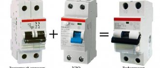
Checking the operation of the RCD with a control lamp
In this case, current leakage is directly created from the circuit, which is protected by the RCD. To carry out the check correctly, you need to understand whether there is a ground in the circuit or whether the residual current device is connected without it.
To assemble the control you will need the light bulb itself, a socket for it and two wires. In essence, a carrying lamp is assembled, but instead of a plug there are exposed wires that can be used to touch the contacts being tested.
Nuances of assembling the control
When assembling the control, two important nuances must be taken into account:
Firstly, the lamp must be powerful enough to create the required leakage current. If a standard RCD with a setting of 30 mA is tested, then there are no problems - even a 10 Watt light bulb will take a current of at least 45 mA from the network (calculated by the formula I=P/U => 10/220=0.045).
Calculation of control resistance
Ohm's law will help you calculate the required resistance - R=U/I. If you take a 100 Watt light bulb to test a residual current device with a setting of 30 mA, then the calculation procedure is as follows:
- The voltage in the network is measured (for calculations a nominal value of 220 Volts is taken, but in practice plus or minus 10 volts can play a role).
- The total resistance of the circuit at a voltage of 220 Volts and a current of 30 mA will be 220/0.03≈7333 Ohm.
- With a power of 100 watts, the light bulb (on a 220 volt network) will have a current of 450 mA, which means its resistance is 220/0.45≈488 ohms.
- To obtain a leakage current of exactly 30 mA, a resistor with a resistance of 7333-488≈6845 Ohms must be connected in series to the light bulb.
If you take light bulbs of a different power, then you will need different resistors. It is also necessary to take into account the power for which the resistance is designed - if the light bulb is 100 watts, then the resistor must be corresponding - either 1 with a power of 100 watts, or 2 of 50 (but in the second option, the resistors are connected in parallel and their total resistance is calculated using the formula Rtotal = (R1*R2)/(R1+R2)).
To guarantee, after assembling the control, you can connect it to the network through an ammeter and make sure that the required current flows through the circuit with the light bulb and resistor.
Testing an RCD in a grounded network
If the wiring is laid according to all the rules - using grounding, then here you can check each outlet separately. To do this, the voltage indicator determines which terminal of the socket the phase is connected to, and one of the test probes is inserted into it. The second probe must touch the grounding contact and the protective shutdown device should operate, since the current from the phase went to grounding and did not return through zero.
In this case, additional checks are required and if grounding testing is a separate topic, then checking the RCD can be performed directly in the following way.
Testing an RCD in a single-phase network without grounding
To a correctly connected residual current device, the wires from the distribution panel come to the upper terminals, and to the protected devices they leave from the lower ones.
In order for the device to decide that a leak has occurred, you need to touch the lower terminal with one control probe, from which the phase leaves the RCD, and with the other probe touch the upper zero terminal (to which zero comes from the distribution panel). In this case, by analogy with a battery test, the current will flow through only one winding and the RCD must decide that a leak is occurring and open the contacts. If this does not happen, then the device is faulty.
Cost of loading circuit breakers in Moscow
Installation of electrical installations requires acceptance and delivery work, which will allow it to be put into operation and used for its intended purpose. When planning to install circuit breakers, you should turn to professionals who can install circuit breakers at a reasonable price in a short time. The electrical laboratory "EnergoServiceGarant" is ready to offer you the services of specialized specialists who will carry out all the necessary tests in Moscow in accordance with regulatory technical documentation. After completing the work, we will provide the client with an inspection report, based on which you can safely use electrical equipment and prevent short circuits or overloading of the electrical network in the future. To order services, fill out the form or request a call back on the website.
Description
The stand can be used when carrying out research and experimental work on the development of new equipment under load , including assessing the energy efficiency of the equipment under test, assessing the quality of various harmonic suppression devices in networks, etc.
The test stand is certified by VNIIM im. D.I. Mendeleev" in accordance with the requirements of GOST R 8.568-97 (certificate No. 207/40-VNIIM-18 dated November 16, 2018) for testing semiconductor frequency converters in accordance with GOST 26567-85 and low-voltage complete devices in accordance with GOST R 51321.1-2007.
An automated test bench for stations and control cabinets with frequency converters allows
- temperature control of the condition of equipment and its components when operating in a wide range of motor loads at ambient temperatures up to +50°C
- change in input voltage from 50 to 125% Un and frequency from 48 to 62 Hz
- simultaneous measurement of electrical parameters at the input and output of the control station with an inverter, including harmonic composition (up to 500 harmonics), voltage and current nonlinear distortion factors, measurement of efficiency, power factor, etc.
Functions of the automated test bench control system
- continuous measurement of operating parameters of the bench equipment and equipment under test, including parameters of supply voltage, load, temperature at controlled points (20 points)
- automatic (according to a given program) and remote (manual) control of electrical equipment of the test bench
- generation and presentation of operational and accounting information on the testing process, including maintaining a log of measurements of all parameters with saving in the database
- generating a test report and saving it in the database
Device for loading circuit breakers
Loading circuit breakers or any other automatic devices is testing the necessary operating parameters of a technical device, which is accompanied by modeling of the installation circuits.
Such services are carried out by trained specialists working in electrical laboratories, using all necessary equipment.
Our specialists have extensive experience (at least 5 years) and high qualifications. EnergoServiceGarant employees carry out their work using proven methods. Contact us and your devices will be guaranteed to be safe.
Specifications.
UPTR of all models consist of the following blocks: Regulating and measuring in one housing and load in the other. The control unit contains a voltage regulator (RN), a synchronization circuit for the supply of measuring current (CC) and a measuring complex (SI). The load block contains load (VT) and measuring transformers (CT).
Supply voltage: UPTR-1MC - 220V, 2MC - 380 V , UPTR-3MC - 380 V.
The maximum duration of the generated current at the main outputs Ш1-Ш2.
Table 1.
| Current range, A | Manual control, sec. | Automatic control, sec. | ||||
| UPTR-1MC | UPTR-2MC | UPTR-3MC | UPTR-1MC | UPTR-2MC | UPTR-3MC | All models |
| 500 | 1000 | 2500 | 7200 | 7200 | 2600 | 0,2 (0,5) |
| 1000 | 2000 | 5000 | 500 | 900 | 300 | 0,2 (0,5) |
| 1500 | 3000 | 10000 | 180 | 180 | 50 | 0,2 (0,5) |
| 2000 | 4000 | 18750 | 90 | 50 | 7 | 0,2 (0,5) |
| 3750 | 10500 | 20000 | 30 | 10 | 3 | 0,2 (0,5) |
| 5000 | 14000 | 25000 | — | — | — | 0,2 (0,5) |
Current mode
- manual – long-term (defined by the operator),
- automatic – 200 ms, 500 ms
Maximum duration of the generated current at additional outputs Kl1-Kl2 for all UPTR models.
Table 2.
| Current range, A | Manual control, sec. | Automatic control, sec. |
| 8…80 | 420 | 0,2 (0,5) |
| 80…100 | 300 | 0,2 (0,5) |
| 100…150 | 120 | 0,2 (0,5) |
| 150…200 | — | 0,2 (0,5) |
The given measurement error under operating conditions is no more than 5%, both for the current meter and for the time meter.
Overall dimensions of blocks.
| Load block, mm | |
| UPTR-1MC | 280x210x190 |
| UPTR-2MC | 260x220x230 |
| UPTR-3MC | 400x320x330 |
| Adjustment block, mm | |
| UPTR-1MC | 380x240x170 |
| UPTR-2MC | 420x240x210 |
| UPTR-3MC | 420x240x210 |
When is it necessary to load circuit breakers?
Monitoring the serviceability of machines is a necessity, according to regulatory requirements. to check circuit breaker loading device in the following situations:
- If the development of the device has been completed and certification has been passed;
- If you have just started using the device;
- If a preventive and scheduled inspection of the device is carried out;
- If various types of repair work have been performed on the device.
Loading devices
To load circuit breakers using primary current, loading devices are usually used. Now there are many such devices that differ in certain characteristics depending on the types and rated currents.
A generalized diagram of a simple loading device includes:
- laboratory autotransformer (LATR)
- control key (KU)
- load transformer (LT)
- ammeter with different measurement limits (shunt)
- current transformer (CT)
- connecting wires
- stopwatch
EuroSMC products
The most popular model at the moment is the innovative multifunctional primary current loading complex RAPTOR. The RAPTOR current loading complex is a high-precision, simple and easy-to-use testing system for testing substation equipment. RAPTOR has the widest application: from loading with primary current to measuring the resistance of switch contacts. By replacing several devices, RAPTOR thereby saves time and material costs. The RAPTOR current loading system consists of a RAPTOR HH control module and a RAPTOR MS power module. The modular design of RAPTOR allows the end user to expand the existing configuration at any time. You can get detailed information on the EuroSMC website dedicated to the RAPTOR current loading system: smcraptor.com