When turning on powerful three-phase electric motors and outdoor lamps, special power relays are used - electromagnetic starters. Among the wide variety of varieties of such devices, the PML brand models were the first to appear. What these devices are, what they are made of, what they are used for and how they are connected will be discussed in this article.
Magnetic starter PML
Electromagnetic contactors (starters)
We need to bring some order to the terminology.
Starters and contactors are often confused. To some they are the same thing, and some say that a contactor is just a big, powerful starter. But no one can really explain how powerful it is... Previously, during the times of the USSR, this was the case. Now starters that were produced or developed in those days are called starters (for example, PML, which is still produced in Ukraine), and new and foreign models are called contactors.
Electricians call the same devices starters, and sellers call them contactors. To be honest, I’m more used to talking about starters.
History of creation
This device was designed in the middle of the twentieth century by the French company Schneider-Electric. The invention, which became a real breakthrough in the field of automation, quickly became popular. Such an electromagnetic switch was in great demand at that time in the USSR, whose government subsequently bought a patent for its design from Schneider-Electric and quickly launched production of domestic starters. Many of those models produced in Soviet times can still be found in some plants and factories. Assembled from high-quality components, although they are more bulky and less aesthetically pleasing than modern analogues, they significantly outperform the latter in reliability and durability.
Safety and reliability
We set a goal: to create not only affordable, but also the most reliable and safe devices for solving a wide variety of household and industrial problems. It was important to achieve a balance of high quality and safety. This balance was achieved through a number of solutions we applied:
- — mechanical connection of contacts and additional mirror contacts for precise control of the starter state;
- — self-cleaning of contacts due to the use of additional contacts with corrugation and a sliding effect;
- — protection of terminals from direct contact with current-carrying elements;
- — continuous feedback from programmed controllers and microprocessors;
- — informing about the degree of wear of power contacts.
TeSys starters can withstand more than 1 million switching cycles, they are immune to shock and vibration, and do not make noise during operation. Schneider Electric equipment is indispensable equipment for any modern facility with high requirements for quality, reliability and efficiency at a reasonable price.
RESULTS
RESPONSIBILITY, RESPONSIBILITY, REPORT °ÑÑ Ð¿Ð¾ Ð¾Ð´Ð½Ð¾Ð¼Ñ Ð¿ÑинÑипÑ. RESULTS ? ROOM smear Ñное поле, ÑиловÑе линии коÑоÑого з RESULTS RÐ, S. е. Sorry. ROOM µÐ³Ð´Ð° иÑпÑÑÑваÑÑ ÑÑÑемление ÑокѰÑиÑÑÑÑ Ð¿ ROOM ¼Ð°Ð³Ð½Ð¸Ñоп²Ð¾Ð²Ð¾Ð´Ð° RESULTS ROOM RESULTS 1/2 аÑÑÑÑ Ð²Ð½Ð¸Ð· и з registry ºÑÑ Ð² нижней ÑаÑÑи ÐÐ. RESULTS RESULTS.
" RESULTS RESULTS ли в блоке конÑакÑов. RESULTS RESULTS registry, registry же дополниÑелÑнÑе конÑакÑÑÑазмѺаÑÑÑÑ.
Main product advantages
The magnetic contactor from Schneider Electric has a number of advantages in comparison with analogues:
- — operating temperature range is above average – from -50 to +50 degrees Celsius;
- — extended range of rated current;
- — simplified installation thanks to special screwless clamps;
- — low noise during switching;
- — resistance to shock and vibration;
- — economical energy consumption;
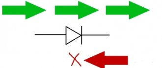
- — the contactor additionally protects against voltage surges thanks to the built-in Transil diode;
- - increased durability and wear resistance, which is determined by the use of innovative developments.
RESPONSIBILITY: RESPONSIBILITY
RESULTS, ASSURANCE, RESPONSE RESULTS SUBJECT: SUBJECT Ñ "ROSS" "SÑS. RESULTS ASSURANCE, ASSURANCE, ASSURANCE "R" RESULTS RESULTS ROOM ROCK, S. е. RESULTS .
ROOM ROOM ROOM ROOM ROOM ›› ÑепловÑм ÑаÑÑепиÑелем. RESULTS RESULTS ¾Ð²Ð° RESULTS RESULTS, RESULTS, ASSURANCE Ñи ÑлиÑком RESULTS
RESULTS каÑÑки пк ¿ÑекÑаÑаеÑÑÑ, его конÑакÑÑ ÑазмѺаÑÑÑ Ð¸ двиР³Ð°ÑеÐ"Ñ Ð¾ÑкÐ"ÑÑаеÑÑÑ.
Schneider Electric contactors: TeSys D and TeSys K series
TeSys D series
The series includes both reversible and non-reversible models, with different control circuit options. Suitable for all types of starters, connection - screw and spring terminals, terminal, cable with lugs, busbars or plug-in contacts. Each element is compatible with the manufacturer's latest patented technologies to ensure maximum engine protection, ease of installation and long-lasting installation. This type can be used as a contactor, motor starter, used in construction or organizing production infrastructure.
TeSys F series
The small dimensions of the devices in this series can provide a manifold increase in the efficiency of the working or operational process. This device with an automated switch will well complement the electronic relay contactor of this series, ensuring quick start-up and maximum engine protection. The TeSys F line equipment is safe and versatile in operation:
- — control circuits – alternating or direct current;
- — universal connection in various ways;
- — areas of application in addition to standard ones — control of engine operation;
- - any type in any operating conditions.
TeSys K series
Another compact modular contactor designed for three-phase motors. Significantly saves working space during installation and further operation; it can also be used as a starter contactor for electrical installations with low power consumption, susceptible to interference and voltage surges. Mounting method - on rails or screws, complete absence of noise during operation, control circuits - alternating or direct current, coils with reduced power consumption.
Areas of use:
- — residential or office premises;
- — industrial enterprises;
- — infrastructure.
TeSys B series
There is also a relay contactor of the TeSys B series. This is a rack vacuum contactor, available in four different models, the control circuit in this case is alternating current, rail mounted, designed to optimize the operation of motors of any type, capacitive and inductive connection circuits, circuits with active resistance .
This equipment is used in:
- — construction;
- - industry;
- — infrastructure;
- - in office and residential premises.
What is the difference between a contactor and a starter?
In fact, a contactor is a device consisting only of an electromagnetic coil and contacts. When voltage is applied to the coil, the contacts close (or open). The contactor does not contain devices for protection, fixation, switching, indication, etc. A starter is a device that contains a contactor as the main component element. In addition, the starter usually contains a thermal relay for protection against overcurrent, START and STOP buttons, an indication, can be enclosed in a housing, and have a circuit breaker for short-circuit protection. In other words, the starter is used to start (turn on) various electricity consumers.
The starter can contain two contactors. This happens in cases where reverse engine control is used, or during a soft start, when a powerful engine is turned on first in a star circuit and then in a delta circuit.
Disassembled starter PML-1220 0*2B. The contactor and thermal relay are visible.
Differences between a relay and a contactor
Relays differ from contactors only in design and purpose, and the difference between them is sometimes barely distinguishable.
Usually,
- The relay does not have arc chutes.
- The relay is housed in a sealed housing.
- The relay is designed for low current and purely resistive loads.
- The relay has switching contacts, which means normally open and closed.
- The relay is not designed to connect a reactive three-phase load.
- A relay can have from 1 to 6 equivalent contacts, and a contactor must have 3 power and (as an option) 1-2 low-current contacts.
- The relay does not have additional functions or contacts, and the contactor can be supplemented with attachments for various installations and purposes.
- The relay is mounted on the panel and can be easily replaced using just your hands. In order to replace the contactor, you need to de-energize the equipment and use a screwdriver.
Errors in selection
Some people mistakenly look first at the arc chutes, thinking that if they are there, then there is a contactor in front of them.
Allegedly, they are needed to dampen currents, starting from the 5th magnitude. The fifth value is a current equal to I=100A.
At the same time, thinking that the starter is designed only for low currents (up to 100A).
Supporters of this classification even came up with their own gradation:
relays are devices for low currents
starters – for medium
contactors – for high currents
All this is of course not true. One fairly popular brand, namely PML, is most likely to blame for such misconceptions.
For these models, starters are designed for currents from 10 to 100A, and contactors from 10 to 800A. This is where the confusion started.
Allegedly, if the device is more than 100A, then it belongs to the contactors. Some packages even contain seemingly opposite messages. On one side it says:
PM – magnetic starter
And then on the other:
Contactor
What should we believe and what do the rules and documentation say about this? To understand this, first of all, let’s find the definitions of these devices and see what the differences are.
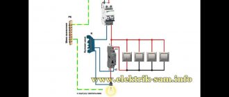
Installation of starters
Electromagnetic contactors are installed in two ways: on a DIN rail or using durable galvanized bolts.
Mounting equipment on a DIN rail
The contactors are mounted on a DIN rail thanks to the presence of a special groove with a retractable stopper on the back of the base. In order to fix the starter, the groove stopper is pulled out to the end, the device is put on a metal or plastic rail 35 mm wide, after which the stopper is returned to its original position. A starter secured in this way can, if necessary, be quickly dismantled and replaced with a new one.
DIN rail
Bolting
The contactor is secured using bolts as follows:
- Several holes are drilled in the panel on which the device is planned to be mounted;
- Using a tap, an internal thread of the required diameter is cut into the drilled holes;
- The bolts are inserted into the holes on the starter body and screwed into the cut threads on the panel.
Compared to a DIN rail, this installation method is more reliable, but it also requires significantly more time and effort.
Options
The main parameters of such devices include:
- Switching wear resistance is a characteristic indicating the maximum number of on/off cycles the device can withstand without repairing or replacing contacts;
- Number and type of contacts;
- Rated current for which the device contacts are designed;
- Voltage supplied to the control coil;
- Degree of protection (IP) from moisture and dust;
- Availability of control buttons, signal lamp;
- Availability of reverse function and built-in thermal relay;
- Dimensions and weight;
- Type of fastening (on DIN rail, using screws or bolts).
On a note. The main characteristics of the starter can be found by deciphering its markings.
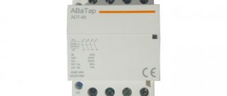
Purpose and features of small-sized contactors
Frequent changes in current in electrical networks when turning electrical equipment on and off leads to emergency situations. To prevent them, a KMI contactor is used, which operates remotely under the control of weak electric currents. The name stands for small contactor. The device is also known as a KME contactor, that is, electromagnetic. It closes and opens electrical circuits that are in normal mode. These devices do not protect against short circuits, like automatic machines, but only carry out a combination of rated currents on different lines.
The small-sized KMI contactor is designed for a current load in the range of 9-95 A. Basically, these are asynchronous electric motors with a squirrel-cage rotor, as well as various types of loads with low inductance. Devices operating with a current load of up to 40 A are equipped with one group of make-break contacts. For currents above 40 A, two separate contact groups are installed - making and breaking.
These devices switch three-phase capacitor banks, as well as primary windings in three-phase low-voltage transformers. Exactly the same functions are performed by the small-sized KME - electromagnetic contactor.
Equipment of this type has undoubted advantages:
- The KMI - IEK series is produced in a wide range, significantly exceeding the number of analogues on the domestic market of electrical appliances.
- Together with contactors there are a large number of additional devices - contact attachments, electrothermal relays, time delay attachments and other useful equipment. They protect the electric motor from maximum current overloads, phase distortions and asymmetry, prolonged starting and rotor jamming.
- All KMI-IEK devices can be easily installed on a DIN rail with a width of 35 mm, unlike domestic products, for which such fasteners are installed only upon request.
- KMI-IEK devices allow reverse operation using a special locking mechanism.
- The design of the cover allows you to install additional contacts using a special attachment.
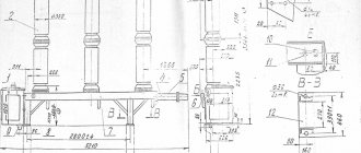
Conditions for installation and placement of PMA starters.
Installation is carried out on a vertical surface using mounting screws, with an inclination of no more than 15 degrees. The altitude above sea level is not more than 2000 meters (when placed at an altitude from 2000 meters to 4300 meters, the rated current of the starter is reduced by 10%). PMA starters are installed in rooms with a non-explosive environment in which there are no aggressive gases in concentrations that can lead to destruction of the structure.
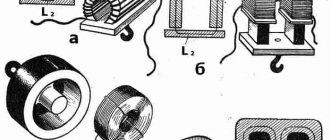
Design features.
Depending on the values, starters have different designs. For example, contactors of 3rd magnitude starters have a linear W-shaped magnetic system. This system consists of an armature and a core, which are housed in a plastic housing. Contactors of starters of the 4th, 5th, 6th magnitude have a different magnetic system - a forward-running U-shaped magnetic system. If a thermal relay is used together with the starter, then it is attached to the starter using a special square.
Decoding
- PMA series designation
- 3 - designation of rated current 40A
- Designation of starters based on the presence of a thermal relay and reversing design: 1 starter without a non-reversing relay
- 2 irreversible types with thermal relay
- 3 without thermal relay, reversible type
- 4 with reversible thermal relay
- 0 IP 00 without protective shell
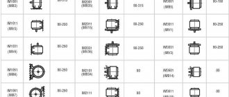
Overall and installation dimensions
PME
| Figure 1. PME series irreversible starter with relay | Figure 2. PME series reversible starter with relay | ||||||
| Figure 3. PME series starter in a protective housing | |||||||
| Starter type | Drawing | L, mm | H, mm | B1, mm | B2, mm | A1, mm | A2, mm |
| PME-211 UHL4 V | 1 | 89 | 116 | 93 | — | 75 | 75 |
| PME-212 UHL4 V | 170 | ||||||
| PME-213 UHL4 V | 2 | 200 | 130 | 130 | — | 170 | 100 |
| PME-214 UHL4 V | 170 | ||||||
| PME-221 U3 V | 3 | 150 | 154 | 222 | — | 100 | 150 |
| PME-222 U3 V | — |
Areas of use
Among the leaders in the production of safety electrical equipment and automation equipment, Schneider Electric is deservedly considered one of the most reliable and progressive. Modular contactors are widely used in industrial production, trade and in everyday life.
This type of electrical equipment is most in demand for energy supply and installation:
- — ventilation and air conditioning systems;
- — lighting systems;
- — valves;
- — automatic gates, doors, etc.
All magnetic contactors can be divided into two categories, differing in their design features and capabilities:
- - reversible;
- - irreversible.
Structural elements
Each KMI contactor is equipped with a coil or electromagnet, which forms the basis of the device. This component is powered over a wide voltage range - 12-380 volts. Before connecting, you need to accurately set the operating current of the electromagnet, indicated in the passport or on the side of the coil body.
The next important design element is the core. It is a prefabricated structure with metal plates impregnated with varnish. The core consists of fixed and moving parts. The first part is used to accommodate the coil, and the other part - the movable one - is intended to accommodate the movable contacts. The fixed contacts are secured using screws to the plastic body of the device. Movable – attached to the core with a special insulating holder. Short-circuited aluminum rings are pressed into the pole tips of the stationary part, eliminating the effect of detonation.
The contact area of the contact solders in different IEC designs may differ. It depends on the operating current of the power circuits, which can be passed by the contactor. In this regard, each type of device has its own value - first, second, third, etc. Most of them are equipped with four contact pairs: three are intended for the power circuit, and one is additional and performs various functions. It blocks the control circuit, turns on a sound or color alarm, and partially provides automatic relay protection for the control of electrical installations.
The conductors are connected using special connecting contacts. They have an oval shape, which increases the reliability of fixation. For small wires, hardened disc washers are used, and for large conductors, a clamping clamp is provided. Notches on the contacts further increase the reliability of fixation, increase the contact area and reduce heating of the wires.
When power is applied to the coil, it results in an electromagnetic effect. Under its influence, the metal cylinder begins to move upward, after which the contact closes. The circuit supplying power to the coil is considered the control circuit, and the voltage in it is quite low, within 24 volts. The other circuit that closes the contact is a power circuit, since a current with a voltage of up to 660 volts passes through it. In the absence of power supply, the metal core returns to its original position under the action of a spring, and the circuit is open.
Rules of care
In order to maintain a magnetic starter in appropriate conditions, you need to be well aware of all the faults that such a unit most often encounters. This concerns a sharp increase in the temperature of parts and strong humming of the equipment.
Overheating is mainly associated with inter-turn short circuits of the coil, and in this case it is impossible to do without replacing it. Heating of parts can occur due to increased voltage in the electrical network.
A strong hum from the unit is observed in many cases. Among the main reasons is poor fit of the armature to the core due to contamination or damage to their surface. Other factors include jamming of the moving part and a decrease in the rated voltage in the network (by 15% or more).
Negative consequences can only be avoided with timely care. The huge advantage is that such a unit does not require expensive maintenance. The technician just needs to prevent dirt, dust and moisture from getting into the device. The tightness of the clamps and the condition of the contacts must be checked regularly. In addition, you can resort to a certain list of measures often used by electrical engineers.
Design
Structurally, the electromagnetic contactor consists of two main blocks:
- Bottom (base) - this block consists of a cover, inside of which there is an W-shaped fixed magnetic circuit with a control coil in the central part. The number of turns and dimensions of the control coil depend on the voltage applied to it. Thus, in Soviet and modern models of these devices, coils designed for voltages from 24 to 380 V can be installed.
- Upper (contact group) - this block includes two types of contacts: movable and fixed. Spring-loaded movable contacts are located on a traverse with a fixed magnetic circuit (core) having the same shape and dimensions as that installed in the base. In this case, the cores of the base and contact group, identical in shape and size, are located opposite each other.
Two groups of fixed contacts are located on both sides of the movable traverse and secured in special grooves with screws. One group of such contacts is supplied with power cables that are under the voltage required to power the load. The second group of contacts is connected to the operating circuit - the cables that power the load.
Since sparking often occurs when connecting relay contacts, the entire upper part of the device is covered with a special cover that acts as a spark arrester.
PML contactor design
Between the upper and lower blocks there is a return coil or leaf spring.
On a note. For safety and more convenient control of the device, it is often placed in a sealed case with two buttons: “Start” and “Stop”. Some models often have a third button – “Reverse”.
Operating principle
This multi-contact electromagnetic relay works as follows:
- Using a button, an electric current with a specified voltage is supplied to the control coil;
- The current passing through the turns of the coil leads to magnetization of the W-shaped fixed core of the base;
- The magnetized lower fixed core attracts the magnetic circuit located on the movable cross-arm, compressing the elastic return spring;
- As a result of the attraction of the traverse core to the base magnetic circuit, it is closed by the spring-loaded fixed power contacts;
- As a result of the pairwise closure of the movable contacts of the traverse of the fixed power contacts, the load is switched on.
Magnetic starter PME-211
The starter and, accordingly, the load connected to it are switched off when the supply of electric current to the control coil is stopped: the lower core is demagnetized and ceases to attract the upper one, as a result of which the traverse with contacts under the action of an expanding elastic spring disconnects the power contacts.
On a note. Under normal conditions, a working starter makes clicking sounds of the same duration when turned on and off. If the device makes different sounds, then there may be various malfunctions of its internal components.
Technical characteristics and types of KMI
The standard KMI contactor is an alternating current electromagnetic device that provides switching of electrical installations and equipment with power circuits.
Each model has the symbol KMI-Х-ХХ-Х-Х, which is deciphered as follows:
- The first character X means operating current limits, which are 1-9, 12, 12 A, 2-25, 32 A, 3-40, 50 A, 4-65, 80, 95 A and correspond to specific groups of devices.
- The second symbol XX corresponds to the rated current of category AC-3 and means several groups of small-sized starters. 1st group - 9, 12 and 18 A, 2nd group - 25 and 32 A, 3rd group - 40 and 50 A, 4th group - 65, 80 and 95 A.
- The third character X indicates the specific configuration of the contactor. For example, the number 1 corresponds to a device without a shell and without reverse.
- The fourth X character indicates the number of additional contacts. The number 0 is 1 normally open contact, the number 1 is 1 normally closed contact. The number 2 corresponds to the 1st make and 1st break contact.
The main parameters and technical characteristics include the following:
- The rated operating voltage is 230, 400 and 660 volts.
- The rated insulation voltage is 660 V.
- The rated pulse voltage is 6 kV.
- Rated operating current – 9-95 A.
- The value of the conventional thermal current is from 25 to 125 A.
- Indicators of maximum short-term load for less than 1 s for different devices range from 162 to 1710 A.
There are other device characteristics specified in the technical documentation that should be taken into account when choosing a product.
The manufacturer IEK produces a wide range of devices with different parameters and the possibility of use in various electrical circuits. Among them, three main groups can be noted:
- Small-sized AC IEC devices 9-95 A. Used for remote control of various industrial electrical installations, in lighting systems, etc.
- The contactor is a small-sized KMI with a thermal lever in its design. It is placed in a metal or plastic case and is used for switching three-phase motors operating with voltages up to 400 volts. If any phase is broken and overloads occur, this device is triggered and protects the circuit.
- KMI contactor, which has a coil that controls direct current. Used in automatic transfer systems, at power plants and distribution points, in electrical networks of railways and subways. There is no inrush operating current in the control coil.
ROOM
Ð ÑÑой ÑеÑии вÑпÑÑкаÑÑÑÑ Ð´Ð²ÑÑ Ð²ÐµÐ»Ð¸Ñин: 1-й Ñ ÑÐ ¾ÐºÐ¾Ð¼ главнÑÑ ÐºÐ¾Ð½ÑакÑов до 10 Ри 2-й â до 25 R. RESEARCH, RESEARCH, RESEARCH Ò 1 (ratio), 2 (ratio ½ÐµÐ½Ð¸Ðµ) и 3 е) â в завиÑимоÑÑи Ð¾Ñ ÑÑепени заÑÐ¸Ñ Ð¾Ñ Ð²Ð½ÐµÑÐ ½Ð¸Ñ ÑакÑоÑов. ROOM, ROOM, ROOM ratio 2 Ñ 3=6.
RESULTS ¿Ð»ÐµÐºÑованноÑÑÑÑлекÑÑоÑепловÑм Ñеле (ÐТР) да SÑÑ ÐµÑе ÑеÑÑÑе моди RESULTS: 1 â без ÑевеÑÑа и без ТР, 2 â без ÑевеÑÑа, но Ñ ÐТР, â Ñ Ñ ÑевеÑÑом но без Ð 4 â Ñ ÑевеÑÑом и Ñ ÐТР. value 6Ñ4 = 24 value ¸ÐºÐ°Ñии ÐÐ SÑеÑии ÐÐÐ.
211 10 years ago ±ÐµÐ· ÑевеÑÑа и ТР.
Contactor capabilities
Three-pole electromagnetic AC contactors are the most popular. The principle of operation is simple: a certain voltage is transmitted to the coil from the power source, after which it begins to turn on and off power contacts at short intervals. This technology eliminates surges and uncontrolled increases in voltage, reduces the duration of the arc, and protects power contact blocks from premature failure even during intensive use.
Contactors are aimed at automating the switching of electrical circuits and at the safe control of asynchronous equipment. Thanks to proven components, it becomes possible to build an extensive automated control system and at the same time ensure maximum safety.