Before proceeding with the installation of circuit breakers, it is necessary to determine the operating conditions of the electrical network with its characteristics:
- By current;
- By voltage;
- Electrical power of devices that will be connected as a load.
The type and characteristics of the selected circuit breaker, and, accordingly, the methods of its installation and connection depend on this.
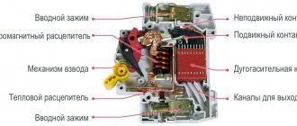
In most cases, circuit breakers are installed in distribution cabinets, before the network enters a specific facility with equipment that is used as a load. To properly install a circuit breaker, you need to understand how it works, what processes occur during operation, and know the design features of various types.
Purpose and scope of circuit breakers
Circuit breakers are control elements of the switching system and perform three main functions:
- Conventional switch, on and off;
- Disconnecting the load from the network when the set current threshold is sharply exceeded, this happens when there is a short circuit in the circuit or a malfunction of the load equipment;
- Some circuit breakers trip when the current suddenly drops when appliances that consume large amounts of electricity are turned on. To eliminate malfunctions on expensive equipment during large surges in voltage and current in the network, the machines switch off the load.
All these machines have different technical characteristics and design features.
Main types of circuit breakers
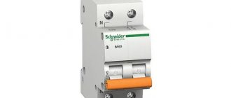
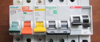
Manufacturers make many varieties of different models, despite their design differences.
Appearance of different types of circuit breakers They all work on the same principle and are designed for the same purpose. When the set current threshold is exceeded, they disconnect the circuit from the power source to protect the equipment from overloads.
Based on their purpose, circuit breakers can be divided into the following types::
- For switching equipment in lighting, socket networks, power lines with household equipment of low power;
- For switching power supplies to electrical installations that are operated in extreme conditions, in explosive environments, high humidity or dust;
- For repeated switching of semiconductor devices in various electronic systems.
Based on design features, they are divided into three main types.:
- Air switches have holes in the housing design through which the elements inside are ventilated. Such models are used in normal dry operating conditions, without fumes and dust;
- Switches with molded housings are used in extreme operating conditions;
- Modular switches are one of the air switches; the design feature is that their dimensions and fastening mechanism are standardized.
The latter option is in greatest demand among consumers at the domestic and industrial level. The reason for this popularity is the versatility of these models, ease of installation and connection. Therefore, we will look in detail at how these circuit breakers are connected.
Industrial or homemade shield?
Nowadays different shields are sold. All kinds of shapes and sizes. They have either a primed metal, painted base or a plastic base. There are also brushes with internal factory filling. There are designs available for individual order.
But, if the shield installer has certain skills, then it is better to install the internal parts yourself, at your own discretion. The more experience, the more competently the installation of the structure in a certain volume of the electrical panel will be completed.
Characteristics and selection criteria for modular circuit breaker
When choosing a modular circuit breaker, the following characteristics must first be taken into account:
- The maximum breaking capacity is measured in kA (kiloAmperes) - this is the current value at which the circuit breaker still remains operational. The minimum value of this parameter on industrial and household networks is from 3 kA to 10 kA;
- Time is a current characteristic , sometimes this value is called the sensitivity of a circuit breaker to current overloads.
| Sensitivity class | Rated contact tripping current |
| B | 3-5 from In X 10; |
| C | 5-10 from InX10; |
| D | 10-50 from InX10. |
In terms of sensitivity, the switches have three classes, B - the circuit breaker is switched off when the rated current is 3-5 times higher than the rated current for a certain section of the network. C – 5-10 times and D 10 – 20 times; when operating equipment with electric motors, option group B is not recommended; short-term starting currents can cause unreasonable, frequent shutdowns. is considered to be C, for electric motors D.
Recommended loads for machines with different sensitivity categories
| B | for networks with small short-circuit currents (heating elements, stoves); |
| C | for sections of the network with high currents, the most popular; |
| D | with high starting currents (welding, asynchronous electric motors, transformers) |
- The rated current of the network section when a shutdown occurs, switches are manufactured with values in the range of 0.5 - 125 A for modular designs. For industrial input circuit breakers, this value can reach thousands of Amperes.
- The number of poles on the switch can be from 1 to 4. The width of the housing of a single module, depending on the product series, is 18 mm, the compact version is half less than 9 mm, the extended version is 27 mm.
Taking these parameters into account, a selection of switches is made for a specific section of the network, after which a diagram of their connection is drawn up or studied.
Circuit breaker connection diagrams
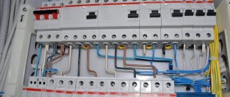
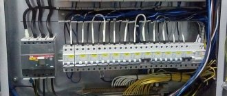
The classic option is to include automatic modular switches in the network circuit by placing them in a distribution board. Fastening is carried out on a factory din-rail located horizontally inside the shield. Wires leading to the load are inserted into the space between the rail and the rear wall of the cabinet. They are connected to the lower output contacts of the machines, and the wire from the output of the input machine is connected to the input, upper contacts.
DIN rail mounting of circuit breakers is considered the simplest and most effective technology today.
A channel is made on the back wall of the machine for the rail, the upper edge of the case clings to the rail and by pressing on the front plane of the case, a lever with a spring fixes the lower part of the case to the rail. The machine is removed from the rack in the reverse order, the lever is pulled back, the lower part of the body is retracted, lifting it up, thus the entire body is removed from the rack.
Tip No. 1 High-power input circuit breakers that are not equipped with DIN-rail mounting are separately mounted on a metal plate installed in the panel with holes and threads for bolts. Holes in the machine body for fastening to the shield body are provided by the design; metal screws can be used.
Single-pole circuit breakers
Connecting single-pole circuit breakers is considered the simplest; they are connected to socket and lighting groups.
The phase wire, grounding and neutral conductors are connected through the circuit breaker; they pass directly to lighting fixtures and sockets.
Two-pole machines
More powerful devices, such as electric stoves, heating boilers, shower cabins, split systems and others, where it is necessary to ensure a complete circuit break, neutral and phase wires are connected through two-pole devices.
Three-pole circuit breakers are used in three-phase networks using powerful devices with an appropriate 380V power supply. These can be heating elements, electric motors and others. When, when the rated current is exceeded, all three phases are disconnected, thus eliminating phase imbalance in the entire circuit when the current is exceeded in one of the three lines.
The load is connected to the circuit breaker according to a star circuit without a neutral wire; in this case, the circuit breaker is installed individually for a specific type of equipment.
Four-pole circuit breakers are connected to a three-phase network as input circuit breakers, where the phases are used as separate network lines with individual load elements. In this case, it is necessary to try to distribute the magnitude of the load currents evenly among the phases to avoid phase imbalance. To remove excess currents, a neutral wire is used, a circuit with a grounded neutral.
Why does it “close”?
Let's look at what kind of protection elements are on the shield. Often there are only two archaic fuses on it, for some reason called “plugs”. They burn out over and over again when the load on the network increases and require replacing the inserts in them. Energy experts say that the ancient home network was designed for a power of up to three to five kilowatts in a Khrushchev. And there was nothing to exceed it.
Today, up to 15 kilowatts are designed for each citizen of the Russian Federation, but this does not mean that for a family of three, the electrical wiring must withstand 45 kW. Perhaps new buildings have such powerful networks.
But only an electric iron gains up to two kilowatts, almost the same as a boiler for heating water, if there is no such centralized service. There is also an electric stove, a refrigerator, a washing machine, and in the country house there is a well with electric water pumping.
How can you protect your home and yourself from hot electrical wiring and fire? Turn them on one by one, or what? Below are the answers to them and instructions on how to connect the machines in the panel.
Sequence of operations for connecting a circuit breaker
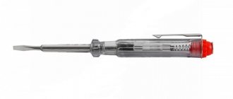
- The section of the network into which the circuit breaker is connected is de-energized by a switch or an input circuit breaker. The presence of voltage is checked with an indicator screwdriver, a multimeter or other indicator device. After this you can start working;
- The circuit breaker is fixed on a DIN rail located in the distribution board;
- From the ends of the wires connected to the switch terminals, the insulation is removed to a depth of 8 mm to 1 cm.
Tip #2. It is necessary to strip the insulation to the depth of the contact terminal, as far as the end of the wire is immersed there; the exposed wires should not protrude beyond the switch body. Anything less is also not recommended; the clamping screw may rest against the insulating layer and the contact area will not be sufficient to ensure reliable contact. In this case, the connection will heat up and the machine will fail.
- In the two-pole model of the switch, the neutral and phase wires are connected to the terminals of the corresponding designation on the upper contacts;
- The phase and neutral wires going to the load are connected to the lower output terminals;
- The wires in the contact sockets are tightened with bolt clamps;
- After the connection, you can connect the power and check the functionality of the switch.
Machines with a different number of poles are connected in a similar way.
Blog
Attention! My post is primarily informational in nature and not a call to action. Perhaps it will be of interest to electricians who have not yet performed such work. I do NOT advise ordinary “mortals” to climb into the shield. LIFE THREATENING!
Replacement of electric risers and reconstruction of electrical networks in old housing stock is not happening as quickly as we would like, so replacing old machines with new ones remains a very popular service.
If you decide to replace the electrical wiring, run a new line for the washing machine from the switchboard, or simply start an electrical inspection in your apartment, then in any case you will have to go into the floor switchboard and change the old machines.
The process itself is not so complicated, but very dangerous! Any mistake when performing work on the floor panel may result in: a fire on the floor panel, injury or death for the person performing the work, an accident in the electrical network with a blackout for neighbors or the entire entrance. No irony, this is really dangerous!
As a rule, it is not always possible to de-energize the floor panel, and work is carried out under voltage. Therefore, it is better to entrust such work to an adequate electrician who has access and the ability to completely de-energize the floor panel.
Advice
During any electrical installation work in a floor panel, and especially under voltage, the electrician’s protective equipment should be as high as possible!
So, we climb into the old floor panel to replace the machine guns...
Replacing old machines
As an example, I chose one of the complex replacement options - when the machines of two apartments are tied together with one fastener. In such cases, the ideal solution would be to replace not only your own, but also neighboring machines.
But it may happen that your neighbors may be: either a neighbor with paranoia that they will steal her electricity, or a neighbor who is convinced that the quality of automatic machines was better in the USSR, or antisocial elements who will not have money for this “expensive operation." Therefore, we will have to somehow get out of this situation.
The complexity of the work in this case lies in attaching the machines to the metal panel.
If you remove the top and bottom bars, the machines will remain hanging on the wires connected to it. If they are left in limbo, then when turning the machines on or off, there is a huge probability of shorting everything to hell.
It is also impossible to leave the mount as is, it will interfere with the installation of new modular devices.
What should I do? I proceed as follows: I cut the connecting strip in half and fasten only the adjacent machines with it (only for fastening old machines).
You can take a closer look at the photo and see that the fastening bar is very close to the machine's clamping screw. Therefore, I insulate the installed half of the strip using two-color insulating tape (yellow-green).
note
This is done so that the electrician or “non-electrician”, when checking the voltage at the terminals of the machine, does not short-circuit the metal part of the screwdriver to the housing.
This is a fairly common problem, since many people do not know or forget that the metal mount is connected to the shield body.
After we have screwed the lower fastening bar, you can turn off the bag of the required apartment. In old shields it is located immediately under the required machine guns.
The task of the package operator in the floor panel is to turn off the voltage to the electric meter and the apartment's circuit breakers. The connection diagram itself is as follows: switch → meter → machines.
Usually the switch is turned off by turning to the right, but this is not a fact. Such switches can turn left and right, and turn off only after a few turns. It happens in different ways, so after turning, be sure to check the voltage on the circuit breakers you are switching off.
Attention! Before disconnecting the old packager, take a closer look at its contacts and body.
If the contacts are blackened or burnt (usually the wire is exposed at the point of their connection) or there are cracks on the body , then such a bag CANNOT BE TOUCHED! IS IT DANGEROUS! When such a package is disconnected, a short circuit may occur inside between the contacts. Due to the fact that the protection of the floor riser is turned off with a serious delay (and even if it is present, it may even be absent altogether, this happened in my practice), this can lead to a very serious accident, in fact, a powerful explosion can result, dangerous for your health. Therefore, if before disconnecting the packetizer you notice its defects, then you CANNOT disconnect or even touch such a packetizer! In such cases, it is necessary to de-energize the floor switchboard and replace the old packet switch with a new switch.
Common mistakes when connecting circuit breakers
- When connecting two or more pole circuit breakers at the input and output, ensure that the conductors match. The neutral conductor at the input must exit through the same switch module. Accordingly, phase wires should also not be confused; for this purpose, color marking of insulation must be used. The blue wire lays the neutral line, red, black and white phases, all colors at the input and output must match. This is especially important when powering asynchronous motors in three-phase 380V networks using three and four-pole switches. If the phase wires are mixed up, the motor may rotate in the other direction.
- When calculating the required power and rated current in the network, a circuit breaker with standard values upward is selected. If the calculated value of the rated load current is 23 A, then the machine must be set to 25 A. This will eliminate frequent shutdowns due to short-term current surges when the motors start.
RCD at the input and single-pole circuit breakers
Advantages:
- cheapest option
- small shield (up to 32 modules)
Flaws:
- there is practically no grouping of lines
- there is no possibility of changing the load by phase
- there are zero buses
- possible false triggering of RCD
Here, only one RCD is used at the input (except for consumers that cannot be disconnected) and then the load is distributed through single-pole circuits. According to clause 7.1.83 of the PUE, you may be limited in the choice of the number of connected lines.
If you ignore this rule, then false alarms of the RCD are quite likely. At the same time, you will rack your brains for a long time wondering whether it worked as a protection or falsely.
Therefore, it is better to look for intermediate options for completing a three-phase panel.
FAQ
- Where should the input machine be installed, before or after the electricity meter?
A definite answer, up to the meter, in a separate plastic box equipped with a DIN rail for mounting the machine.
The case is closed and sealed by a representative of the energy supply organization; only the switch lever of the machine remains accessible.
Such measures make it possible to de-energize the network if it is necessary to repair or replace the metering unit and the elements that are connected to it.