The selectivity or selectivity of circuit breakers is key to ensuring reliable operation of an electrical circuit. This function helps prevent emergency situations and raises safety to a higher level.
In the event of a line overload or short circuit, only the line with damage is protected, the rest of the electrical installation remains in working condition. We will analyze in detail why this happens in this article, consider the main tasks of selective protection, connection diagrams and their features.
We will also pay attention to the calculation of selectivity and the rules for creating a map, providing the material with visual diagrams, tables and photos. And we will supplement the article with detailed explanations in videos.
The meaning and main tasks of selective protection
Safe operation and stable operation of electrical installations are the tasks assigned to selective protection. It instantly calculates and cuts off the damaged area without interrupting the power supply to healthy areas. Selectivity reduces the load on the installation and reduces the consequences of a short circuit.
With well-functioning operation of circuit breakers, requests for uninterrupted power supply and, as a consequence, the technological process are satisfied to the maximum.
When the automatic equipment that carries out the opening becomes faulty as a result of a short circuit, thanks to selectivity, consumers will receive normal power.
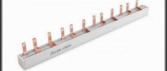
The rule stating that the amount of current passing through all distribution switches installed behind the input circuit breaker is less than the designated current of the latter is the basis of selective protection.
In total, these denominations may be greater, but each individual denomination must be at least one step lower than the introductory denomination. So, if a 50-amp circuit breaker is installed at the input, then a switch with a current rating of 40 A is installed next to it.
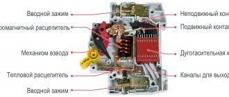
The circuit breaker consists of the following elements: lever (1), screw terminals (2), moving and fixed contacts (3, 4), bimetallic plate (5), adjusting screw (6), solenoid (7), arc extinguishing grid (8) , latches (9)
Using the lever, you can turn on or off the current input to the terminals. Contacts are connected to the terminals and fixed. The moving contact with the spring serves for quick opening, and the circuit is connected to it through a fixed contact.
Decoupling, if the current exceeds its threshold value, occurs due to heating and bending of the bimetallic plate, as well as the solenoid.
Triggering currents are adjusted using an adjusting screw. In order to prevent the occurrence of an electric arc during contact opening, an element such as an arc extinguishing grid was introduced into the circuit. There is a latch to secure the machine body.
Selectivity, as a feature of relay protection, is the ability to detect a faulty system unit and cut it off from the active part of the EPS.
Here is a diagram of the switchboard, clearly showing how the load is distributed throughout the apartment. Before installing the machine, you need to calculate the total power of the equipment that will be connected to it
The selectivity of automata is their ability to work alternately. If this principle is violated, both circuit breakers and electrical wiring will heat up.
As a result, a short circuit on the line, burnout of fusible contacts and insulation may occur. All this will lead to failure of electrical appliances and fire.
Let's say there is an emergency on a long power line. According to the main rule of selectivity, the machine closest to the damage site is triggered first.
If a short circuit occurs in an outlet in an ordinary apartment, the protection of the line of which this outlet is part should be activated on the panel. If this does not happen, it is the turn of the circuit breaker on the panel, and only behind it - the input one.
Absolute and relative selectivity of protection
The concept of selectivity is defined by GOSTotm IEC 60947-1-2014 . There are two types of selectivity - absolute and relative. If the protection is coordinated in such a way that it operates exclusively within the protected area, then this indicates its absolute selectivity.
In these circumstances, the maximum selectivity current becomes the same as the maximum breaking capacity of the circuit breaker located below.
Triggering as a backup, when a shutdown has not occurred in the problem area, is called relatively selective protection. In this case, the switches located above are turned off.
If the specified current value of the circuit breaker is exceeded, i.e. in the absence of large overloads, selective protection operates almost without fail. It is much more difficult to achieve this with short circuits.
Enterprises post data on manufactured products on the device body and on their websites. It is important to read the markings of machines correctly - bundles of switches are formed only according to the tables of one specific manufacturer. It should be borne in mind that groups organized on a relative basis have a large number of functions.
The selectivity tables that manufacturers attach to their products simplify the task. Using them, groups with selectivity of operation are created
The letter “T” in the table indicates the complete selectivity of a pair of devices, and the number indicates partial selectivity. When the expected fault current limit value is less than the number given in the table, selectivity will be ensured
To check the selectivity between the machine above and below, find the intersection of the vertical and horizontal. Ensuring selectivity is a very important task when feeding consumers belonging to a special category.
In its absence, the production process may stop, lines may be damaged, air conditioning systems, smoke removal systems, and others will be turned off.
Comparison table
As it turned out, it’s quite difficult to come up with relevant and important parameters for comparing systems and at the same time fit them into one small table. I came up with this:
*
The "
User Friendly
" setting is extremely subjective, and I understand that. But I couldn’t figure out how else to describe “clumsiness and unreadability.”
**
“
Monitoring not only the network
” implies the operation of the system as a “monitoring system” in the usual sense of the term, that is, the ability to read metrics from the OS, virtualization hosts, receive data from applications in guest OSes, etc.
Types of selective connection schemes
In addition to absolute and relative selectivity, there are 7 more types of selective protection:
- zone;
- time-current;
- energy;
- temporary;
- full;
- partial;
- current
To ensure the required selectivity of auto-protection of electrical networks with circuit breakers, different methods are used. But in any case, it is important to install the switch correctly, following the selected diagram and installation rules.
Type #1 - full and partial protection
Full protection means that if a pair of circuit breakers are connected in series, the appearance of overcurrents causes the one located near the fault zone to shut down.
Partial protection operates on the same principle as full protection, but only after the current reaches the set threshold.
The selectivity of shutdown provided by the circuit breakers (A and B) is that the short circuit, no matter where in the electrical installation it occurs, will be cut off by the nearest switch located above this point. The remaining devices will not turn off
If selectivity is ensured to the smaller of the current values of two AVs, there is reason to talk about complete selectivity between them. In this case, the maximum value of the estimated short-circuit current of the installation under any circumstances will be equal to or less than the current value of the two circuit breakers.
Type #2 - current selectivity type
The main indicator of current selectivity is the maximum current mark. From the object to the input, the values are arranged in ascending order. The operation of this selectivity of protection is based on the same basis as that of time selectivity.
The only difference is that the shutter speed is based on the current value - as the short-circuit point approaches the input, the short-circuit current readings increase. The shutdown time may be the same.
The zone damaged due to a short circuit is determined by the trip setting for different current values. Full selectivity can only be achieved in conditions where the short-circuit current is low, and in the gap between two circuit breakers there is equipment with considerable electrical resistance. In this situation, the short-circuit currents will differ significantly.
This type of selectivity is used mainly in final switchboards. This combines a rated current of insignificant value and a short-circuit current with a high impedance of the connecting cables.
This selectivity option is economical, simple and works instantly. However, often the indicated selectivity may be partial because the highest current is usually small.
The photo shows current selectivity using AV. With this type of selectivity, there is a displacement along the current axis of the current characteristics of machines located one after another
When the values of Isd1 and Isd2 are the same or extremely close, then Is - the maximum selectivity current is equal to Isd2. If these values are much different, Is = Isd1.
The condition for ensuring current selectivity is the following inequalities: Ir1/Ir2 > 2 and Isd1/Isd2 > 2. In this case, the maximum selectivity is Is = Isd1.
Disadvantages include the rapid increase in the level of protection settings against high currents. It is impossible to quickly disconnect a damaged chain if one of the machines turns out to be faulty.
When calculating current protection settings, it is necessary to take into account the actual currents passing through circuit breakers operating in automatic mode.
Type #3 - time and time-current option
When there are a number of circuit breakers in a circuit that have identical current characteristics, but different holding times, then in the event of a malfunction they insure each other. The one that is located in close proximity to the damage site will work immediately, the next one will work after some time, etc.
In this 2-level circuit, switch “A” has a dwell time that provides complete selectivity with the characteristics of AB “B”
In the case of time-current selectivity, protective devices react not only to the current, but also to the duration of the reaction. At a certain current value, after some delay time, the protection is triggered, the distance from which to the fault location is less. The working part of the installation does not turn off.
The photo shows a graph of time selectivity using AB. The time-current characteristics of switches B and A do not intersect. They are arranged in steps
The combination of current and time selectivity increases tripping efficiency. When Isc B< Irm A, selectivity is complete and operation occurs instantly. AB, located above, is equipped with two settings: Im A and Ii A. The first is a selective current cut-off, the second is an instantaneous response.
Type #4 - energy selectivity of machines
With energy selectivity, shutdowns occur inside the machine body. The duration of the process is so short that the short-circuit current does not have time to approach its limit value.
The time-current protection system is considered complex. This involves not only the reaction to the current, but also the time during which this occurs.
As the current increases, the response time of the machine decreases. The basis for this type of selectivity is the regulation of protection in such a way that, on the part of the protected object, it operates faster at all threshold current values, compared to the circuit breaker at the input.
Type #5 - zone defense scheme
The zone method is complex and expensive, so it is used mainly in industry. As soon as the current thresholds reach their maximum, data is sent to the control center and the selected machine is triggered. An electrical network with this type of selectivity includes special electronic releases.
When a violation is detected, a signal is sent from the switch located below to the device located above. The first machine must respond within a second. If it does not react, the second one is triggered.
Comparing this type of selectivity with time selectivity, you can see that the response time in this case is much lower - sometimes hundreds of milliseconds. Both the percentage of intervention in the system and the percentage of its damage are reduced. Thermal and dynamic influences on parts of the installation are reduced. The number of selectivity levels is increasing.
When the currents flowing through the protective devices reach a value greater than their own settings, the blocking signal is transmitted by each circuit breaker to the higher level of protection
In the case of zone selectivity, the protection located on the power source side is triggered, if we take the short-circuit location as the starting point. Until the machine is triggered, control is exercised to ensure that the protective device on the loaded side does not give a similar signal.
But such selectivity requires the presence of an additional power source. Therefore, the rational use of this type of selectivity is in systems with high short-circuit current parameters and a significant current. These are switching and distribution devices located on the load side of generators and transformers.
Specialist Glossary
Selectivity - coordination of the operation of protective devices installed in series, so that in the event of an overload or short circuit (short circuit), only that part of the installation where the fault occurred is switched off.
Full selectivity - is ensured when, when two circuit breakers are connected in series, the equipment on the load (consumer) side provides protection without tripping the device on the supply side.
Partial selectivity differs from full selectivity in that the load-side equipment provides protection without tripping the supply-side device only up to a certain overcurrent level Is (selectivity limit current).
Overload zone is the range of current values in which the thermal release (bimetallic plate) is responsible for operation. It is an inverse characteristic.
Short circuit zone is the range of current values in which the electromagnetic release is responsible for operation. Provides almost instant response.
Rice. 1. Overload area and short circuit area
Calculation of selectivity of machines
Proper selection of the machine and correct configuration is the basic principle of maintaining the selectivity of circuit breakers. Selectivity for a switch located near the source guarantees the fulfillment of the requirement: Is.o.last ≥ Kn.o.∙ I k.prev.
Here Iс.о last. - the current value that triggers the protection. I k.pred. — short-circuit current at the end point of the zone covered by the action of the machine, located far from the energy source. Kn.o. — reliability coefficient. Its value depends on the spread of parameters.
The rating of the machine for the circuit is selected not only by calculation, but also according to this table, focusing on the cross-section of the cables in the circuit
The alignment tс.о.last ≥ tк.prev.+ ∆t demonstrates selectivity in the case of time-dependent AV adjustment. tс.о.last, tк.prev. — time intervals for operation of switches located at a great distance from the power source and located nearby. ∆t is a parameter that is taken from the catalog and denotes the temporal degree of selectivity.
Selectivity map and rules for its creation
The time-current characteristics of all devices included in the electrical network circuit are depicted on a selectivity map. The purpose of its compilation is to ensure maximum protection for the machines. The basis of switch protection is the principle by which switches are connected one after another strictly in series.
There are a number of rules that are required when creating a selectivity map:
- Installations must have one voltage source.
- All important design points should be clearly visible. Taking this requirement into account, it is necessary to choose a scale.
- The map indicates the protective properties, minimum, maximum short circuit parameters at points in the system.
Often design standards are violated, and selectivity maps are missing in projects. This may lead to interruptions in power supply to consumers.
The characteristics of machines connected in series one after another are plotted on the map. The diagram itself is built in axes
The map gives a complete picture of the coordination of settings. It provides an opportunity to compare the operation of machines based on such characteristics as selectivity.
Time-current varieties of axes are the basis not only for constructing selectivity maps for current protection in the form of circuit breakers, but also for its other types: fuses, relays. Typically one card contains 2-3 AB characteristics. The abscissa axis shows the current value in kV, and the ordinate axis shows the time in seconds.
What are time-current characteristics?
Hoping that the reader is prepared, I will be brief and talk only about what relates to the topic of the article. The letters B, C and D are the main characteristics of the electromagnetic release. The letter indicates the range of instantaneous tripping currents. At the beginning of this range, the EM release should not operate , within the range it may operate , and at an overcurrent equal to the upper end of the range (or more), it should operate . The range limits can be illustrated using simplified graphs for three AVs with the same rated current of 10 A, but with different shutdown characteristics:
Graphs for one rated current and different tripping characteristics
The thermal release graph, shown as a smooth thick line, is the same for all three circuit breakers. But the ranges of instantaneous tripping currents (shaded in blue) are different.
With an overcurrent of up to 11.3 A, our three switches should never turn off. As the current increases, the turn-off time decreases down to seconds, and when operating in the so-called short-circuit current zone, the turn-off time can be tens or even a few milliseconds. All currents that exceed the marked ranges shall result in instantaneous tripping.
Details about the time-current characteristics of circuit breakers can be found in GOST IEC 60898-1-2020.