An experienced radio technician and amateur will find universal measuring equipment useful. The oscilloscope program for PC will help you study the shape of digital and analog signals, process and save research results. Such kits are used by amateurs and professionals when setting up, troubleshooting and repairing amplifiers, power supplies, and other equipment.
Visual presentation of information is a significant advantage of a software oscilloscope
About virtual oscilloscopes
Any personal computer (PC), even with “slow” processors and an outdated Windows XP operating system, is suitable for working together with specialized set-top boxes. However, a high-quality virtual oscilloscope connected to a standard USB port is expensive. A thorough search for suitable models of equipment on foreign online trading platforms does not solve the problem. Buying used equipment is associated with increased doubts and the absence of real guarantees.
At the same time, a superficial study of the topic is enough to understand the relative simplicity of this problem. Every PC has a sound card. Creating an input signal limiter regulator does not cause excessive difficulties. The measurements can be converted into a convenient form using a special simulator program. The instructions below will help you create a virtual oscilloscope quickly, without errors and extra costs.
Read online Oscilloscope is your assistant (how to work with an oscilloscope)
An electronic oscilloscope is a universal device that can become an indispensable assistant for a radio amateur. Analysis of the shape and passage of signals through various circuits on the oscilloscope screen makes it clearer to set up radio devices and troubleshoot them.
The proposed book is devoted to techniques for working with an oscilloscope. Various examples of observation and measurement of electrical signals in radio circuits are given. A technique for visual inspection and adjustment of various cascades of radio devices is given.
The book is intended for a wide range of radio amateurs.
Ivanov B.S. “OSCILLOSCOPE IS YOUR ASSISTANT” (how to work with an oscilloscope) Supplement to the magazine “Radio” Issue No. 1
From the author
Without an electronic oscilloscope today it is unthinkable to quickly and efficiently configure almost any device - from a detector receiver to a TV. An oscilloscope is the “eyes” of a radio amateur, allowing one to enter into the world of electronic processes in radio structures, observe the signal shape and measure its parameters such as the amplitude and duration of pulses, the rate of their rise and fall, the amplitude of rectified voltage ripples, the frequency of electrical oscillations, and voltages in various cascade circuits. . An oscilloscope will not only significantly simplify the adjustment of designs, but will also help you quickly and better master the theoretical foundations of radio engineering, carry out many interesting experiments, experiments, and various research projects.
Of course, all this will become real only with a good knowledge of the oscilloscope structure and mastering the technique of working with it.
One of the most popular and available for purchase oscilloscopes today is OML-3M, produced by Saratov Production Association named after. S. Ordzhonikidze. It is small-sized and easy to use, its parameters are quite consistent with many types of measurements encountered in amateur radio practice. Its predecessor was OML-2M, and even earlier - OML-2-76. The methodology for a wide variety of measurements using an oscilloscope in this series is described in this brochure. Although, of course, the material will be useful for owners of other oscilloscopes.
In one of the subsequent brochures, the Appendix under the same name is supposed to talk about electronic attachments for the oscilloscope, which significantly expand its capabilities.
A little theory
The word “oscilloscope” is derived from “oscillum” - oscillation and “grapho” - writing. Hence the purpose of this measuring device is to display current or voltage curves as a function of time on the screen. There is also another name for this device - oscilloscope (from the same “oscillum” and “skopeo” - I look) - a device for observing the shape of vibrations. And although the second name is more accurate, the first name is still used in the literature - oscilloscope.
The main part of an electronic oscilloscope is a cathode ray tube (Fig. 1), reminiscent in shape of a television kinescope, only of much smaller dimensions. The tube screen is coated on the inside with a phosphor - a substance that can glow under the “impacts” of electrons. The greater the flow of electrons, the brighter the glow of the part of the screen where they fall.
Electrons are emitted by the so-called electron gun, located at the end of the tube opposite to the screen. Between the gun and the screen there are control electrodes - a modulator that regulates the flow of electrons flying towards the screen, two anodes that create the necessary acceleration of the electron beam and its focusing, and two pairs of plates with which electrons can be deflected horizontally ( X ) and vertically ( Y ) axes
The screen of a cathode ray tube will glow only when certain voltages are applied to its electrodes. An alternating voltage is usually supplied to the filament, a constant negative polarity is applied to the control electrode (modulator) with respect to the cathode, and a positive voltage is applied to the anodes, and the voltage on the first anode (focusing) is significantly less than on the second (accelerating). The deflection plates are supplied with both a constant voltage, which allows the electron beam to be shifted in any direction relative to the center of the screen, and an alternating voltage, which creates a scan line of one or another length, as well as “drawing” the shape of the vibrations under study on the screen.
To imagine how the shape of oscillations on the screen is obtained, let us conventionally depict the screen of the tube in the form of a circle (although for the 6L01I tube in OML-2M and OML-3M it is rectangular) and place deflection plates inside it (Fig. 2).
If you apply a sawtooth voltage to the horizontal plates X 1 and X 2, a luminous horizontal line will appear on the screen - it is called a scan line or simply a scan. Its length depends on the amplitude of the sawtooth voltage.
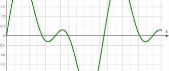
If you now apply an alternating voltage of a sinusoidal shape to another pair of plates (vertical - Y 1 and Y 2), for example, the scan line will exactly “bend” according to the shape of the oscillations and “draw” an image on the screen.
If the periods of sinusoidal and sawtooth oscillations are equal, the screen will display an image of one “sinusoid”. If the periods are unequal, as many complete oscillations will appear on the screen as their periods fit into the oscillation period of the sawtooth sweep voltage. The oscilloscope has an adjustment of the sweep frequency, with the help of which the desired number of oscillations of the signal being studied is achieved on the screen.
Functional Features
Oscilloscope - concept and design of the device
Even a low-power computer can become the basis of the equipment. In some situations, laptops are preferable. Portable models can be used to troubleshoot problems in cars.
Other functional features worth noting:
- a coupling capacitor is installed in the standard input circuit of the audio card, so without disassembling and making changes to the circuit, it will be possible to display only the variable component of the signal on the screen;
- minimum amplitude 0.5-2 mV (determined by the technical characteristics of the audio path);
- the maximum input signal is chosen with virtually no restrictions, since for several tens or hundreds of volts you only need to create an appropriate voltage divider;
- The frequency range is also determined by the basic TX of the computer, usually from 10 Hz to 22 kHz.
Oscilloscope online
When you debug something based on modern microcircuits, an oscilloscope is an irreplaceable thing!
If you do this all the time, then it’s better to buy a good one and not a cheap one, but if you do something from time to time and not seriously, then buying a device that will only take up space 90% of the time is a suffocation.
And this toad is doing the right thing!
After all, there is a whole section of software called Osciloscope Audio.
I became acquainted with such software on the Specrum ZX-80, the essence is simple - we connect a probe to the microphone (or line) input, launch the program, poke it into the board and watch the signal.
The main thing to remember is that the computer directly normally “digests” only a five-volt or lower voltage signal.
But almost all the logic on the chips is just 5 or 3.3 Volts, so that’s quite enough.
At one time, all software sites were inundated with Osciloscope programs. Nowadays websites have degenerated and software on the Internet often contains Trojans.
But oscilloscope applications for smartphones have appeared.
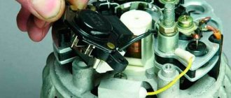
Here is an example - viewing the signal from the trainer connector of the remote control.
Using such a software oscilloscope, you can easily find the output from the logic to the RF transmitter in the control panel for connecting an external RF part on those panels where this is not provided for by the design.
A lot of software is paid, but downloading broken versions is problematic; you can run into the already mentioned Trojans and viruses.
But, I was doing some searching the other day and found an online built-in oscilloscope. So I'm adding it to the article.
Online oscilloscope for aircraft modeller
I hope there is no need to describe how to work with its interface, it is quite clear and you can always figure it out at random.
Konstantin, Radio-controlled aircraft models
Converting a Computer to an Oscilloscope
DIY oscilloscope
After clarifying the initial computer data and personal needs, they begin to select an electrical circuit.
To get acquainted with professional solutions, you can study the designs of serial measuring instruments
Set-top box diagram
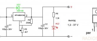
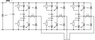
For high-quality reproduction without extensive practical experience, it is better to choose relatively simple designs. However, the electrical circuit presented below is quite capable of ensuring minimal signal distortion while simultaneously performing protective functions.
This adapter circuit can be created quickly without unnecessary difficulties
Description:
- the set-top box resistors are evaluated in conjunction with the Rin of the computer in order to correctly calculate the divider parameters;
- capacitors equalize the frequency response;
- Zener diodes installed in the manner shown in the figure prevent damage to the computer’s audio input when a high-amplitude signal is supplied (switch position “1:1”);
- additional current protection is provided by R1.
You can hardly count on complete passport data, especially if you have old computer equipment. Most likely, you will have to measure the impedance at the sound card input. To do this, a reference signal (50 Hz, sinusoid) is created at the output of the same block using a special “Virtual Generator” program. The following calculation is performed using the formula:
Rx=R1*(U1/(U2-U1)).
Example:
60*(120/(520-120))= 18 kOhm.
Knowing the input resistance, create a voltage divider using one of the presented circuits
For your information. By installing a “tuning” resistor in parallel, you can precisely adjust the parameters of the divider.
Set-top box collection
To eliminate the parasitic influence of external electromagnetic radiation, the set-top box is placed in a metal case. It can be created from a suitable duralumin sheet with a thickness of 1.5-2 mm. A CP-50 type connector is attached to the input so that standard probes can be connected without problems. The output is a flexible cable with a Jack plug that matches the input jack of the computer audio card. For assembling a simple electrical circuit, surface-mounting technology is quite suitable.
The RadioMaster virtual oscilloscope allows you to study alternating voltages in the audio frequency range: from 10 Hz to 20 kHz through two channels with an amplitude from several millivolts to two to three hundred volts. Such a device has obvious advantages over a real oscilloscope. The program determines the period, frequency and amplitude of the signals. In addition to the oscilloscope itself, the device contains a spectrum analyzer and can work as a dynamic two-terminal curve tracer. The disadvantage of such an oscilloscope is the inability to see and measure the DC component of the signals. The instrument panel contains controls typical of real oscilloscopes, as well as special settings tools and buttons for working in waveform storage mode. All panel elements are equipped with pop-up comments, and you can easily understand them. The comments in parentheses indicate keys that duplicate on-screen controls. If you do not have a virtual lab base unit, you will have to make the cable yourself. By analogy with the block, this circuit provides two stages of voltage division for each channel: into a range of plus-minus 12.5V (full swing up to 25V), and plus-minus 250V (ampl. 500V). There are corresponding switches on the instrument panel. If there is no need to measure large voltages, the second stage can be omitted. Cable diagram. It is recommended to use special high-voltage resistors with a dissipation power of at least 0.5 W as R1 and R1′. There is a grid on the oscilloscope screen, where the horizontal line is time (the division value in microseconds is indicated at the Sweep Range switch on the X panel), and the vertical line is voltage in volts. The vertical marking corresponds to channel 1; for channel 2 there is only scale digitization. Switching to the spectrum analyzer mode is carried out by the Spectrum On/Off button or the Z key. A panel with analyzer controls appears at the bottom of the form. So you can move the right and left boundaries of the frequency range within the original range, which lies between 0 and half the sampling frequency of the ADC card. The vertical scale of the spectrogram view can be changed using the arrow keys. The dynamic curve tracer mode is turned on by the Y(X) On/Off button or the X key. This is actually a two-dimensional oscilloscope. Real devices with an additional input X were used to compare the frequencies and phases of the signals using Lissajous figures. You can do simple experiments with phase shifting C or L, as shown in the figure. Scheme U1-U2(U1) for air conditioner. 0.33 μF at f = 1.5 kHz U1-U2(U1) for the KS133G zener diode. But of greater interest is reading the characteristics of nonlinear two-terminal devices - various diodes, thermistors, etc. (in diagram Z). In the absence of a base unit, you will additionally need a sinusoidal voltage source with a frequency of 1..2 kHz and an amplitude of up to 15..20 V, as well as a resistor Rm of approximately 1 kOhm. There are options for representing four types of dependencies. The coordinate axes of the curve tracer are marked and digitized in true voltage or current values if the device has been calibrated. Let us especially focus on the voltage calibration operation, which should be performed after connecting the cable you made. Apply a 12.5V signal to both inputs of known amplitude from a common source (preferably a sine wave with a frequency of 500..2000 Hz and an amplitude of 15..20V, press the Calibration button, enter the actual amplitude value in millivolts, press Enter, and the oscilloscope is calibrated to the inputs 12.5 V. Next, if necessary, calibrate the second stage. To do this, apply a 250 V alternating voltage with an amplitude of 150..200 V to both inputs. Set the switches on the screen panel to 12.5 V. Read the measured values - 1 green channel, 2 - red. Divide the actual value into the measured ones, these are the attenuation coefficients (should be about 20). Write them with a text editor (in Notepad) in the CALIBR file, lines 8 and 9, respectively. If you have a base unit, it is not necessary to do calibration, it is prepared To you by the manufacturer. The program remembers all settings and settings and restores them the next time you turn it on. The characteristics of the oscilloscope largely depend on the parameters of the sound card of your computer. So with older types of cards, which have a sampling frequency of no more than 44.1 kHz, the frequency range of the device is limited from above. Using the sample rate switch on the panel, try out your sound card. Already at 96 kHz, signals up to 20 kHz can be viewed with confidence. On the contrary, it is more convenient to study infra-low frequency signals at a low sampling rate. The ADC bit size is set to 16, which ensures fairly high accuracy. If your sound card does not have a line input, use the microphone input, but one oscilloscope channel will be lost and Y(X) mode will not be possible. Don't forget to specify the selected sound card input in Windows settings. Set the corresponding volume control to the maximum position, the balance control to the neutral position. You can try this program without a special cable - from a virtual signal source, for example, playing a sound file. In this case, specify Stereo Mixer as the recording input. Do not connect the device input to a 220 V network, even through a large resistance or autotransformer. At best, you will lose your computer. SourceThe best oscilloscope software for Windows PC
The following sections provide brief overviews of popular specialized programs. When choosing, you should pay attention to ease of learning, interface language, and other details, taking into account the needs of a particular user.
FrequencyAnalyzer
The program was created for processing audio signals. It is permissible to change the measurement frequency. User-selectable 8 (16) digit conversion helps establish the required accuracy. The disadvantage is the lack of a Russified version.
Winscope
This online oscilloscope does more than just show the signal. When you select the appropriate mode, Lissajous figures are displayed on the screen. The user can examine the spectral distribution in the range from 20Hz to 20kHz.
Sound oscilloscope
The 2ray Oscilloscope is well suited for studying two signals. If necessary, waveforms can be saved as graphic files. The clear interface simplifies the use of the program.
Oscilloscope Spectrum in real time
Multi-Instrument contains not only an oscilloscope, but also a generator. This software suite is complemented by a spectrum analyzer. Such equipment is suitable for complex testing of radio equipment.
Best Oscilloscope Software for Windows PC
Winscope
Winscope is free oscilloscope software that can be used to analyze any signal on your computer. When you input a signal, it allows you to view its spectrum, measure frequency, plot graphs, view FFT spectrum, save signal data, and more. It reads the input signal through your computer's 3.5mm audio jack.
To start signal analysis after connecting the input signal, click the Play button on the Winscope interface. You will start viewing the signal spectrum right on the main window, where you will also find various options for analyzing the input signal:
- Trace Modes: Three spectral tracing modes are available. These are YT Single Trace, YT Dual Trace and XY Mode.
- View spectra in line or scatter plots.
- FFT mode: Converts the input signal to display amplitude and time spectra into amplitude and frequency spectra.
- A correlometer option is also available. It allows you to find the correlation between two sound sources.
- Save analysis data in DAT format to your computer.
Visual Analyzer
Visual Analyzer is another good oscilloscope program for Windows 10. This utility has a signal spectrum analyzer. In addition, you will find many tools for viewing signal-related data, determining the values of various parameters, measuring frequency, applying filters, and much more. This oscilloscope has two displays for signal spectra; one displays the normal spectra of the signals, and the other displays the FFT of the signal.
On the left side of the interface you will find buttons for changing spectra viewing options. You can change the scaling factor, ms/d value, X and Y graph positions, etc. Some values can be found such as: frequency, average, crest factor, peak voltage, ZRLC, phase, channels, etc. Options for area or spectrum capture are also available.
The best thing about this tool is that it is an oscilloscope with filters for Windows. You can apply various filters to the input signal, then measure values and view spectra.
This is a comprehensive oscilloscope software with tools for thorough signal analysis.
Soundcard Oscilloscope
Soundcard Oscilloscope is feature-rich oscilloscope software that is free for personal use only. This app has a signal generator and various other tools. The input signal is displayed in the program interface on graphics. You can change the spectrum plot options to closely view and analyze signal spectra in real time. Set different channel amplitudes or sync channels for a common amplitude. Set the time scale from 1 minute to 10 seconds. You can also set different channel modes: Single, CH1 - CH2, CH1 + CH2 or CH1 x CH2.
Signal measurement tools to determine frequency and voltage are also available in the program. Real-time values are displayed directly on the screen.
Other tools are available on the corresponding tabs. View XY graph or view frequency graph. The Signal Generator tab allows you to generate a signal manually. You can generate a custom signal for channels. Generate sine, triangle, square, sawtooth, pink or white noise. Set the signal amplitude, frequency, etc. The signal generator output can be heard through the speakers connected to your PC. The generated signal can also be recorded on your computer in WAV format.
Use in everyday life
During operation, the following recommendations should be used:
- the computer together with the set-top box is grounded before performing measuring operations;
- use a range suitable for a certain signal amplitude;
- stop working if the electrical insulation is damaged or other dangerous faults are detected.
The presented oscilloscopes for PC, when properly assembled and configured, provide fairly high accuracy. However, we must not forget that even specialized devices in this category are intended rather to study the shape of signals. Such problems can be solved using the equipment discussed in the publication.
Design and Application
An oscilloscope is a complex electrical device. A block diagram will help you understand the principle of its operation.
There are two scanning beams : vertically - Y and horizontally - X. Time values are plotted along the X axis, and the signal amplitude is displayed along the Y axis.
Y receives a signal from the device . It then passes through an attenuator, which changes the sensitivity of the circuit. Then, after passing through the pre-amplifier, it enters the delay line , which “holds” the signal until the sweep generator operates. The final amplifier outputs the signal to the oscilloscope screen. The higher the input voltage, the greater the amplitude of the signal.
A sawtooth voltage is applied to X from the sweep generator, due to which the signal on the oscilloscope is “stretched” in time. By changing the generator dimension, you can obtain an image with a scan time of up to thousandths of a second.
To ensure that the sweep starts simultaneously with the arrival of the signal, the device has a synchronization system . There are 3 possible clock sources:
- Measured signal . The most commonly used option, especially when the incoming source frequency is constant.
- Electrical network . The network frequency is maintained with high accuracy, so synchronization is possible through it.
- External source . It is used both as a laboratory signal generator and as a smartphone with an application that generates clock pulses of a certain frequency.
The oscilloscope visualizes the waveform , which helps to understand the cause of the malfunction. Using the device, the frequency response of the device is measured, it is possible to find out the rate of rise of the pulse in digital devices.
Oscilloscopes are used to configure and repair electronic devices, be it household appliances, vehicle repairs, or orbital stations.