Electrical laboratory » Electrical laboratory services » Measurement techniques » Methodology for testing circuit breakers with voltages up to 1000 V
1. General Provisions.
This technique is intended for measuring the response time of protection devices with thermal and electromagnetic releases in order to verify compliance with the requirements of paragraph 413 of GOST R50571.3-94, which ensures the safety of indirect contact with non-current-carrying metal parts of the equipment at the moment of short circuit of the phase conductor. Conducted by electrical laboratory engineers.
The disconnection time for distribution circuits should not exceed 5 s if the protective earth resistance is less than
(50/U0)*Z0
where Uo is the rated phase voltage,
Zo - phase-zero circuit resistance,
those. low enough to provide a safe touch voltage on metal parts of the equipment, and 0.4 s for circuits supplying mobile and portable equipment and for distribution circuits in which the above condition for protective earth resistance is not met.
Application area
The recommendations of this method are used when checking and testing circuit breakers, overload protection devices for electric motors (thermal and other types of relays), various starters and simple relays, as well as load switches for voltages up to 1 kV.
Devices used to turn on and off the main circuits in systems that generate electrical energy and transmit it to consumers are energy distribution switching devices. They turn the circuit on or off when operated by maintenance personnel or automatically.
Power distribution switching devices perform two functions:
• Non-automatic switching on and off of electrical circuits that occur when it is necessary to supply or remove power from a network section
• Automatic shutdown of electrical circuits in the event of any phenomena appearing in them that threaten the safety of operating personnel or the safety of the installation (for example, in the event of short circuits). Sometimes devices automatically turn on a backup power source or automatically turn on again after an emergency shutdown.
The following groups of switching devices are distinguished:
• Automatic switches (automatic machines)
• Fuses (fuses)
• Non-automatic switches
Sometimes these devices are installed together with control equipment in devices for controlling electric drives (control stations, magnetic starters, etc.).
Contactors, starters, rheostats, relays that protect and control the operation of an electric drive are called control devices.
Abnormal modes are those in which there is an excessive decrease in voltage, and, in particular, the flow of overcurrent (current greater than the rated one).
An extreme drop in voltage can cause the motor to stop and then, when full voltage is suddenly restored, to start at the wrong time. Therefore, sometimes automatic switches are used on critical branches to the receiver, turning off the circuit when the voltage drops to 35-70% of the rated voltage. Restarting must be done under operator intervention.
The most dangerous and frequently occurring abnormal mode is the flow of overcurrent during a short circuit or excessive current consumption by electrical energy receivers. The shutdown equipment must reliably switch all currents, up to the highest short-circuit current that may occur at the place of its installation. Non-automatic switches at these currents should not be damaged and switch off spontaneously.
Control equipment (contactors, starters) is designed mainly for switching currents not exceeding the overload current of electric motors (no more than 10 times the rated value). The control equipment for individual electrical receivers is protected from short-circuit currents using energy distribution equipment.
For uninterrupted operation of the installation, it is necessary to ensure selectivity (selectivity) of shutdown of control equipment and power distribution equipment, as well as selectivity of shutdown of several devices connected in series. This means that when overload currents arise in a branch to a separate receiver, the corresponding section of the circuit must be turned off by the control equipment of this receiver, and not by the switchgear equipment installed on the branch. If a short circuit occurs on a branch, the power distribution device must be switched off, not the control device.
Selectivity is especially important in a power distribution system. For all overcurrent values, up to the maximum short circuit current, only one device located closer to the accident site should be turned off; all other devices with a higher rated current located closer to the energy source should not be turned off.
It would be desirable to have such a protective characteristic that in the entire range of overcurrents there is a time delay inversely dependent on the current (the higher the current, the shorter the shutdown time), since the destructive effect is greater, the higher the current and the duration of its action. For design reasons, devices are often used that, at currents greater than a certain value, operate instantly (without a deliberately created time delay). For the same reasons, devices that have a time delay independent of the current are sometimes used.
After turning off the device during overcurrents, it is advisable to turn it on as soon as possible. For this purpose, switches are used, except automatic ones with thermal control elements, which allow immediate activation after operation. Automatic switches with thermal elements must allow restarting no later than 1-3 minutes after shutdown during overcurrents. If the circuit breaker trips without overload, it must be capable of immediate reclosure.
How are machines checked by an electrical laboratory?
Any electrical network is a potential source of two hazards: electric shock and the possibility of fire due to a short circuit. And if the first factor is present only in networks with voltages above 42 volts, then the danger of a short circuit remains even in low-voltage wiring. In this connection, checking circuit breakers is a mandatory item in the estimate of both acceptance and scheduled maintenance tests performed by the electrical laboratory.
Unlike differential monitoring of leakage currents, this category of protective equipment has been present in electrical networks since their inception, so the technology for testing them is quite strictly standardized.
Test object
Automatic switches (automatic circuit breakers) are designed for infrequent opening and closing of an electrical circuit and long-term passage of current through it, as well as for automatic opening of circuits when various abnormal conditions appear in them; circuit switching occurs between mechanically moving contacts.
Automatic machines are divided into slow-acting and high-speed. High-speed ones are characterized by their own response time, that is, the time from the appearance of the short circuit current until the contacts begin to diverge.
Low-speed machines include machines that usually do not have special performance requirements or these requirements are low. To hold the contact system in the on position, latches are used. These machines have their own response time from 10 to 100 ms and do not have a current-limiting effect.
Based on their design, they distinguish between machines with a plastic cover and body (for currents up to 630A inclusive) and machines without a case and cover (for currents from 630 to 1000A inclusive).
High-speed circuit breakers, manufactured for rated direct currents of 1500-15000A, have their own shutdown time at high currents of no more than 5 ms. Their characteristic feature is that the entire design is subject to the requirement of increasing performance.
Figure 1 shows an AR series circuit breaker in a withdrawable version. To extinguish the arc, spark arresting chambers are installed above the switch contacts (Figure 2). Both machine buses (1) at the output ends are equipped with vertical connecting flags (4,5), which allow direct fastening of the retractable contacts. The circuit of arcing contacts is formed by two movable arcing contacts (3), which are connected to the circuit of the main contacts by means of flexible copper belts. Instant shutdown is ensured by a spring accumulator (8) through a lever transmission and a release mechanism (7). The machine is turned on either using a button on the front panel or using a switching electromagnet (17). Switching off is also carried out using the red button u1082, or using an electromagnet (18). The battery is tensioned automatically, after turning on the machine, by the drive (10). This operation can be performed manually using a lever transmission (9).
BA series circuit breakers can be manufactured in various modifications. To do this, additional parts are installed on the machine, which ensure its withdrawable version (Figure 3, lower part), stationary version (Figure 3, middle) or stationary version with manual execution (Figure 3, upper part).
Methodology for checking circuit breakers
Before checking the modular switch, its rated current and operation frequency are determined. Then, using the characteristic, the time range within which the thermal protection fits at three times the rated current is found. This is how they test it.
The machine is connected to the testing device. First check the cutoff . The machine is turned on and current is passed through it for a short time, increasing its value in steps. Most devices perform current raising and time delay between steps automatically.
Pauses during lifting are necessary in order to prevent premature activation of thermal protection . After operation, the cut-off current is recorded, and the machine is immediately turned on again. If it does not turn on, then it is not the cutoff that has triggered, but the thermal protection. This rule does not apply to circuit breakers with semiconductor releases.
Then the machine is allowed to cool a little and the thermal release is checked . The current is increased in steps to three times the rated current. Pauses are made so that the bimetallic plate of the release does not begin to bend prematurely. In this case, the test results will be distorted.
Simultaneously with the start of the stopwatch, current is supplied. The time during which the protection was triggered is recorded and compared with the range determined by the characteristic.
If the measured parameters leave the permissible range, the machine is rejected. If the thermal protection does not operate within the maximum time determined by the characteristic, the test is stopped. Otherwise, the heat will cause the body of the machine to melt.
For three-pole switches, all three phases are checked; their response characteristics are approximately the same, but not identical - their protection elements are different and each has a range of parameters.
Determined characteristics
Visual inspection.
An external inspection determines the condition of accessible parts of circuit breakers and control devices for visible damage, the presence of chips in insulating materials, the absence of fastening parts, etc.
Insulation resistance measurement.
The insulation resistance is measured between each wire (pole) of the device and the ground, as well as between every two wires (poles). The insulation resistance must be at least 1 MOhm.
When measuring the insulation resistance of circuit breakers together with the cables and wires connected to them, the insulation resistance must be at least 0.5 MΩ.
High voltage test.
The test is carried out during commissioning, major repairs, and also in case of unsatisfactory results of insulation measurements.
The test voltage value is 1 kV 50 Hz. test duration is 1 minute. During routine repairs, instead of testing with alternating voltage, it is allowed to carry out a one-minute insulation measurement with a megger at a voltage of 2500V.
Checking the operation of maximum, minimum or independent releases of automatic machines and control devices.
The operation of the releases must comply with the factory data and the requirements for ensuring protective characteristics.
Checking the operation of contactors and circuit breakers at reduced operating voltage.
The operating voltage value and the number of operations are given in Table 1.
| Operation | Operating voltage | Number of operations |
| Inclusion | 0.9Unom | 5 |
| Shutdown | 0.8Unom | 5 |
Checking fuses.
The fuse link must be calibrated.
When is verification necessary?
According to the requirements of the PUE and PTEEP, the serviceability of circuit breakers is monitored in all cases of official electrical testing.
That is, such a need arises:
- when certifying a product after its development;
- when putting an electrical installation into operation (acceptance tests);
- during scheduled maintenance checks of the electrical network;
- after major, planned or emergency repairs.
During the tests, the circuit breaker is loaded with powerful current pulses and the time parameters of the actuation process are recorded. Since in this case the boundary between “pass” and “fail” lies within a few milliseconds, there can be no talk of any independent conclusions about the performance of the device.
Any option for independent checks (including activation of the “test” button in those devices that have one) will only confirm the fact that the mechanical system is working, but not the correctness of the device adjustments.
An official expert opinion on the compliance of the characteristics of an automatic release with the norms and requirements stated in the relevant standards can only be given by a certified electrical measuring laboratory.
Test and measurement conditions
Testing of automatic machines and control devices is carried out at an ambient temperature not lower than +100C.
Checking the maximum releases of automatic machines and starters should be carried out taking into account the introduction of temperature corrections since the temperature of the maximum releases made on the basis of bimetal has a significant impact on the time characteristics of the machines. Current corrections for temperature are shown in Table 2.
Ambient air humidity is important when conducting high-voltage tests, because... Condensation on the insulating parts of devices can lead to breakdown of insulation and, accordingly, to failure of the equipment (both testing and under test). Before carrying out high-voltage tests, the devices should be wiped free of dust, dirt and moisture.
Atmospheric pressure does not have a special impact on the quality of the tests.
Switch testing devices
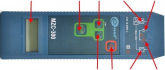
The complexes used to test switches are specially designed for this purpose. An exception is the devices of the RETOM , which are initially designed to test relay protection, but can also be used to supply currents to the contact system of the circuit breaker with control of the moment of shutdown.
RETOM-21 is most suitable for this purpose . Testing the operation of the thermal release is carried out by applying a continuous current simultaneously with starting the device’s stopwatch, configured to record the disappearance of the current during shutdown. Electromagnetic releases are tested by currents supplied by pulses of duration set by the user. With a gradual increase in current, the overload protection of the machine will inevitably trip.
RETOM-21
An important advantage of RETOM is that the current supplied for testing is sinusoidal . Most other devices specifically designed for testing machines produce a pulse current generated by thyristor regulators . But their dimensions are smaller and management is simpler.
Device for testing automatic machines RT-2048
There are many such devices. To check the cutoff, they also supply current with increasing amplitude pulses of adjustable duration, and to check thermal protection, the required current is set and the stopwatch is started.
Measuring instruments
Automatic machines and control devices are tested in assembled form, with all parts and assemblies installed on them that may affect the test result.
Before testing, an external inspection is carried out, checking the integrity of the housings and insulation. Insulation resistance is measured using megohmmeters for voltages of 1000V and 2500V.
Measuring the resistance of contacts and contact connections inside devices is carried out using direct current bridges (for example P 333), which allow measurements to be made with an accuracy of 0.001 Ohm, or by the ammeter and millivoltmeter method. When carrying out measurements using the ammeter-voltmeter method, the operating current should not exceed the rated current of this device.
Testing with increased power frequency voltage is carried out using various installations, which consist of the following elements: test transformer, control device, instrumentation and protective equipment. Such devices include the installation AII - 70, AID - 70, as well as various high-voltage test transformers, which have a sufficient level of protection and are adequately prepared for testing. To control the quality of bolted connections, plumbing tools in the form of wrenches, etc. are used.
What are the stages of checking circuit breakers?
According to GOST R 50031-2012, the full test cycle of circuit breakers consists of the following stages:
- control of marking durability;
- checking the reliability of screw connections;
- testing of outputs for external switching;
- control of the electrical safety of the device (protection against electric shock);
- checking the electrical resistance of dielectrics involved in the design of the device;
- temperature compliance test;
- performance testing during long-term load application (28-day test cycle);
- measurement of shutdown characteristics during operational operation of the device;
- checking the switching capacity of the device;
- short circuit current resistance;
- control of resistance to mechanical shocks;
- performance testing under conditions of elevated ambient temperature;
- checking compliance with fire resistance standards (that is, the time of maintaining switching characteristics under fire conditions or critical thermal load);
- testing the resistance of a dielectric to the formation of current-carrying channels (tracking resistance);
- checking the corrosion resistance of the structural elements of the device when operating in a normal or aggressive environment (corrosion resistance).
The given list of tests was developed, first of all, for the initial certification of new products and is carried out in full only after the development of a new device (the price of such a “research” is much higher than conventional laboratory tests).
Operational tests in electrical installations carried out by ETL are developed based on three basic stages:
- checking trip characteristics;
- switching capacity control;
- test for resistance to short circuit currents.
Trip characteristics measurement
The purpose of this stage of testing is to determine the actual operating settings of the device and their compliance with the current characteristics specified in the factory documentation of the device.
The tested characteristics in this case are:
- rated operating current;
- shutdown time;
- instantaneous current and time (checking the electromagnetic release);
According to the standard, this testing stage must also be accompanied by checking the stability of protection parameters when the ambient temperature changes. But in the operational technology for testing electrical installations up to 1000, this item, as a rule, is included only in the presence of appropriate production conditions.
Switching capacity monitoring
To confirm the functionality of a circuit breaker, it is necessary not only to check its overload detectors, but also to perform a breaking capacity test under normal and critical load.
This test consists of repeatedly performing the “on-off” cycle, followed by checking the contact resistance of the contacts.
Short circuit current resistance
Since the rated operating current of the circuit breaker is significantly less than the short-circuit current, this stage of electrical testing is intended to confirm the functionality of the device after passing short-circuit currents through its poles.
The test is considered successful if the switching mechanism remains operational and the contact resistance remains within the normal range.
Procedure for testing and measurements
Visual inspection.
External inspection of automatic machines and control devices is carried out by opening the housing. All internal connections and parts of the switch, the operation of the on and off mechanism, the condition of insulating parts, coils and block contacts are inspected.
| Ambient temperature | Circuit breaker current | ||||||||||
| 16 | 20 | 25 | 32 | 40 | 50 | 63 | 80 | 100 | 125 | 160 | |
| 10 | 54 | 67 | 84 | 110 | 141 | 175 | 212 | 269 | 339 | 424 | 538 |
| 12 | 53 | 67 | 83 | 109 | 139 | 174 | 210 | 267 | 337 | 421 | 534 |
| 14 | 53 | 66 | 83 | 108 | 138 | 172 | 209 | 265 | 334 | 418 | 530 |
| 16 | 53 | 66 | 82 | 107 | 137 | 171 | 207 | 263 | 332 | 415 | 527 |
| 18 | 52 | 65 | 82 | 106 | 135 | 169 | 206 | 261 | 329 | 411 | 523 |
| 20 | 52 | 65 | 81 | 105 | 134 | 167 | 204 | 259 | 327 | 408 | 519 |
| 22 | 51 | 64 | 80 | 104 | 132 | 166 | 203 | 257 | 324 | 405 | 515 |
| 24 | 51 | 64 | 80 | 103 | 131 | 164 | 201 | 255 | 321 | 402 | 511 |
| 26 | 51 | 63 | 79 | 103 | 130 | 162 | 199 | 253 | 319 | 398 | 507 |
| 28 | 50 | 63 | 78 | 102 | 128 | 160 | 198 | 252 | 316 | 395 | 504 |
| 30 | 50 | 62 | 78 | 100 | 127 | 159 | 196 | 250 | 313 | 392 | 500 |
| 32 | 49 | 62 | 77 | 100 | 124 | 157 | 195 | 248 | 311 | 388 | 495 |
| 34 | 49 | 61 | 76 | 99 | 123 | 155 | 193 | 246 | 308 | 385 | 492 |
| 36 | 48 | 61 | 76 | 98 | 121 | 153 | 192 | 244 | 305 | 381 | 488 |
| 38 | 48 | 60 | 75 | 97 | 120 | 151 | 190 | 242 | 302 | 378 | 483 |
| 40 | 48 | 60 | 75 | 96 | 120 | 150 | 189 | 240 | 300 | 375 | 480 |
| Ambient temperature | Circuit breaker current | ||||||||||
| A3720 | A 3730 and A3740 | ||||||||||
| 160 | 200 | 250 | 250 | 320 | 400 | 500 | 630 | ||||
| 10 | 536 | 679 | 849 | 856 | 1106 | 1376 | 1698 | 2141 | |||
| 12 | 532 | 675 | 843 | 849 | 1097 | 1366 | 1686 | 2124 | |||
| 14 | 529 | 669 | 837 | 843 | 1087 | 1355 | 1674 | 2109 | |||
| 16 | 525 | 664 | 831 | 836 | 1078 | 1344 | 1658 | 2089 | |||
| 18 | 521 | 659 | 824 | 829 | 1068 | 1332 | 1647 | 2075 | |||
| 20 | 518 | 654 | 818 | 822 | 1058 | 1320 | 1631 | 2055 | |||
| 22 | 514 | 649 | 811 | 815 | 1050 | 1308 | 1619 | 2039 | |||
| 24 | 510 | 643 | 804 | 807 | 1039 | 1296 | 1604 | 2019 | |||
| 26 | 506 | 638 | 798 | 800 | 1030 | 1286 | 1592 | 2005 | |||
| 28 | 503 | 633 | 791 | 793 | 1020 | 1274 | 1582 | 1994 | |||
| 30 | 499 | 627 | 784 | 787 | 1011 | 1261 | 1561 | 1571 | |||
| 32 | 495 | 622 | 777 | 780 | 1000 | 1248 | 1556 | 1960 | |||
| 34 | 491 | 616 | 770 | 772 | 991 | 1246 | 1541 | 1943 | |||
| 36 | 487 | 610 | 763 | 765 | 980 | 1224 | 1527 | 1920 | |||
| 38 | 483 | 605 | 756 | 757 | 970 | 1212 | 1515 | 1909 | |||
| 40 | 480 | 600 | 750 | 750 | 960 | 1200 | 1500 | 1890 | |||
Insulation resistance measurement.
Insulation resistance is measured with fully assembled devices, as well as with the device secured to the base. The measurement is made between every two phases and between each phase and ground separately. If the device has on and off coils, then the insulation resistance is measured between them and the phases of the device and between the coils and the ground separately. Fully insulated units must first be installed on a metal base. Schemes for measuring insulation resistance are shown in Figure 4; a circuit breaker is taken as an example.
High voltage insulation test.
The test is carried out in phases with grounding of the phases free from testing and in fully assembled devices with the installation of all parts that may affect the test result.
The scheme according to which the test is carried out is presented in Figure 5.
If the device under test is installed on a metal base, then during testing it must also be grounded.
Checking the operation of maximum, minimum and independent releases.
The operation of the releases is checked in accordance with the diagram in Figure 6. To record the operation time of the device, electric stopwatches are used, which are connected to the free phases of the circuit breaker or to the block contacts of control devices.
The maximum releases of automatic circuit breakers are checked using three times the current of the release (if there are no other instructions in the machine’s passport) adjusted for temperature (see above). The releases of circuit breakers with semiconductor protection units are tested with the current of the protection unit (usually six times). The time characteristics of various machines are given in the appendix to this technique. The check is carried out from the “cold” state of the machine. Having checked one phase, you can immediately make switches and begin checking the next one.
Checking the response time of thermal motor protection relays is carried out in accordance with the diagram in Figure 6 (as for an automatic machine), except that the stopwatch is switched on to the block contact of the relay. The current for testing is selected based on the passport data: if there are time-current characteristics for a specific relay, the loading current is equal to three times the relay current (testing from a cold state). After checking with a triple current and cooling of the thermal element, a current equal to 1.2 In is supplied to the relay, and the relay should turn off within a time of 20 minutes.
Checking the electromagnetic releases of automatic circuit breakers and cut-off releases for switches with semiconductor protection units is carried out according to the scheme in Figure 6, while first setting the current equal to 0.8Irast and checking the stable non-operation of the circuit breaker, and then setting the current equal to 1.1Irast, checking the operation of the switch for a certain time timed by a stopwatch. The amount of time when checking electromagnetic releases and semiconductor cut-off protection is very small!
Based on the results obtained, an individual characteristic of this circuit breaker (protection relay) is constructed.
Checking the operation of contactors and circuit breakers at reduced operating voltage.
The check is carried out according to the diagrams in Figure 6. Accordingly, the operating current is changed to check whether it is turned on or off.