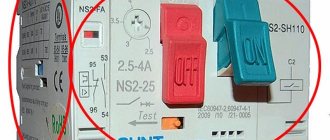
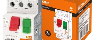
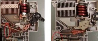
Circuit breakers are devices whose task is to protect an electrical line from damage under the influence of large currents. This can be either short-circuit overcurrents or simply a powerful flow of electrons passing through the cable for quite a long time and causing it to overheat with further melting of the insulation. The circuit breaker in this case prevents negative consequences by cutting off the current supply to the circuit. In the future, when the situation returns to normal, the device can be turned on again manually.
Circuit breaker functions
Protective devices are designed to perform the following main tasks:
- Electrical circuit switching (possibility of disconnecting the protected area in the event of power problems).
- De-energizing the entrusted circuit when short-circuit currents occur in it.
- Protection of the line from overloads when an excessive current passes through the device (this happens when the total power of the devices exceeds the maximum permissible).
In short, AVs simultaneously perform protective and control functions.
Selection mistakes to consider
Finally, let's look at the most common mistakes that are made when choosing a circuit breaker.
Error 1.
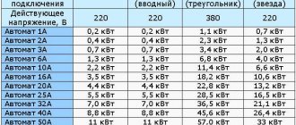
When choosing an automatic machine, they are guided by the total power of consumers, which is one of the most serious mistakes.
The machine only protects the wiring from overloads; it is unable to change its characteristics.
If you place a powerful machine on weak wiring and connect a strong energy consumer to it, this will inevitably lead to damage to the wiring, and the machine will not be able to do its job.
Therefore, you should always focus on the cross-section of the wire and its throughput, and not on the power of the consumers.
Error 2.
Often, all branches of the network are equipped with the same machines, and then they try to use one of the branches as a heavily loaded one.
Even at the stage of installation of the electrical network, it is advisable to ensure that at least one of the branches has increased parameters and is equipped with a circuit breaker designed for significant loads.
For example, in the garage of a private house, it is possible to use devices that create a significant load.
It is better to strengthen this branch in advance than to redo it later or hope that the machine or wiring will “stand.”
Error 3.
When purchasing circuit breakers, buyers try to minimize costs. It's better not to skimp on safety.
You should buy such devices only from well-established companies in specialized stores, and even better from an official distributor.
We hope that the tips above will help you choose the right circuit breaker for your home.
Main types of switches
There are three main types of AVs, differing from each other in design and designed to work with loads of different sizes:
- Modular. It got its name because of its standard width, a multiple of 1.75 cm. It is designed for small currents and is installed in household power supply networks, for a house or apartment. As a rule, this is a single-pole or two-pole circuit breaker.
- Cast. So called because of the cast body. Can withstand up to 1000 Amps and is used primarily in industrial networks.
- Airborne. Designed to work with currents up to 6300 Amperes. Most often this is a three-pole machine, but now devices of this type are also produced with four poles.
A single-phase protective circuit breaker is a circuit breaker that is most common in household networks. It comes in 1- and 2-pole types. In the first case, only the phase conductor is connected to the device, and in the second case, the neutral conductor is also connected.
In addition to the listed types, there are also residual current devices, designated by the abbreviation RCD, and differential circuit breakers.
The former cannot be considered full-fledged AVs; their task is not to protect the circuit and the devices included in it, but to prevent electric shock when a person touches an open area. A differential circuit breaker is an AV and an RCD combined in one device.
Download
For those who are interested in the topic deeper and more thoroughly, I am posting GOST, which describes in detail all the characteristics and terminology regarding circuit breakers.
At the moment, GOST R 50345-99 (IEC 60898-95) (Small electrical equipment. Circuit breakers for protection against overcurrents for household and similar purposes) is not valid, instead GOST R 50345-2010 (IEC 60898-1:2003) has been introduced ( Small-sized electrical equipment. Circuit breakers for overcurrent protection for household and similar purposes. Part 1. Circuit breakers for alternating current). I am posting it for download:
• GOST R 50345-2010 / GOST R 50345-2010 (IEC 60898-1:2003) Small-sized electrical equipment. Automatic switches for overcurrent protection for household and similar purposes. Part 1. Circuit breakers for alternating current. This standard applies to air circuit breakers (hereinafter referred to as circuit breakers) for alternating current for operation at a frequency of 50 or 60 Hz with a rated voltage (between phases) of not more than 440 V, a rated current of not more than 125 A and a rated breaking capacity of not more than 25,000 A. , pdf, 1.89 MB, downloaded: 1057 times./
• Kharechko V.N., Kharechko Yu.V. Automatic switches of modular design / Kharechko V.N., Kharechko Yu.V. Automatic circuit breakers of modular design: Reference manual. The reference manual sets out the requirements of GOST R 50345-99 (IEC 60898-95) for household circuit breakers intended for overcurrent protection, examines the design of circuit breakers, gives characteristics and their classification. Errors are analyzed that are partially corrected in the new version of GOST R 50345-2010, pdf, 7.17 MB, downloaded: 1062 times./
I look forward to questions and criticism in the comments!
How are circuit breakers arranged?
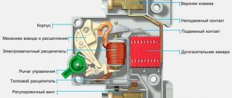
Let us consider in detail the device of the circuit breaker. The body of the machine is made of dielectric material. It consists of two parts, which are connected to each other with rivets. If it is necessary to disassemble the housing part, the rivets are drilled out, and access to the internal elements of the circuit breaker is opened. These include:
- Screw terminals.
- Flexible conductors.
- Control handle.
- Movable and fixed contact.
- An electromagnetic release, which is a solenoid with a core.
- Thermal release, which includes a bimetallic plate and an adjusting screw.
- Gas outlet.
- Arcing chamber.
On the rear side, the automatic protective fuse is equipped with a special lock, with which it is mounted on a DIN rail.
The latter is a metal rail 3.5 cm wide, onto which modular devices, as well as some types of electric meters, are mounted. To attach the machine to the rail, the body of the protective device should be inserted over its upper part, and then snap the latch by pressing on the lower part of the device. You can remove the circuit breaker from the DIN rail by lifting the latch from below.
The modular switch lock may be very tight. To attach such a device to a DIN rail, you need to first pick up the latch from below and place the protective device in place of the fastener, then release the fixing element.
You can make it simpler - when snapping the latch, press firmly on its lower part with a screwdriver.
It is clear why a circuit breaker is needed in the video:
Normal operating mode
In normal mode, a current flows through the circuit breaker that is less than or equal to the rated current.
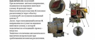
In this case, the supply voltage is supplied to the upper terminal, which is connected to the fixed contact.
From the latter, the current flows to the moving contact, then through a flexible copper conductor to the solenoid.
Next, the current from the solenoid flows to the release (thermal relay) and then to the terminal located below. It is she who connects to electricity consumers.
Operating principle of circuit breaker
Now let's figure out how the network circuit breaker works. It is connected by lifting the control handle upwards. To disconnect the AB from the network, the lever is lowered down.
When the electrical protective circuit breaker operates in normal mode, the electric current when the control handle is raised up is supplied to the device through the power cable connected to the upper terminal. The flow of electrons goes to the fixed contact, and from it to the moving one.
Then, through a flexible conductor, the current flows to the solenoid of the electromagnetic release. From it, electricity goes through a second flexible conductor to a bimetallic plate included in the thermal release. Having passed along the plate, the flow of electrons through the lower terminal goes into the connected network.
Features of the thermal release
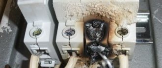
When the current in the circuit in which the circuit breaker is installed exceeds the device rating, an overload occurs. A high-power electron flow, passing through a bimetallic plate, has a thermal effect on it, making it softer and causing it to bend towards the disconnecting element. When the latter comes into contact with the plate, the machine is triggered and the current supply to the circuit is stopped. Thus, thermal protection helps prevent excessive heating of the conductor, which can lead to melting of the insulating layer and failure of the wiring.
Heating the bimetallic plate to such an extent that it bends and triggers the AB occurs over a certain period of time. It depends on how much the current exceeds the rating of the machine, and can take a few seconds or an hour.
The thermal release is triggered if the current in the circuit exceeds the nominal value of the machine by at least 13%. After the bimetallic strip has cooled and the current current has normalized, the protective device can be turned on again.
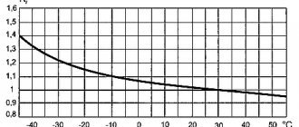
There is another parameter that can affect the operation of the AV under the influence of a thermal release - this is the ambient temperature.
If the air in the room where the device is installed is at a high temperature, the plate will heat up to the tripping limit faster than usual and can trip even with a slight increase in current. Conversely, if the house is cold, the plate will heat up more slowly, and the time before the circuit turns off will increase.
The operation of the thermal release, as mentioned, requires a certain time, during which the circuit current can return to normal. Then the overload will disappear and the device will not shut down. If the magnitude of the electric current does not decrease, the machine de-energizes the circuit, preventing the melting of the insulating layer and preventing the cable from catching fire.
The cause of overload is most often the inclusion in the circuit of devices whose total power exceeds the calculated power for a particular line.
Nuances of electromagnetic protection
An electromagnetic release is designed to protect the network from short circuits and differs in operating principle from a thermal release. Under the influence of short-circuit supercurrents, a powerful magnetic field arises in the solenoid. It moves the coil core to the side, which opens the power contacts of the protective device, acting on the release mechanism. The power supply to the line is stopped, thereby eliminating the risk of fire in the wiring, as well as destruction of the closed installation and circuit breaker.
Since in the event of a short circuit in the circuit there is an instantaneous increase in the current to a value that can lead to serious consequences in a short time, the operation of the circuit breaker under the influence of an electromagnetic release occurs in hundredths of a second. True, in this case the current must exceed the nominal value of the AB by 3 or more times.
Video about circuit breakers:
Arc chamber
When the contacts of a circuit through which electric current flows open, an electric arc appears between them, the power of which is directly proportional to the magnitude of the mains current. It has a destructive effect on the contacts, therefore, to protect them, the device includes an arc-extinguishing chamber, which is a set of plates installed parallel to each other.
Upon contact with the plates, the arc fragments, as a result of which its temperature decreases and attenuation occurs. Gases generated when an arc occurs are removed from the body of the protective device through a special hole.
Overload mode
Overload mode is when the current consumed by the load connected to the machine becomes higher than the rated value of the device. In this case, the current that passes through the release causes heating of the bimetal plate, which leads to an increase in its bending. This causes the release mechanism to operate. At this moment, the machine turns off and the circuit opens.
Thermal protection does not work instantly, since it takes some time for the plate to heat up. And it varies depending on how much the rated current is exceeded. The time period can vary from a couple of seconds to an hour. The delay will allow you to get rid of power outages during a short and random increase in current. Often such excesses can be observed when starting the electric motor.
Acoustic
Such switches are also called clap or sound switches. Turning on occurs by giving a sound signal of a certain volume, for example, clapping your hands. Switches of this type with a timer are installed not only in apartments, but also on staircases. Some models provide a time setting after which the switch disconnects the circuit. Often, acoustic switches are hidden in distribution boxes and are duplicated by regular keyboards.
The main advantage of this model is obvious: with it you don’t have to feel for the switch in the dark or walk across the entire apartment in dirty shoes because you forgot to turn off the lights. However, such devices do not always respond the first time and can operate spontaneously, which sometimes irritates owners.
Rope
The operating principle of this switch is similar to a push-button switch: by pulling the string until it clicks, you close the contacts. Pull a second time and open. This type of switch is primarily used in wall sconces and sometimes for turning on exhaust fans.
Rope switches are not only used for decorative purposes; they have a number of practical advantages. For example, a dangling cord is easy to find by touch in the dark, and such switches are also suitable for families with small children; the child can easily reach it and be able to turn the light on and off independently.
Rotary
About 50 - 60 years ago, rotary switches were still actively used in the construction of houses, but recently they have been used only in “antique” design projects or in creating interiors in country, loft, and Provence styles. As a rule, they are produced only for outdoor installation and are used in conjunction with open wiring. Switched by turning the lever 90°.
Keyboards
The most common type of switches. The electrical circuit is closed and opened when the key is switched from one position to another. One-, two- and three-key versions are available.
Key switches are inexpensive, convenient to use and easy to repair. On the other hand, they have a rather low operating life, the lighting intensity cannot be adjusted, and there is no energy saving mode.
Literature
1. Description and performance characteristics of modular equipment and RAS control devices. Devices for protection, switching, measurement and control. Catalog LV 10.1. 2013 edition
2. Description and characteristics of the equipment. Modular circuit breakers 5SL. BETA modular equipment. Answers for infrastructure and cities. ©Siemens AG 2010.
3. Description and performance characteristics of RCD 5SM3416-8. ©Copyright Siemens AG 2013.
4. ;
5. https://pa.compeljournal.ru/; https://pa.compeljournal.ru/enews.
Obtaining technical information, ordering samples, delivery - e-mail
•••
Push-button
The principle of operation of a push-button switch is similar to a key switch: you press the button - it locks and closes the contact. Pressing it again opens the contact. Often available with LED backlighting. Such switches should not be confused with ordinary electrical buttons, for example, on a bell: such buttons make a contact only if they are held by hand.
Push-button switches will easily fit into the interior of any room, despite their slightly non-standard appearance. They cost a little more than their keyboard counterparts. But they will serve you faithfully for a long time.
Checking the functionality of releases
The functionality check includes the following steps:
Visual inspection of the switch. There should be no mechanical damage on the device body: chips or cracks
Pay attention to the tightness of the parts, the quality of fasteners and clamps. Do a few test manipulations of “turning on and off” manually
In the on position, the device should click into place and then turn off freely. Loading the device. The test consists of determining the response time of the release when power is supplied with an adjustable current strength on a special stand. The obtained result is compared with the typical time-current characteristic of the AB model.
The modern market of electrical equipment offers the consumer a wide range of releases. These devices are equipped with devices of 1-3 phase alternating AC and direct current DC and voltage up to 1000 V.
Remote
These are switches that are activated by a signal from the remote control. There are also combined models: for example, a touch switch with a remote control. Remote switches are not very common because they are quite expensive. In addition, remote controls tend to get lost.
But there are also advantages. Firstly, with remote switches you don’t have to damage the walls: you just need to arm yourself with self-tapping screws or double-sided tape and secure the switches in the right places. And no problems with fixed wiring. Secondly, you can turn light bulbs on and off from anywhere in your apartment or house and feel like the master of light.
Varieties of the model range
Many home craftsmen prefer to use time-tested independent releases. Such units operate solely under the influence of voltage, which gradually passes through the main circuit of the circuit breaker. The great popularity of such installations arose against the background of the fact that each master can control the system remotely, which is not provided for in other categories of releases.
An automated switch helps to timely disconnect from the power supply absolutely all devices and other sources that operate using electricity. This function is especially important in situations where there is a noticeable voltage deviation in the network from the norm specified by the consumer
But it is important to take into account the disadvantages that are associated with the conversion of energy into heat release. The presence of such a factor may result in the switch being disconnected improperly
Modern Z-ASA/230
Manufacturers note the fact that turning off ventilation in the event of a fire through an independent switch of this series occurs extremely quickly. This model comes with high quality moving modules and six pairs of contacts. This device is especially relevant for impulse switches. The unit works great in extreme conditions where there is high humidity. The device is often used by specialists for remote control. The level of current conductivity is equal to 4.5 microns.
Improved modifications for 30A
This type of release for a circuit breaker is manufactured with a special code expander. The final output voltage is equal to 35 V. The smooth operation of the unit is associated with diode rectifiers. All contacts are mounted on movable plates.
Experts have provided for the presence of transceivers with trimming resistors. Many models in this category are connected to electrical panels via high-quality capacitor units. To prevent the negative impact of unscheduled overloads on the network, expansion dinistors are used.
Unit IEK РН47
Experts confidently claim that this release is one of the most popular. The compactness of this model is of great importance. Reliable fixation with the shield is ensured thanks to small capacitor units. In addition, the model has only two rectifiers, and all contacts are movable.
The expander itself is located in the lower compartment of the structure along with the relay. The presence of a transceiver is not provided.
Particular attention should be paid to the operating parameters of the independent release - the output voltage is within 40 V. The maximum network load should not exceed 30 A
In addition, manufacturers have conducted numerous studies that have shown that the minimum trip temperature is within -10˚C. The unit is not at all afraid of exposure to high humidity. All wiring is insulated in a special way for safe operation of the device.
Household SHUNT 250 VAC
This model of independent release is produced on the basis of a diode rectifier, which is located above the relay
Attention should also be paid to the operating parameters of the system, which are 44 ohms. Standard threshold overload is equal to 24 A
A miniature capacitor unit is used to connect the modification.
All conductors are equipped with powerful insulators. The unit is equipped with three pairs of resistors, securely fixed above the rectifier. Manufacturers did not provide for the presence of a stabilizer. This makes this model ideal for low-power drives.
